

Page 1
INSTALLATION GUIDE
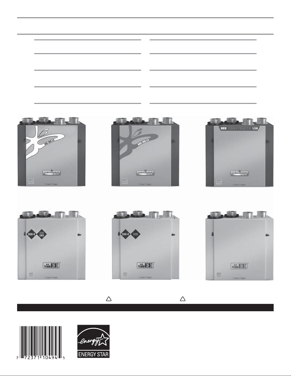
VENMAR AVS
ERV EKO 1.5
HRV EKO 1.5
CONSTRUCTO 1.5V
vänEE
ERV 90H-V ECM
HRV 90H-V ECM
90H-V
THIS UNIT HAS A SPECIAL START-UP
PROCEDURE, REFER TO PA GE 12.
HIS UNIT HAS A SPECIAL START-UP
T
PROCEDURE, REFER TO PA GE 12.
VB0119
THIS UNIT HAS A SPECIAL START-UP
PROCEDURE, REFER TO PA GE 12.
T
HIS UNIT HAS A SPECIAL START-UP
PROCEDURE, REFER TO PA GE 12.
! !
RESIDENTIAL USE ONLY
READ AND SAVE THESE INSTRUCTIONS
These products earned the ENERGY STAR® by
meeting strict energy efficiency guidelines set
by Natural Resources Canada and the US EPA.
They meet ENERGY STAR requirements only
when used in Canada.
08300 rev. 08
Page 2
ABOUT THIS GUIDE
!
Because of the large amount of models covered in this publication, the illustrations are typical ones. Some details of your unit may be
slightly different than the ones shown.
Please take note that this guide uses the following symbols to emphasize particular information:
WARNING
Identifies an instruction which, if not followed, might cause serious personal injuries including possibility of death.
CAUTION
Denotes an instruction which, if not followed, may severely damage the unit and/or its components.
NOTE: Indicates supplementary information needed to fully complete an instruction.
We welcome any suggestions you may have concerning this guidel and/or the unit, and we would appreciate hearing your comments on
ways to better serve you. Please contact us by phone at 1-800-567-3855.
ABOUT THESE UNITS
LIMITATION
For residential (domestic) installation only. Installation work and electrical wiring must be done by a qualified person(s) in accordance with
all applicable codes and standards, including fire-rated construction codes and standards.
WARNING
!
TO REDUCE THE RISK OF FIRE, ELECTRIC SHOCK, OR INJURY TO PERSON(S) OBSERVE THE FOLLOWING:
1. Use this unit only in the manner intended by the manufacturer. If you have questions, contact the manufacturer at the address or
telephone number listed in the warranty.
2. We recommend that your unit be inspected by a specialized technician once a year.
3. Before servicing or cleaning the unit, disconnect power cord from electrical outlet.
4. This unit is not designed to provide combustion and/or dilution air for fuel-burning appliances.
5. When cutting or drilling into wall or ceiling, do not damage electrical wiring and other hidden utilities.
6. Do not use the units with any solid-state speed control device other than the corresponding ones listed below:
UNIT MAIN CONTROL AUXILIARY CONTROL
ERV EKO 1.5, HRV EKO 1.5 ALTITUDE OR DECO-TOUCH 20/40/60-MINUTE PUSH-BUTTON TIMER AND 60-MINUTE CRANK TIMER
ERV 90H-V ECM, HRV 90H-V ECM PLATINUM OR DECO-TOUCH 20/40/60-MINUTE PUSH-BUTTON TIMER AND 60-MINUTE CRANK TIMER
CONSTRUCTO 1.5V
90H-V
7. This unit must be grounded. The power supply cord has a 3-prong grounding plug for your personal safety. It must be plugged into a
mating 3-prong grounding receptacle, grounded in accordance with the national electrical code and local codes and ordinances. Do
not remove the ground prong. Do not use an extension cord.
8. Do not install in a cooking area or connect directly to any appliances.
9. Do not use to exhaust hazardous or explosive materials and vapors.
10. When performing installation, servicing or cleaning these units, it is recommended to wear safety glasses and gloves.
11. Due to the weight of the unit, two installers are recommended to perform installation.
12. When applicable local regulations comprise more restrictive installation and/or certification requirements, the aforementioned
requirements prevail on those of this document and the installer agrees to conform to these at his own expenses.
LITE-TOUCH CONSTRUCTO,
CONSTRUCTO OR DECO-TOUCH
LITE-TOUCH, BRONZE
OR DECO-TOUCH
20-MINUTE LIGHTED PUSH-BUTTON TIMER,
DEHUMIDISTAT AND 60-MINUTE CRANK TIMER
20-MINUTE LIGHTED PUSH-BUTTON TIMER,
DEHUMIDISTAT AND 60-MINUTE CRANK TIMER
CAUTION
1. To avoid prematurate clogged filters, turn OFF the unit during construction or renovation.
2. Please read specification label on product for further information and requirements.
3. Be sure to duct air outside – Do not intake/exhaust air into spaces within walls or ceiling or into attics, crawl spaces, or garage.
4. Intended for residential installation only in accordance with the requirements of NFPA 90B (for a unit installed in USA) or Part 9 of the
National Building Code of Canada (for a unit installed in Canada).
5. Do not run any air ducts directly above or closer than 2 ft (0.61 m) to any furnace or its supply plenum, boiler, or other heat producing
appliance. If a duct has to be connected to the furnace return plenum, it must be connected not closer than 9’ 10” (3 m) from this
plenum connection to the furnace.
6. The ductwork is intended to be installed in compliance with all applicable codes.
7. When leaving the house for a long period of time (more than two weeks), a responsible person should regularly check if the unit
operates adequately.
8. If the ductwork passes through an unconditioned space (e.g.: attic), the ducts must be insulated, and the unit must operate continuously
except when performing maintenance and/or repair. Also, the ambient temperature of the house should never drop below 18°C (65°F).
2
Page 3

TABLE OF CONTENTS
1. TECHNICAL DATA .................................................................................................................................................................4
1.1 AIR DISTRIBUTION ...................................................................................................................................................................... .4
1.2 D
1.3 DIMENSIONS................................................................................................................................................................................ 4
2 TYPICAL INSTALLATIONS ........................................................................................................................................................5
2.1 FULLY DUCTED SYSTEM .............................................................................................................................................................. .5
2.2 CENTRAL DRAW POINT .................................................................................................................................................................5
2.3 SIMPLIFIED INSTALLATION ............................................................................................................................................................... 5
2.4 ATTIC INSTALLATION FOR ERV EKO 1.5 ONLY .................................................................................................................................. 6
3 INSTALLATION ................................................................................................................................................................. 6-11
3.1 INSPECT THE CONTENT OF THE BOX ............................................................................................................................................. .6
3.2 UNIT DOOR(S) ........................................................................................................................................................................... 6
3.3 LOCATING THE UNIT ..................................................................................................................................................................... 6
3.4 PLANNING OF THE DUCTWORK ....................................................................................................................................................... 7
3.5 CALCULATING DUCT SIZE ............................................................................................................................................................. 7
3.6 INSTALLING THE DUCTWORK AND REGISTERS ................................................................................................................................. 8-9
3.7 CONNECTING THE DUCTS TO THE UNIT ......................................................................................................................................... 10
3.8 INSTALLING TWO EXTERIOR HOODS ...............................................................................................................................................11
3.9 CONNECTING THE DRAIN .............................................................................................................................................................11
4. CONTROLS ..................................................................................................................................................................12-15
4.1 UNITS BOOTING SEQUENCE ........................................................................................................................................................ 12
4.2 INTEGRATED CONTROL ................................................................................................................................................................ 12
4.3 SPEED AND DEFROST SETTINGS FOR ERV EKO 1.5, HRV EKO 1.5, ERV 90H-V ECM AND HRV 90H-V ECM UNITS ...................... 13
4.4 SETTING EXTENDED DEFROST FOR CONSTRUCTO 1.5V AND 90H-V UNITS ........................................................................................ 13
4.5 ELECTRICAL CONNECTION TO MAIN CONTROLS ..............................................................................................................................14
4.6 ELECTRICAL CONNECTION TO OPTIONAL AUXILIARY CONTROLS ......................................................................................................... 15
5. ELECTRICAL CONNECTION TO THE FURNACE ........................................................................................................................... 16
6. WIRING DIAGRAMS ....................................................................................................................................................... 17-18
7. B ALANCING THE UNIT .........................................................................................................................................................19
7.1 WHAT YOU NEED TO BALANCE THE UNIT ...................................................................................................................................... 19
7.2 PRELIMINARY STAGES TO BALANCE THE UNIT.................................................................................................................................. 19
7.3 BALANCING PROCEDURE ............................................................................................................................................................. 19
8. SERVICE PARTS ................................................................................................................................................................20
9. TROUBLESHOOTING .......................................................................................................................................................21-22
EFROST CYCLES ........................................................................................................................................................................ 4
3
Page 4

1. TECHNICAL DATA
1.1 AIR DISTRIBUTION
NORMAL OPERATION DEFROST OR RECIRCULATION
STALE AIR
TO OUTSIDE
VF0045
FRESH AIR
FROM OUTSIDE
STALE AIR
FROM
BUILDING
FRESH AIR
BUILDING
TO
VF0046
STALE AIR
FROM
BUILDING
FILTERED AIR
TO
BUILDING
1.2 DEFROST CYCLES
HRV EKO 1.5 AND
HRV 90H-V ECM UNITS
OUTSIDE TEMPERATURE DEFROST CYCLES (MINUTES)EXTENDED DEFROST CYCLES (MIN.) EXTENDED DEFROST CYCLES (MIN.)
°C °F D
EFROSTING
OPERATION BETWEEN
EACH DEFROST CYCLE
DEFROSTING
OPERATION BETWEEN
EACH DEFROST CYCLE
-5 23 7 (HRV) 25 (HRV) 10 20 9 23
-10 14 7 (ERV) 25 (ERV) 10 20 9 23
-27 -17 10 (HRV & ERV) 22 (HRV & ERV) 10 15 10 22
CONSTRUCTO 1.5V
AND 90H-V UNITS
DEFROSTING
OPERATION BETWEEN
EACH DEFROST CYCLE
In a cold region, (outside temperature -27°C [-17°F] and lower), it may be necessary to setup EXTENDED DEFROST.
See Section 4.3 or 4.4, according to the unit model.
1.3 DIMENSIONS
9
/16”
24 9/16”
(624 mm)
(572 mm)
VK0066A
22 ½”
1
/16”
14
(358 mm)
15
14
/16”
(380 mm)
23
(599 mm)
18 ¼”
(464 mm)
4
2 ¹/
16”
(53 mm)
NOTE: Every port fits 6” round duct.
13
3
/16”
(97 mm)
7
/16”
7
(189 mm)
Page 5
2. TYPICAL INSTALLATIONS
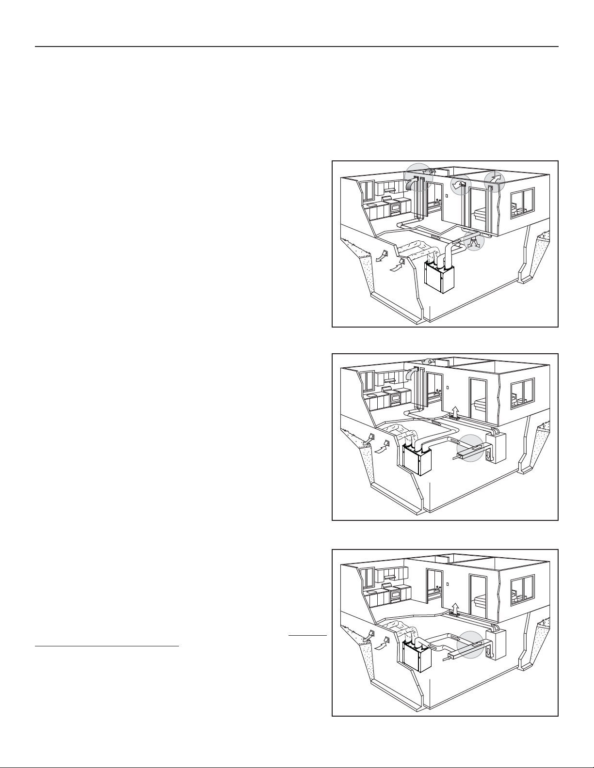
Use the following illustrations as guidelines to help you decide on how the unit will be installed.
All the units should be hung from the joists.
If required, bathroom fans and a range hood may be used to exhaust stale air. Also, for homes with more than one level, we recommend
one exhaust register at the highest level.
There are 3 installation methods: Fully ducted, Central Draw Point and Simplified Installation.
NOTE: An electrical outlet has to be available within 3 feet of the unit.
2.1 FULLY DUCTED SYSTEM (PRIMARILY FOR HOMES WITH RADIANT HOT WATER OR ELECTRIC BASEBOARD HEATING)
Stale air coming from the registers located at the highest level of the house
is exhausted to the outside. Fresh air from outside is filtered and supplied by
the register located in the lowest liveable level.
Homes with more than one level require at least one exhaust register at the
highest level.
See figure at right.
2.2 CENTRAL DRAW POINT (CONNECTION TO A FORCED AIR SYSTEM)
Stale air coming from the registers located at the highest level of the house is
exhausted to the outside. Fresh air from outside is filtered and supplied to the
return (plenum) or the supply duct of the forced air unit. See figure at right.
For this type of installation, it is not essential that the forced air system blower
runs when the unit is in operation, but we recommend it.
NOTE: Home with multiple forced air systems should have one unit on each
system.
2.3 SIMPLIFIED INSTALLATION (CONNECTION TO A FORCED AIR SYSTEM)
Stale air is exhausted to the outside. Fresh air from outside is filtered and
supplied to the return (plenum) or the supply duct of the forced air unit.
See figure at right.
To avoid cross-contamination and achieve the highest efficiencies, the forced
air system blower must always be ON.
NOTE: Home with multiple forced air systems should have one unit on each
system.
VH0071
VH0072
VH0073
5
Page 6
2. TYPICAL INSTALLATIONS (CONT’D)
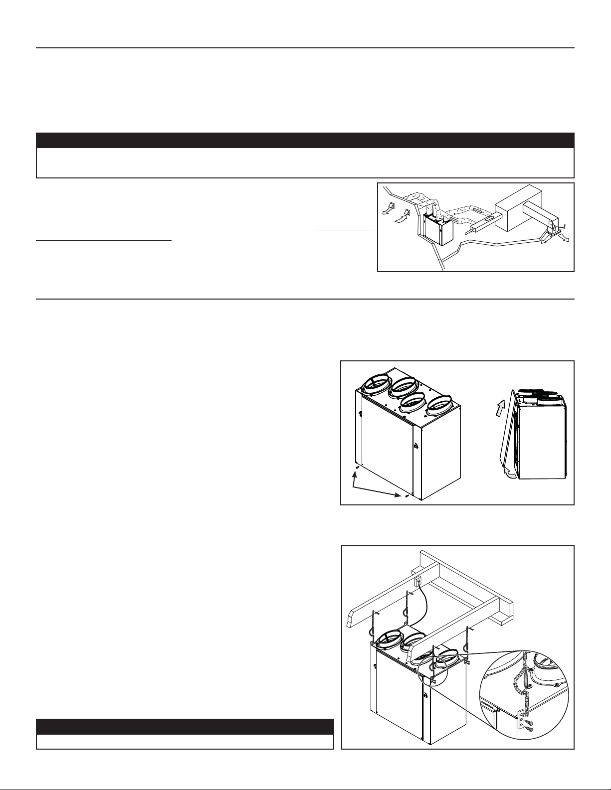
2.4 ATTIC INSTALLATION FOR ERV EKO 1.5 ONLY
All three types of installation can be used in the attic (Fully ducted, Central Draw Point or Simplified). The example shown below is a
Simplified Installation (connection to a forced air system).
NOTE: To get the most of your ERV unit, the ambient temperature around the unit should be conditioned. If the unit has to be installed
in a unconditioned space, the heat gains or losses from the unit and the ducts could increase the operation costs of the unit.
CAUTION
• Due to the potential temperature difference between the attic and the rest of the house, all unit ducts must be insulated.
• The attic temperature must always be above 10°C (50°F) and under 50°C (122°F).
Stale air is exhausted to the outside. Fresh air from outside is filtered and supplied to
the return (plenum) of the forced air unit. See figure at right.
To avoid cross-contamination and achieve the highest efficiencies, the forced air
system blower must always be ON.
NOTE: Home with multiple forced air systems should have one unit on each system.
VH0076
3. INSTALLATION
3.1 INSPECT THE CONTENT OF THE BOX
Inspect the exterior of the unit for shipping damage. Ensure that there is no damage to the door, ports, power cord, etc.
3.2 UNIT DOOR(S)
The ERV EKO 1.5, HRV EKO 1.5, ERV 90H-V ECM and the HRV 90H-V
ECM units have one front door and one back door while the Constructo 1.5V
and the 90H-V units only have one door. For these last models, the unit door
can be relocated on the back of the unit. This can be helpful to optimize duct
configuration while keeping access for unit maintenance. To change door
location, follow these steps:
A. Remove both door lower mechanical screws no. 8-32 x 1” (1) and set
aside.
B. Open (2) and lift out the door (3).
To remove unit back panel, repeat steps A and B, but instead of removing
2 mechanical screws, there are 4 metal screws to be removed. Hang the door
to the back of the unit and secure it by tightening its both lower mechanical
screws. Hang back panel to the front of the unit and secure it by tightening
its four metal screws.
3.3 LOCATING THE UNIT
Choose an appropriate location for the unit.
• Within an area of the house where the ambient temperature is kept
between 10°C (50°F) and 40°C (104°F).
• Away from living areas (dining room, living room, bedroom), if possible.
• So as to provide easy access to the interior of the unit, for semi-annual
and annual maintenance.
• Close to an exterior wall, so as to limit the length of the insulated flexible
duct to and from the unit.
• Away from hot chimneys and other fire hazards.
• Allow for a power source (standard 3-prong grounding outlet).
• Close to a drain. If no drain is close by, use a pail to collect run-off.
Hang the unit with the four chains and springs provided.
See illustration at right.
AB
3
1
VO0149
2
Make sure the unit is level.
CAUTION
VD0205
6
Page 7
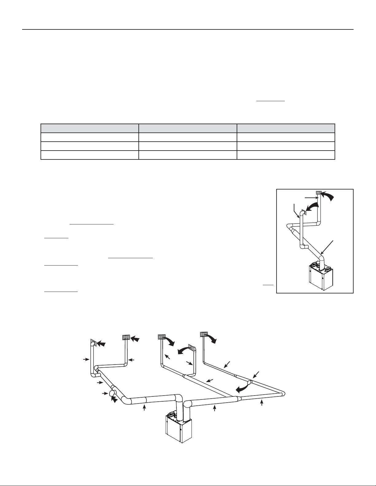
3. INSTALLATION (CONT’D)
3.4 PLANNING OF THE DUCTWORK
• Keep it simple. Plan for a minimum of bends and joints.
• Keep the length of insulated ducts to a minimum.
• Do not ventilate crawl spaces or cold rooms. Do not attempt to recover the exhaust air from a dryer or a range hood. This would cause
clogging of the filters and recovery module.
• If the house has two floors or more, be sure to plan for at least one exhaust register on the highest lived-in level.
3.5 CALCULATING DUCT SIZE
Use the table below to ensure that the ducts you intend to install will be carrying air flows at or under the recommended values.
Avoid installing ducts that will have to carry air flows near the maximum values and never install a duct if its air flow exceeds
the maximum value.
DUCT DIAMETER RECOMMENDED AIR FLOW MAXIMUM AIR FLOW
4” Ø (102 MM) 40 CFM (19 L/S OR 68 M³/H) 60 CFM (28 L/S OR 102 M³/H)
5” Ø (127
6” Ø (152
NOTE: Examples 3.5.1 and 3.5.2 use imperial units. The same calculation applies to metric units.
3.5.1 EXAMPLE OF CALCULATION
Problem: My installation requires two exhaust registers (one for the kitchen, and the other for
the bathroom). I will connect these registers to a main duct which will connect to the unit (high
speed performance value of 140 cfm). What size of duct should I use for the main exhaust duct
and for both end branches leading to the registers? (See illustration at right.)
Solution: Simplified method. (For a more detailed method of calculating duct size, refer to the
ASHRAE or HRAI HANDBOOK.)
Main duct: Table indicates for a 6” Ø duct: recommended air flow: 120 cfm, maximum air flow:
180 cfm. The 140 cfm high speed air flow is close enough to the recommended value (120)
and far away enough from the maximum value (180). Therefore, a 6” Ø duct or larger is an
appropriate choice for the main exhaust duct.
End branches: Each end branch will have to transport a 70 cfm air flow (140 divided by 2). Table
indicates for a 5” Ø duct: recommended air flow: 75 cfm; maximum air flow: 110 cfm. The high
speed air flow of 70 cfm is close enough to the recommended value (75) and far away enough
from the maximum value (110). Therefore, a 5” Ø duct or larger is an appropriate choice for both
end branches.
NOTE: A 4” Ø duct would have been too small because the maximum acceptable value for a 4” Ø duct is 60 cfm.
MM) 75 CFM (35 L/S OR 127 M³/H)110 CFM (52 L/S OR 187 M³/H)
MM) 120 CFM (57 L/S OR 204 M³/H) 180 CFM (85 L/S OR 306 M³/H)
END
BRANCHES
5" Ø,
70 CFM
MAIN BRANCH
6" Ø, 140 CFM
VI0016
3.5.2 Example of a design for a fully ducted system with a unit having a high speed performance of 160 cfm.
4" Ø, 47 CFM
5" Ø, 93 CFM
5" Ø, 67 CFM
4"
VI0017
4" 4"
4" Ø,
CFM
46
5"
6"
6" Ø, 160
4"
CFM
4" Ø,
37
4"
CFM
5"
4"
4" Ø, 24 CFM
5" Ø,
74 CFM
6"
6" Ø, 160 CFM
4"
5" Ø, 62 CFM
5"
5"
5" Ø, 86 CFM
7
Page 8
3. INSTALLATION (CONT’D)
!
!
3.6 INSTALLING THE DUCTWORK AND REGISTERS
3.6.1 FULLY DUCTED SYSTEM (AS ILLUSTRATED IN SECTION 2.1)
WARNING
Never install a stale air exhaust register in a closed room where a combustion device operates, such as a gas
furnace, a gas water heater or a fireplace.
Stale air exhaust ductwork
• Install the stale air exhaust registers where the contaminants are produced: kitchen, living room, etc. Position the registers as far
from the stairway as possible and in such a way that the air circulates in all the lived-in spaces in the house.
• If a register is installed in the kitchen, it must be located at least 4 feet (1.2 m) from the range.
• Install the registers 6 to 12 inches (152 to 305 mm) from the ceiling on an interior wall OR install them in the ceiling.
• If possible, measure the velocity of the air flowing through the registers. If the velocity is higher than 400 ft/min (122 m/min), then
the register type is too small. Replace with a larger one.
Fresh air distribution ductwork
• Install the fresh air distribution registers in bedrooms, dining rooms, living room and basement.
• Keep in mind that the fresh air registers must be located as far as possible from the stale air registers.
• Install the registers either in the ceiling or high on the walls with air flow directed towards the ceiling. (The cooler air will then cross
the upper part of the room and mix with room air, before descending to occupant’s level.)
• If a register must be floor installed, direct the airflow up the wall.
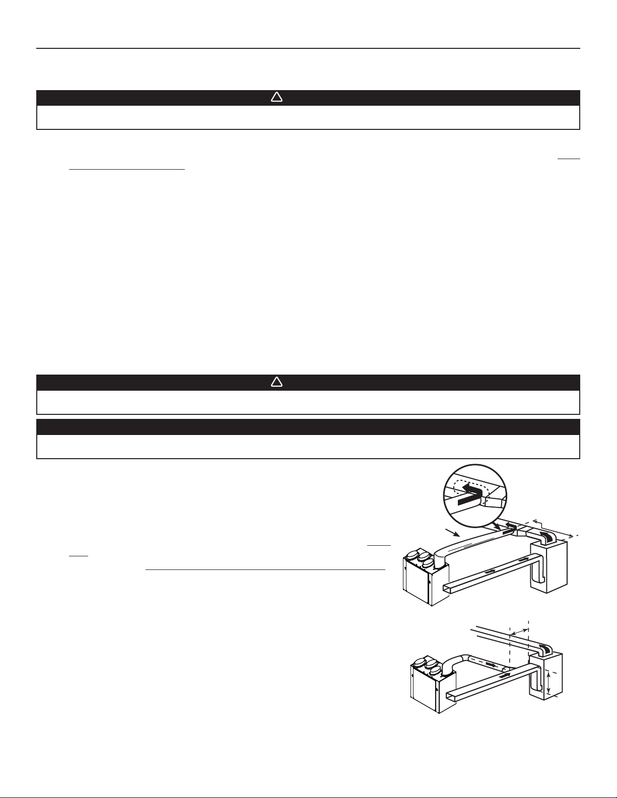
3.6.2 CENTRAL DRAW POINT SYSTEM (AS ILLUSTRATED IN SECTION 2.2)
Stale air exhaust ductwork
Same as for Fully Ducted System, described on point 3.6.1
WARNING
When performing duct connections, always use approved tools and materials. Respect all corresponding laws and
safety regulations. Please refer to your local building code.
CAUTION
When performing duct connections to the furnace supply duct, this duct must be sized to support the additional
airflow produced by the unit. Also, the use of metal duct is highly recommended.
Fresh air distribution ductwork
• There are 2 methods for connecting the unit to the furnace/air handler:
Method 1: Supply side connection
• Cut an opening into the furnace supply duct at least 18 inches (0.5 m) from the
furnace/air handler.
• Connect this opening to the Fresh air distribution port of the unit (use metal
duct, see figure at right).
• Make sure the unit duct forms an elbow inside the furnace/air handler ductwork.
• If desired, interlock (synchronize) the furnace/air handler blower operation (see
Section 5 ELECTRICAL CONNECTION TO FURNACE).
Method 2: Return side connection
• Cut an opening into the furnace return duct not less than 10 feet (3.1 m) from the
furnace/air handler (A+B).
• Connect this opening to the Fresh air distribution port of the unit (see figure at
right).
NOTE: For Method 2, it is not essential that the furnace/air handler runs when the
unit is operation, but we recommend it. If desired, interlock (synchronize)
the furnace/air handler blower operation (see Section 5 ELECTRICAL
CONNECTION TO FURNACE).
METAL DUCT
VJ0061
VJ0062
A+B = NOT LESS
THAN 10’ (3.1 M)
MINIMUM 18"
(0.5 M)
A
B
8
Page 9
3. INSTALLATION (CONT’D)
!
3.6 INSTALLING THE DUCTWORK AND REGISTERS (CONT’D)
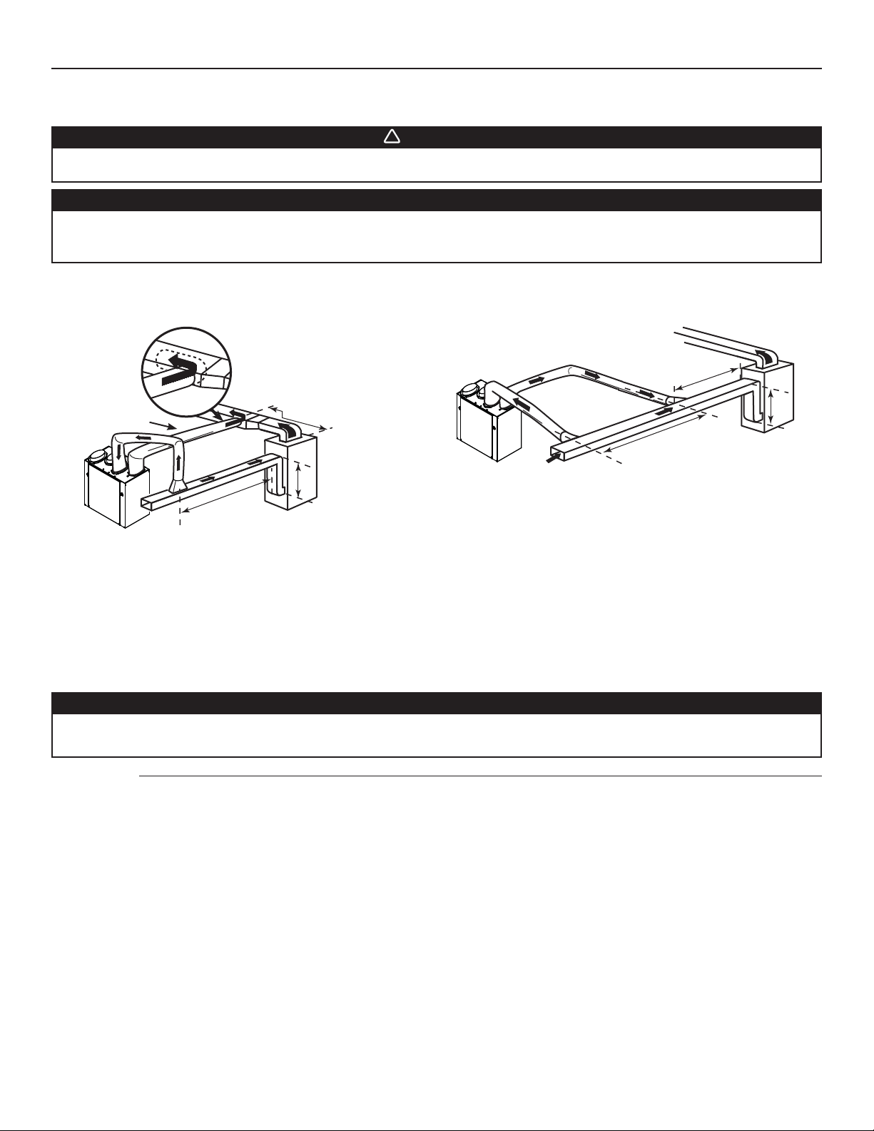
3.6.3 SIMPLIFIED INSTALLATION (AS ILLUSTRATED IN SECTION 2.3)
WARNING
When performing duct connections, always use approved tools and materials. Respect all corresponding laws and
safety regulations. Please refer to your local building code.
CAUTION
When performing duct connections to the furnace supply duct (Method 1), this duct must be sized to support the
additional airflow produced by the unit. Also, the use of metal duct is highly recommended. For a Return-Return
installation, the furnace blower must be in operation when the unit is in operation.
There are 2 methods for connecting the unit to the furnace/air handler:
Method 1: Supply-return connection Method 2: Return-return
A
METAL DUCT
MINIMUM 18"
(0.5 M)
VJ0064
MINIMUM 3'
(0.9 M)
A+B = NOT LESS
THAN 10’ (3.1 M)
B
B
A
VJ0063
A+B = NOT LESS
THAN 10’ (3.1 M)
Stale air intake
• Cut an opening into the furnace/air handler return duct not less than 10 feet (3.1 m) from the furnace/air handler (A+B).
• Connect this opening to the Exhaust air from building port of the unit.
Fresh air distribution
• Same instructions as for Method 1 or Method 2, Section 3.6.2.
For Method 2 (Return-return), make sure there is a distance of at least 3 feet (0.9 m) between the 2 connections to the furnace/
air handler.
CAUTION
If using Method 2, make sure the furnace/air handler blower operation is synchronized with the unit operation!
See Section 5.
NOTE: For Method 1, it is not essential to synchronize the furnace blower operation with the unit operation, but we recommend it.
9
Page 10
3. INSTALLATION (CONT’D)
3.7 CONNECTING THE DUCTS TO THE UNIT
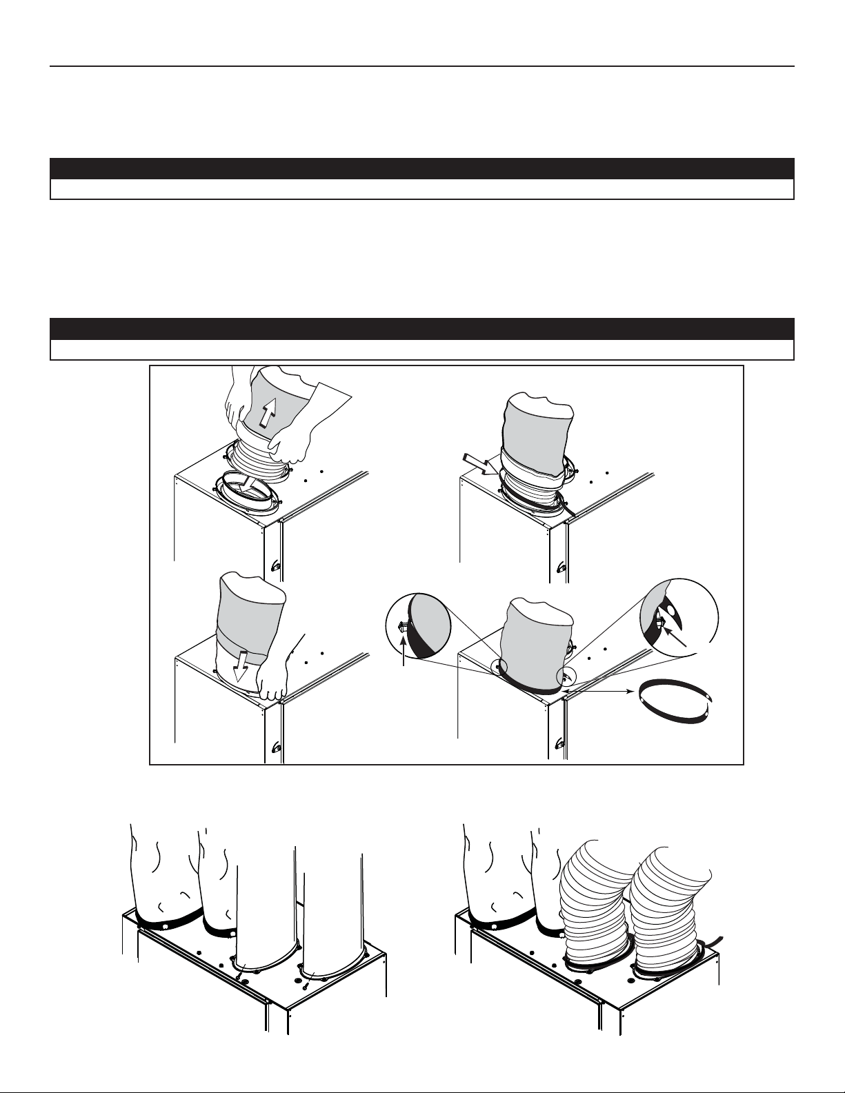
Insulated flexible ducts
Use the following procedure to connect the insulated flexible ducts to the ports of the unit (Exhaust air to outside and Fresh air from
outside ports).
CAUTION
If ducts have to go through an unconditioned space (e.g.: attic), always use insulated ducts.
1. Pull back the insulation to expose the flexible duct.
2. Attach the flexible duct to the port using tie wrap.
3. Pull the insulation over the joint and tuck in between the inner and outer rings of the double collar.
4. Pull down the vapor barrier (shaded part in illustrations below) over the outer ring to cover it completely. Fasten in place the vapor
barrier using the port strap (included in unit parts bag). To do so, insert one collar pin through vapor barrier and first strap hole,
then insert the other collar pin through vapor barrier and center strap hole and close the loop by inserting the first collar pin in the
last strap hole.
CAUTION
Make sure the vapor barrier on the insulated ducts does not tear during installation to avoid condensation within the ducts.
COLLAR PIN
VJ0067
Non-insulated rigid ducts
Use metal screws and duct tape to connect the rigid ducts to the
unit ports.
VJ0066
COLLAR PIN
Non-insulated flexible ducts
Use tie wraps to connect the flexible ducts to the unit ports.
10
Page 11
3. INSTALLATION (CONT’D)
!
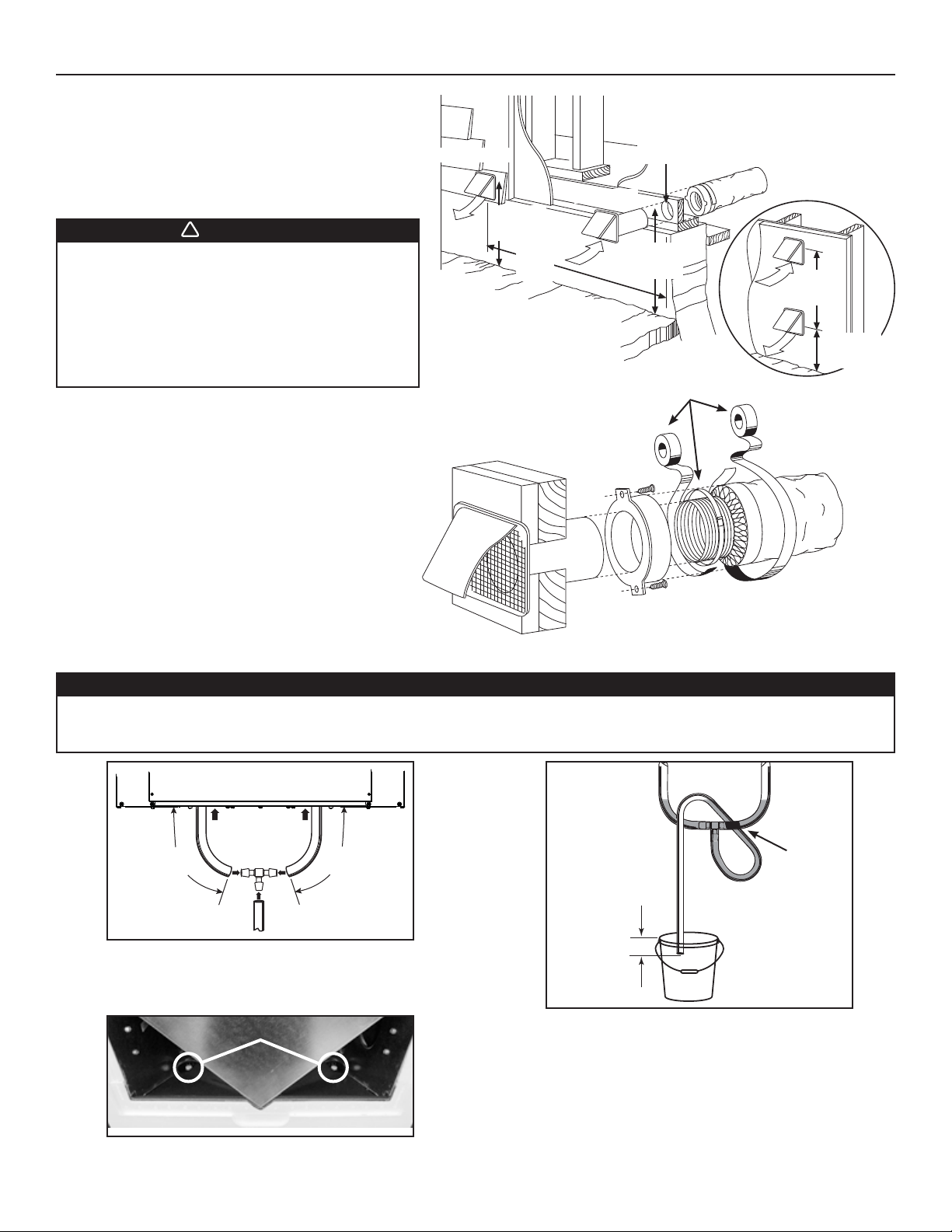
3.8 INSTALLING TWO EXTERIOR HOODS
Choose an appropriate location to install the exterior hoods:
• There must be a minimum distance of 6 feet (1.8 m)
between the hoods to avoid cross-contamination
• There must be a minimum distance of 18 inches
(457 mm) from the ground
WARNING
Make sure the intake hood is at least 6 feet (1.8 m)
away from any of the following:
• Dryer exhaust, high efficiency furnace vent,
central vacuum vent
• Gas meter exhaust, gas barbecue-grill
• Any exhaust from a combustion source
• Garbage bin and any other source of contamination
Refer to figure at right for connecting insulated ducts to the
exterior hoods. An “Anti-gust intake hood’’ should be installed
in regions where a lot of snow is expected to fall.
EXHAUST HOOD
(457 MM)
18"
(1.8 M)
6'
INTAKE HOOD
6" Ø
(152 MM)
18"
(457 MM)
TAPE AND DUCT TIE
PTIONAL DUCT
O
LOCATION
6'
(1.8 M)
18"
(457
MM)
VD0028
3.9 CONNECTING THE DRAIN
CAUTION
A drain tubing (included) must be installed for all HRV units. For ERV units, it is not required, however, it is
recommended for climates where the outside temperature typically remains below -25°C (-13°F), (over a 24-hour
period) for several days in a row, combined with an indoor humidity of 40% or higher.
16"
(406 mm)
VO0176A
Cut 2 sections of the plastic tube, at least 16” (406 mm) long, and
attach them to each inner drain fitting, located under the unit.
Join both short sections to the “T” junction and main tube as shown.
DRAIN PLUGS
VD0239
NOTE: For ERV units, remove both drain plugs inside the unit prior
to install tubing.
16"
(406 mm)
TIE WRAP
± 1”
VD0232A
Make a water trap loop in the tube to prevent the unit from
drawing unpleasant odors from the drain source. Make sure this
loop is located OVER the “T” as shown. Run the tube to the floor
drain or to an alternative drain pipe or pail.
IMPORTANT
If using a pail to collect water, locate the tube end approximately
1” from the top of the pail in order to prevent water from being
drawn back up into the unit.
11
Page 12
4. CONTROLS
All units are equipped with an integrated control located under the unit, on the recessed side of electrical compartment. Plug the unit.
4.1 UNITS BOOTING SEQUENCE
The unit booting sequence is similar to a personnal computer boot sequence. Each time the unit is plugged after being unplugged, or after
a power failure, the unit will perform a 30-second booting sequence before starting to operate.
4.1.1 ERV EKO 1.5, HRV EKO 1.5, ERV 90H-V ECM and HRV 90H-V ECM
During the booting sequence, the integrated control LED will light AMBER for 10 seconds. After that, the LED will light RED
for the rest of the booting sequence. During this RED light phase, the unit is checking and resetting the motorized damper
position. Once the motorized damper position completely set, the RED light turns off and the booting sequence is done.
NOTE: No command will be taken until the unit is fully booted.
4.1.2 C
During the booting sequence, the integrated control LED will light GREEN (unit set in normal defrost) or amber (unit set in
NOTE: No command will be taken until the unit is fully booted.
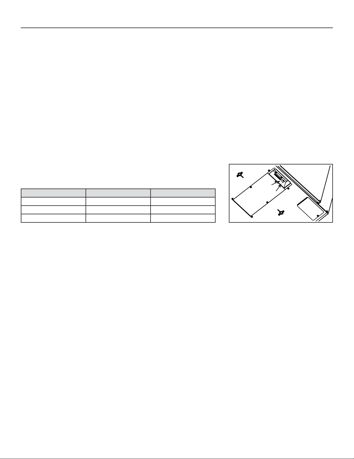
4.2 INTEGRATED CONTROL
Use the push button (1) to control the unit. The LED (2) will then show on which mode the
unit is in.
ONSTRUCTO 1.5V AND 90H-V
extended defrost) for 5 seconds, and then will shut off for 2 seconds. After that, the LED will light RED for the rest of the booting
sequence. During this RED light phase, the unit is checking and resetting the motorized damper position. Once the motorized
damper position completely set, the RED light turns off and the booting sequence is done.
Refer to table below to see how to operate the unit using its integrated control.
PRESS ON PUSH BUTTON LED COLOR RESULTS
2
1
ONCE AMBER UNIT IS ON LOW SPEED
TWICE GREEN UNIT IS ON HIGH SPEED
THREE TIMES NO LIGHT UNIT IS OFF
VD0206
BOTTOM OF THE UNIT
If a problem occurs during the unit operation, its integrated control LED (2) will blink. The color of the blinking light depends on the type
of error detected. Refer to Section 9 Troubleshooting on page 21 for further details.
NOTE: When using main control, the integrated control must be turned off.
12
Page 13
4. CONTROLS (CONT’D)
4.3 SPEED AND DEFROST SETTINGS FOR ERV EKO 1.5, HRV EKO 1.5, ERV 90H-V ECM AND HRV 90H-V ECM UNITS
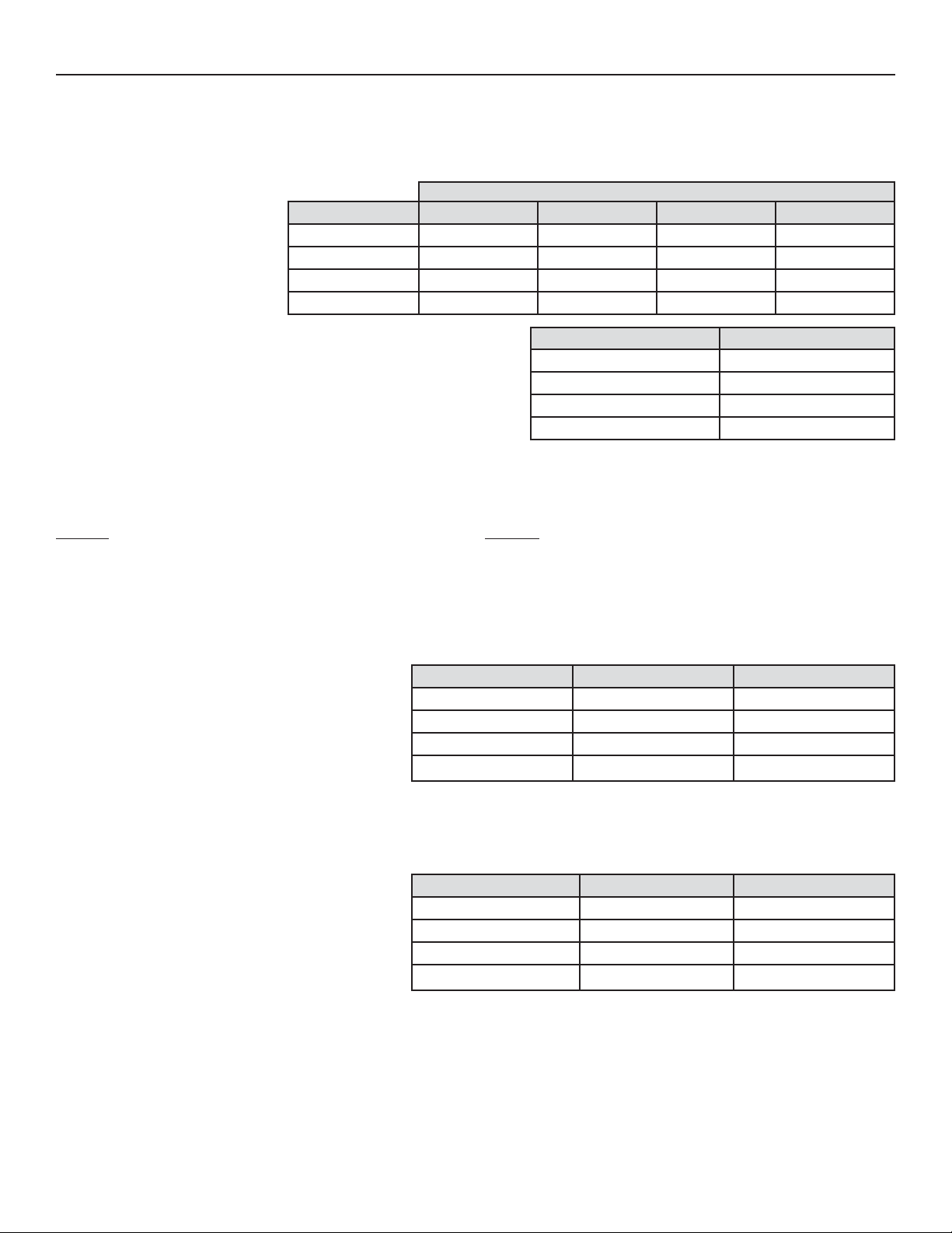
The special design of ERV EKO 1.5, HRV EKO 1.5, ERV 90H-V ECM and HRV 90H-V ECM units offers 4 speed ranges to better meet to
different ventilation needs.
Refer to the table below to choose the right speed range according to the size of the house:
CFM VALUES
NOTE: These CFM values are
approximate, they may vary
according to the installation
static pressure.
These units are factory set to normal defrost. In cold region (outside
temperature -27°C [-17°F] and lower), it may be necessary to setup extended
defrost.
TO MODIFY THE FACTORY SETTINGS, PROCEED AS FOLLOW:
NOTE: Anytime in setting process, if there is no activation on push button for 60 seconds, the unit will automatically exit setting mode, but
the settings made before this 60-second delay will remain.
ACTION
During the first 7 seconds of booting sequence, while the
integrated control LED is AMBER, press on push button for about
3 seconds.
Set the speed range by presssing consecutively on push button
the number of times corresponding to the desired speed range.
See table below.
NOTE: It is possible to change the selection as many
times needed.
SPEED RANGE HRV MIN. SPEED HRV MAX. SPEED ERV MIN. SPEED ERV MAX. SPEED
1 HIGH (FACTORY SET) 80 CFM 157 CFM 84 CFM 140 CFM
2 MED-HIGH 66 CFM 132 CFM 67 CFM 120 CFM
MED-LOW 53 CFM 106 CFM 53 CFM 105 CFM
3
LOW 40 CFM 80 CFM 40 CFM 80 CFM
4
DEFROST TABLE DEFROST CYCLE
1 FACTORY SET (HRV UNITS) NORMAL (HRV UNITS)
2E
ACTORY SET (HRV UNITS) NORMAL (ERV UNITS)
3 F
4E
XTENDED (HRV UNITS)
XTENDED (ERV UNITS)
RESULT
The LED will blink RED one time every 3 seconds to indicate the
integrated control is in CFM setup mode (HIGH speed).
Every 3 seconds, the LED will blink RED the number of times
corresponding to the chosen speed range.
See table below.
SPEED RANGE PRESS ON PUSH BUTTON LED BLINKS RED
HIGH ONCE 1 TIME
1
2 MED-HIGH TWICE 2 TIMES
3 MED-LOW THREE TIMES 3 TIMES
4 LOW FOUR TIMES 4 TIMES
Press on push button for about 3 seconds to access setting
defrost mode.
Press on push button twice to set the unit in extended defrost
mode.
The LED will blink GREEN one time every 3 seconds to indicate
the unit is set in normal defrost mode.
The LED will blink GREEN twice every 3 seconds to indicate the
unit is in extended defrost mode.
DEFROST TABLE PRESS ON PUSH BUTTON LED BLINKS GREEN
NORMAL (HRV UNITS)ONCE 1 TIME
1
NOTE: It is possible to change the selection as many
times needed.
2 EXTENDED (HRV UNITS)TWICE 2 TIMES
3 NORMAL (ERV UNITS)THREE TIMES 3 TIMES
4 EXTENDED (ERV UNITS)FOUR TIMES 4 TIMES
Wait 60 seconds OR press 3 seconds on push button to exit
setting mode.
The LED will blink and shut off, then light RED (the unit returns
in its booting sequence).
4.4 SETTING EXTENDED DEFROST FOR CONSTRUCTO 1.5V AND 90H-V UNITS
These units are factory set to normal defrost. In cold region (outside temperature -27°C [-17°F] and lower), it may be necessary to setup
extended defrost. During the first 2 seconds of booting sequence, while the integrated control LED is GREEN, press on push button for
3 seconds to set the unit in extended defrost; the LED will blink AMBER to show the unit is in extended defrost mode. After that, the LED
will shut off, then light RED (the unit returns in its booting sequence).
13
Page 14
4. CONTROLS (CONT’D)
!
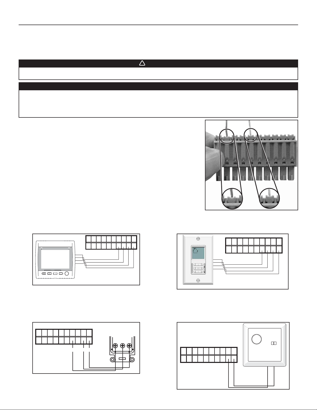
4.5 ELECTRICAL CONNECTION TO MAIN CONTROLS
For more convenience, these units can also be controlled using an optional main wall control.
NOTES: 1. The integrated control must be turned OFF to use an optional main control.
2. If an optional auxiliary control is used, if activated, this auxiliary control will override the optional main control.
WARNING
Always disconnect the unit before making any connections. Failure in disconnecting power could result in electrical
shock or damage of the wall control or electronic module inside the unit.
CAUTION
Never install more than one optional main wall control per unit. Make sure that the wires do not short-circuit
between themselves or by touching any other components on the wall control. Avoid poor wiring connections. To
reduce electrical interference (noise) potential, do not run wall control wiring next to control contactors or near
light dimming circuits, electrical motors, dwelling/building power or lighting wiring, or power distribution panel.
Use the terminal connector included in the installation kit to perform the electrical
connection for main and optional wall controls. Check if all wires are correctly inserted in
their corresponding holes in the terminal block. (A wire is correctly inserted when its orange
receptacle is lower than another one without wire. On picture at right, wire A is correctly
inserted, but wire B is not.)
4.5.1 E
LECTRICAL CONNECTION TO ALTITUDE (ERV EKO 1.5 AND
HRV EKO 1.5 UNITS ONLY) OR PLATINUM (ERV 90H-V ECM
AND HRV 90H-V ECM UNITS ONLY) MAIN WALL CONTROL
NO C NC I OC OL Y R G B
VE0181
MODE
PREF
SET
SMART
4.5.3 ELECTRICAL CONNECTION TO LITE-TOUCH CONSTRUCTO
(CONSTRUCTO 1.5V UNIT ONLY) OR LITE-TOUCH BRONZE
(90H-V UNIT ONLY) MAIN WALL CONTROL
MAIN WALL CONTROL
LITE-TOUCH CONSTRUCTO
or
NO C NC I OC OL Y R G B
LITE-TOUCH BRONZE
REAR VIEW
AB
VE0106
4.5.2 ELECTRICAL CONNECTION TO DECO-TOUCH MAIN WALL CONTROL
(ALL UNITS*)
NO C NC I OC OL Y R G B
VE0250
* Recirculation mode not available for 90H-V and Constructo 1.5V units.
4.5.4 ELECTRICAL CONNECTION TO CONSTRUCTO
(CONSTRUCTO 1.5V UNIT ONLY) OR BRONZE
(90H-V UNIT ONLY) MAIN WALL CONTROL
B G
OC
NO C NC I OC OL Y R G B
VE0187
VE0186A
G
Y
B
14
Page 15
4. CONTROLS (CONT’D)
4.6 ELECTRICAL CONNECTION TO OPTIONAL AUXILIARY CONTROLS
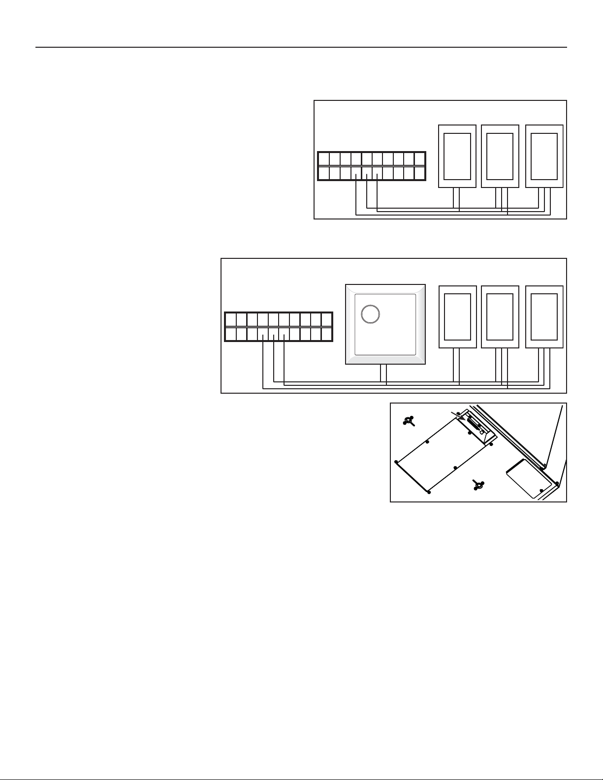
4.6.1 ELECTRICAL CONNECTION TO 20/40/60-MINUTE PUSH BUTTON TIMER OR 60-MINUTE CRANK TIMER
(ERV EKO 1.5, HRV EKO 1.5, ERV 90H-V ECM AND HRV 90H-V ECM UNITS ONLY)
20/40/60-MINUTE
60-MINUTE
CRANK TIMER
NO C NC I OC OL Y R G B
VE0188A
4.6.2 ELECTRICAL CONNECTION TO DEHUMIDISTAT OR 20-MINUTE LIGHTED PUSH BUTTON TIMER OR 60-MINUTE CRANK TIMER (CONSTRUCTO 1.5V AND
90H-V UNITS ONLY)
PUSH-BUTTON SWITCHES
(5 MAXIMUM)
DEHUMIDISTAT
NOTE: If an optional auxiliary control is
activated and then, the Dehumidistat
is being activated, the Dehumidistat
NO C NC I OC OL Y R G B
will override the auxiliary control
commands.
VE0267A
Once the control(s) connections have been made, insert the terminal connector on the
recessed side of electrical compartment.
NOTE: For information about the operation of the wall controls, refer to the user guide.
VD0206
60-MINUTE
CRANK TIMER
TERMINAL
CONNECTOR
BOTTOM OF THE UNIT
20-MINUTE
PUSH-BUTTON SWITCHES
(5 MAXIMUM)
15
Page 16
5. ELECTRICAL CONNECTION TO THE FURNACE
!
WARNING
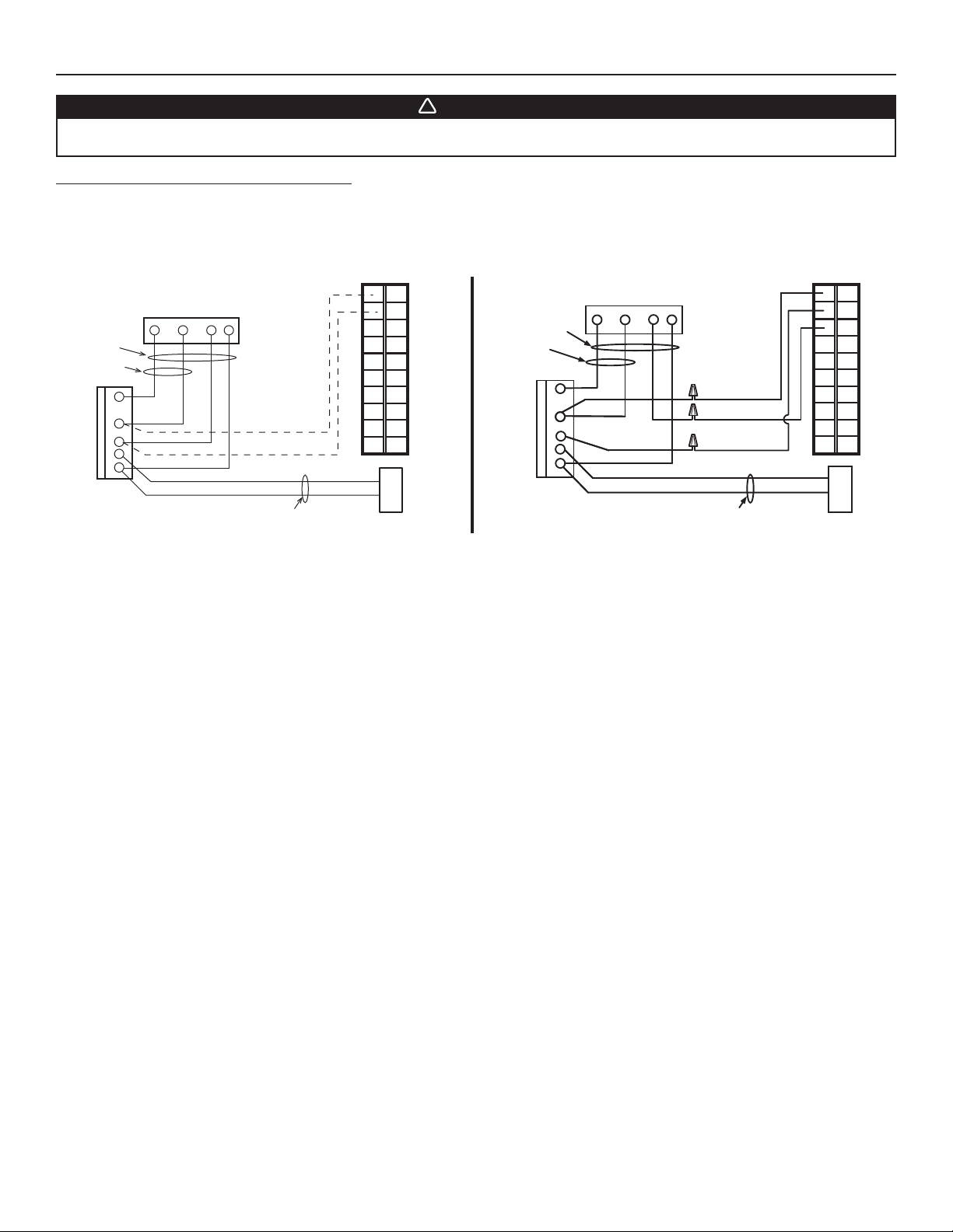
Never connect a 120-volt AC circuit to the terminals of the furnace interlock (standard wiring). Only use the low
voltage class 2 circuit of the furnace blower control.
For a furnace connected to a cooling system:
On some older thermostats, energizing the “R” and “G” terminals at the furnace has the effect of energizing “Y” at the thermostat and
thereby turning on the cooling system. If you identify this type of thermostat, you must use the
STANDARD FURNACE INTERLOCK WIRING ALTERNATE FURNACE INTERLOCK WIRING
NO C NC I OC OL Y R G B
ALTERNATE FURNACE INTERLOCK WIRING.
NO C NC I OC OL Y R G B
FOUR
WIRES
TWO WIRES
heating only
W
R
G
C
Y
FURNACE
24-VOLT
TERMINAL BLOCK
VE0108A
W R G
THERMOSTAT
Y
TERMINALS
TWO WIRES
COOLING SYSTEM
UNIT TERMINAL CONNECTOR
4 WIRES
2 WIRES
heating only
W
R
G
C
FURNACE
24-VOLT
TERMINAL BLOCK
W R G Y
R
Y
Y
THERMOSTAT
TERMINAL
wiring
nuts
NO
NC
C
2 WIRES
UNIT TERMINAL CONNECTOR
COOLING SYSTEM
16
Page 17
6. WIRING DIAGRAMS
r
!
WARNING
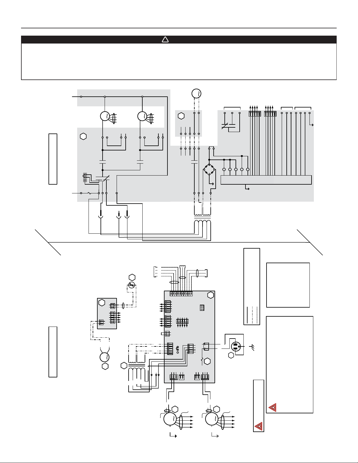
• Risk of electric shocks. Before performing any maintenance or servicing, always disconnect the unit from its power source.
• This product is equipped with an overload protection (fuse). A blown fuse indicates an overload or a short-circuit situation.
If the fuse blows, unplug the product and check the polarity and voltage output from the outlet. Replace the fuse as per the
servicing instructions (refer to wiring diagram for proper fuse rating) and verify the product. If the replaced fuse blows, it may
be a short-circuit and the product must be discarded or returned to an authorized service center for examination and/or repair.
From
supply motor
From
Neutral
J10-1J10-2
120V, 60Hz
A1
JU1
LOGIC DIAGRAM
321
HI MED
Line
120 V, 60Hz
B
Exhaust
K2
F1
J5-2
fan motor
J5-1
J5-3
K1
J9-2
J9-1
J9-3
to A1-J17
J7-2
J9-4
nc
J7-1
R
Supply
fan motor
K3
J4-1
J4-2
J4-3
to A1-J15
J6-2
J6-1
A2
J2-5
J12-5
J2-4
J12-4
J2-3
J12-3
Damper motor
J3-2
J3-1
J2-2
J2-1
J12-2
J12-1
K4
J8-1
J8-2
J8-4
9.5 V
24 V
class 2
J11-2
J11-1
J8-5
class 2
Furnace
blower
interlock
J14-3
J14-1
K5
K2K4K5
(optional; see
notes 3 & 5)
J15
12345
J14-2
K1
K3
nc
J17
12345
CPU
exhaust moto
Override
switch
(optional; see
nc
J14-4
J14-5
notes 3 & 4)
J14-6
J14-7
Field wiring
remote
control (see
J14-8
J14-9
J14-10
notes 3 & 4)
WIRING DIAGRAM
OO
BL
Defrost
DAMPER
ELECTRONIC ASSEMBLY
J1
A2
1234512
J3
12
J2
B
B
M3
Damper motor
R
R1
temperature sensor
t˚
Class 2
to A1-J12
low voltage
24 V
class 2
T1
62 V
83 V
120 V
B
O
Field wiring
remote control
(see notes 3 & 4)
From
exhaust motor
From
factory wiring
supply motor
BR
Y
9.5 V
class 2
W
57 V
neutral
R
BL
YRG
B
nc
W
R
BL
Y
control cable
nc
W
R
BL
Y
control cable
12345
BR
Y
nc
J17
987654321
10
12345
12345
J15
12
J11
123
J8
12312
J5
Override
switch
(optional; see
12345
to
A2-J2
MED HI
JU1
J7
83 V
62 V
120 V
notes 3 & 4)
J14
J13
J12
12
1234
J9
See note 1
12123
J6
57 V
neutral
J14-1: NO
J14-2: COM
J14-3: nc
(optional; see notes 3 & 5)
Furnace blower interlock
A1
BDM
ELECTRONIC ASSEMBLY
W
B
J10
F1
J4
W1
120 V, 60 Hz
Line voltage factory wiring
COLOR CODE
Class 2 low voltage factory wiring
Class 2 low voltage field wiring
G
BBLACK
BL BLUE
O ORANGE
BR BROWN
GGREEN
NOTES
WHITE
W
RRED
Y YELLOW
nc no connection
codes, ordinances and regulations.
be replaced, use the same equivalent wire.
(3A, 3AG Type).
1. Use specified UL listed/CSA Certified line fuse
2. If any of the original wire, as supplied, must
3. Field wiring must comply with applicable
4. Remote controls (class 2 circuit) available,
see instruction manual.
5. Furnace fan circuit must be class 2 circuit only.
VE0184A
ERV EKO 1.5, HRV EKO 1.5,
ERV 90H-V ECM & HRV 90H-V ECM UNITS
BL
BR
M1
G
Power cable
Control cable
Exhaust fan motor
W
R
BL
Y
to A1-J17
Power cable
BL
BR
G
M2
Supply fan motor
Control cable
W
R
BL
Y
to A1-J15
Critical characteristic.
17
Page 18
6. WIRING DIAGRAMS (CONT’D)
!
WARNING
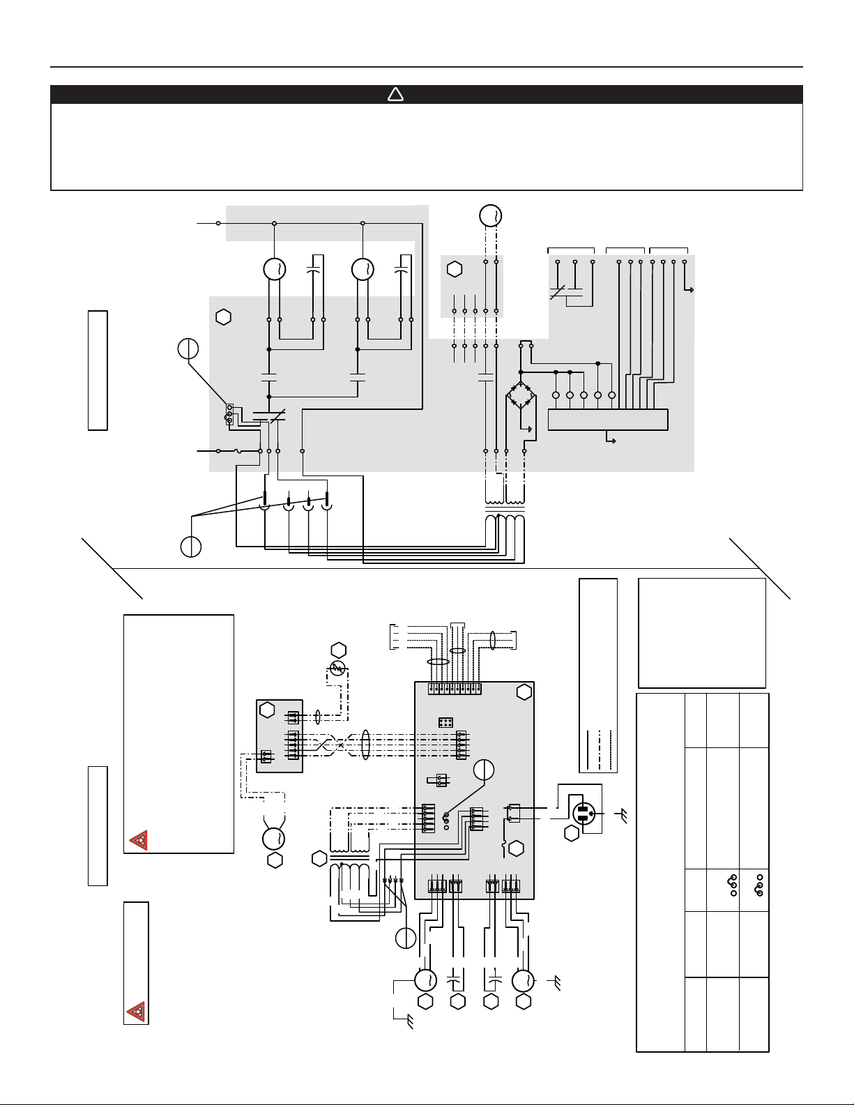
• Risk of electric shocks. Before performing any maintenance or servicing, always disconnect the unit from its power source.
• This product is equipped with an overload protection (fuse). A blown fuse indicates an overload or a short-circuit situation.
If the fuse blows, unplug the product and check the polarity and voltage output from the outlet. Replace the fuse as per the
servicing instructions (refer to wiring diagram for proper fuse rating) and verify the product. If the replaced fuse blows, it may
be a short-circuit and the product must be discarded or returned to an authorized service center for examination and/or repair.
LOGIC DIAGRAM
NOTES
Neutral
J10-1J10-2
120V, 60Hz
2
Ref
HI MED
Line
120 V, 60Hz
1
Ref
A1
321
JU1
K2
F1
B HI
J5-2
capacitor
Exhaust fan motor
Exhaust fan motor
J5-1
J5-3
K1
J9-4
J9-2
J9-1
J9-3
O
MED
O
MED-HI
P
DAMPER
ELECTRONIC ASSEMBLY
A2
1234512
J3
12
BL
J1
J2
MED-LO
J4-2
Supply fan motor
J7-2
J7-1
J4-1
J4-3
K3
R
R LO
R1
Defrost
Field wiring
temperature sensor
t˚
capacitor
Supply fan motor
J6-2
J6-1
YRG
B
remote control
(see notes 3 & 4)
A2
J2-4
J2-5
J12-5
J12-4
Override
switch
987654321
10
J13
ICP
J11
J12
12
Damper motor
J3-2
J3-1
J2-2
J2-1
J2-3
J11-2
J12-2
J12-1
J12-3
K4
J8-1
J8-2
J8-4
9.5 V
24 V
class 2
83 V
68 V
120 V
100 V
notes 3 & 4)
(optional; see
J14
12345
2
Ref
Furnace
blower
interlock
(optional; see
notes 3, 5)
J14-3
J14-1
J14-2
K5
J11-1
K2K4K5
J8-5
class 2
62 V
neutral
J14-1: NO
J14-2: COM
Furnace blower interlock
A1
ASSEMBLY
ELECTRONIC
K1
J14-3: nc
(optional; see notes 3 & 5)
Line voltage factory wiring
Class 2 low voltage factory wiring
Override
switch
J14-4
K3
CPU
(optional; see
notes 3, 4)
J14-5
J14-6
notes 3, 4)
Field wiring
remote
control (see
J14-7
J14-8
J14-9
J14-10
COLOR CODE
B BLACK
BL BLUE
BN BROWN
G GREEN
O ORANGE
P PURPLE
Class 2 low voltage field wiring
R RED
W WHITE
Y YELLOW
nc no connection
J9
J7
C1
capacitor
12
1234
See note 1
12123
J6
B
C2
motor
capacitor
Supply fan
J10
F1
J4
BN
BL
B
M2
motor
Supply fan
W
B
W1
120 V, 60 Hz
G
123
123
JU1
JU1
FAN MOTORS SPEED SELECTION
G
same time. If you do change REF 1 and REF 2 you
will inverse fan motor speeds.
CAUTION: You can change REF 1 or REF 2, but not both at the
Factory shipped
REF 1 ORG REF 1 RED REF2 FAN SPEEDS CFM MAX
ORG to ORG RED to RED HI (120V) & LO (62V) 160
ORG to ORG RED to RED MED-HI (100V) & LO (62V) 140
VE0086A
WIRING DIAGRAM
CONSTRUCTO 1.5V & 90H-V UNITS
B
(3A, 3AG Type).
2. If any of the original wire, as supplied, must
1.
4. Remote controls (class 2 circuit) available,
see instruction manual.
3. Field wiring must comply with applicable
5. Furnace fan circuit must be class 2 circuit only.
codes, ordinances and regulations.
be replaced, use the same equivalent wire.
Use specified UL listed/CSA Certified line fuse
B
M3
Damper motor
T1
Critical characteristic.
120 V
100 V
B
24 V
O
P
class 2
83 V
BL
9.5 V
68 V
R
class 2
W
62 V
neutral
BN
12345
J5
1
Ref
B
Exhaust fan
18
123
J8
12312
BN
BL
M1
motor
JU1
MED HI
BBB
motor
Exhaust fan
BN
Y
Y
nc
nc
G
Page 19
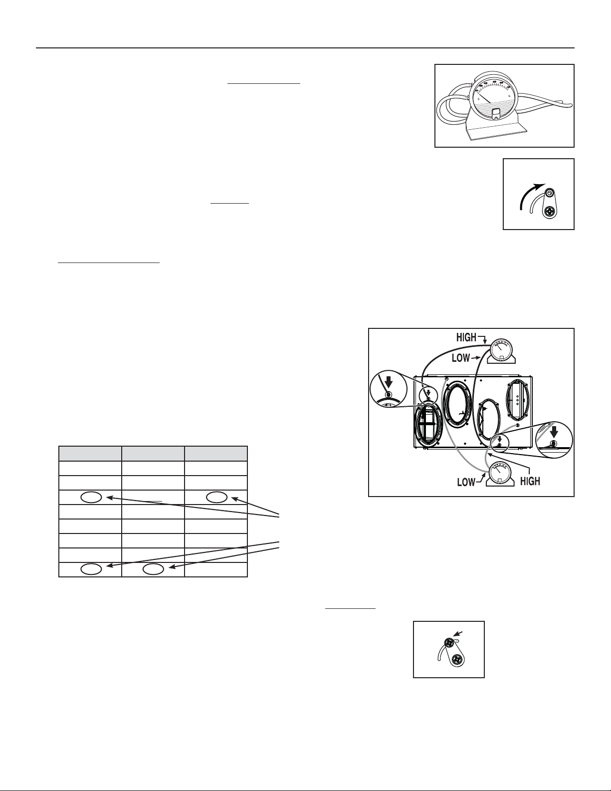
7. BALANCING THE UNIT
7.1 WHAT YO U NEED TO BALANCE THE UNIT
• A magnehelic gauge capable of measuring 0 to 1 inch of water (0 to 249 Pa) and 2 plastic tubes.
• The balancing chart of the unit.
VP0009
7.2 PRELIMINARY STAGES TO BALANCE THE UNIT
• Seal all the unit ductwork with tape. Close all windows and doors.
DAMPER
BALANCING
TOOL
• Turn off all exhaust devices such as range hood, dryer and bathroom fans.
• Make sure the balancing dampers are fully open by setting both damper balancing tools completely vertical.
• Make sure all filters are clean (if it is not the first time the unit is balanced).
VR0029
7.3 BALANCING PROCEDURE
1. Set the unit to high speed.
NOTE: Make sure that the furnace/air handler blower is ON if the installation is in any way connected to the ductwork of the cold air
return. If not, leave furnace/air handler blower OFF. If the outside temperature is below 0°C/32°F, make sure the unit is not
running in defrost while balancing. (By waiting 10 minutes after plugging the unit in, you are assured that the unit is not in a
defrost cycle.)
2. Place the magnehelic gauge on a level surface and adjust it to zero.
3. Connect tubing from gauge to EXHAUST air flow pressure taps (the ones with
arrows, see insets in illustration at right).
Be sure to connect the tubes to their appropriate high/low fittings. If the gauge
drops below zero, reverse the tubing connections.
4. Note the CFM value from balancing chart on unit.
5. Repeat steps 3 and 4, but to FRESH air flow pressure taps.
6. Match highest CFM value to lowest by adjusting the balancing damper
corresponding to the highest value.
See example below:
STALE AIR FLOW
FLOW FRESH EXHAUST
CFM IN. W.G. IN. W.G.
120 0.71 0.73
125
130 0.63 0.67
0.67 0.70
EXHAUST READING VALUES
135 0.59 0.64
140 0.55 0.61
FRESH READING VALUES
145 0.51 0.58
150 0.47 0.55
In that case, there is 150 CFM in FRESH air and 125 CFM in EXHAUST air. Then, adjust (close) the FRESH air balancing damper
until the FRESH air flow matchs the EXHAUST air flow: 125 CFM (0.67 in. w.g.) with magnehelic gauge connected to FRESH air
flow pressure taps).
7. Secure both dampers in place with a fastening screw (included).
8. Write the required air flow information on a label and affix it near the unit for future reference (date, maximum speed air flows, your
name, phone number and business address).
NOTES: 1. Use conversion chart provided with the unit to convert magnehelic gauge readings to equivalent cfm values.
2. The unit is considered balanced even if there is a difference of ±10 cfm (or ± 5 l/s or 17 m³/h) between the two air flows.
VP0017
FRESH AIR FLOW
FASTENING SCREW
VR0030
19
Page 20
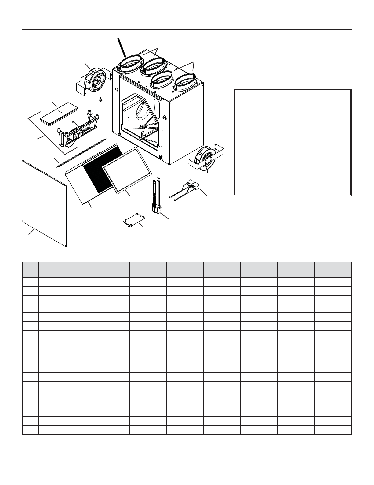
8. SERVICE PARTS
3
4
6
5
2
1
REPLACEMENT PARTS AND REPAIR
In order to ensure your ventilation unit remains
in good working condition, you must use the
manufacturer genuine replacement parts only.
The manufacturer genuine replacement parts
are specially designed for each unit and are
7
manufactured to comply with all the applicable
certification standards and maintain a high
standard of safety. Any third party replacement
8
part used may cause serious damage and
drastically reduce the performance level of
your unit, which will result in premature failing.
The manufacturer recommends to contact
a certified service depot for all replacement
parts and repairs.
8
13
9
12
11
10
VL0036
ITEM DESCRIPTION QTY.
VAL PORT 2 -- 18206 18206 18206 18206 18206
1O
OUBLE COLLAR OVAL PORT 2* 18207 18207 18207 18207 18207 18207
2D
XHAUST DAMPER SPRING 1 18221 18221 18221 18221 18221 18221
3E
OTOR ASSEMBLY 2 18198 18198 18197 18198 18198 18197
4M
ALANCING TOOL 2 18220 18220 18220 18220 18220 18220
5B
EFROST DAMPER 1 18200 18200 18200 18200 18200 18200
6D
DAMPER SYSTEM ASS’Y
7
(INCLUDING ITEM 6)
ORE FILTER 2 18204 18205 18204 18204 18205 18204
8C
H
EAT RECOVERY CORE 1 -- 18202 18203 -- 18202 18203
9
NERGY RECOVERY CORE 1 18042 -- -- 18042 -- --
E
OOR ASSEMBLY 1 18044 18211 18209 18208 18208 18208
10 D
1 18199 18199 18199 18199 18199 18199
ERV
EKO 1.5
11 PCB 1 18216 18216 18215 18216 18216 18215
RANSFORMER 1 18218 18218 18219 18218 18218 18219
12 T
APACITOR 5 μF 2 -- -- 16042 -- -- 16042
13 C
14 THERMISTOR KIT (NOT SHOWN) 1 15749 15749 15749 15749 15749 15749
ARDWARE KIT (NOT SHOWN) 1 08917 08304 08304 08917 08304 08304
15 H
16 PCB C
ONNECTOR (NOT SHOWN) 1 16416 16416 16416 16416 16416 16416
HRV
EKO 1.5
CONSTRUCTO
1.5V
ERV 90H-V
ECM
HRV 90H-V
ECM
90H-V
* Quantity of 4 for ERV EKO 1.5 units only.
20
Page 21
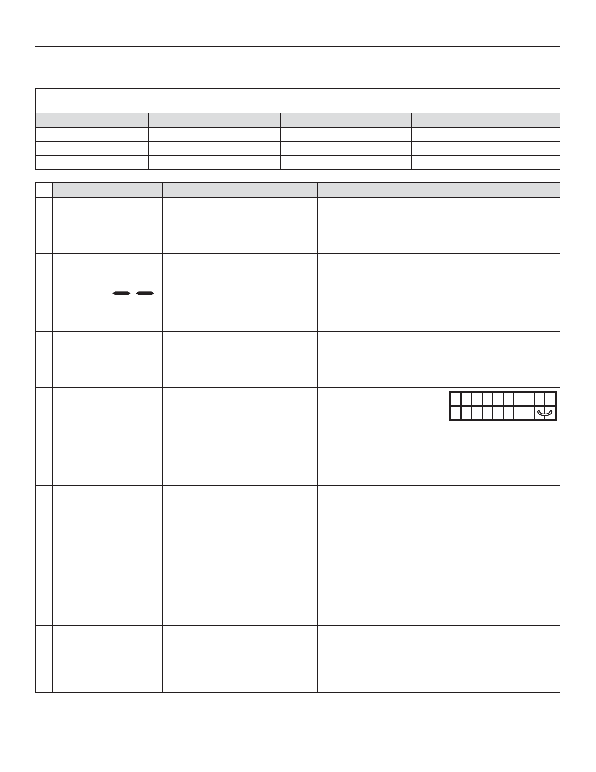
9. TROUBLESHOOTING
If the unit does not work properly, reset the unit by unplugging it for one minute and then replug it. If it still not working properly,
refer to table below.
If the integrated control LED of the unit is flashing, this means the unit sensors detected a problem. See the table below to know where
the problem occurs on the unit.
LED COLOR ERROR TYPE ACTION UNIT STATUS
LED flashes GREEN Thermistor error Replace thermistor Unit works but will defrost frequently
LED flashes AMBER Damper error Go to point 5 Unit does not work
LED flashes RED Motor error Go to point 8 Unit does not work
PROBLEMS POSSIBLE CAUSES YOU SOULD TRY THIS
The error code E1 is
displayed on Altitude,
1
Platinum or Deco-Touch
wall control screen.
There is no outside
temperature displayed on
Altitude or Platinum wall
2
control screen .
Altitude, Platinum or
Deco-Touch wall control
3
screen alternates
between normal display
and E3.
Unit does not work. • The circuit board may be defective.
4
The damper actuator
does not work.
5
The wall control does not
work.
6
• The wires may be in reverse position.
• The wires may be broken.
• The wires may have a bad
connection.
• The unit thermistor may be defective.
• The Altitude, Platinum or Deco-Touch
wall control may be defective.
• The fuse may be defective.
• The damper actuator or the
integrated damper mechanism may
be defective.
• The circuit board or the transformer
may be defective.
• The wires may be in reverse position.
• The wires may be broken.
• The wire in the wall OR the wall
control may be defective.
• Ensure that the color coded wires have been connected to
their appropriate places.
• Inspect every wire and replace any that are damaged.
• Ensure the wires are correctly connected.
NOTE: At its very start-up or after a power failure, it takes
some minutes before the outside temperature appears
on screen. The delay duration depends on which
operation mode the wall control is set. The shortest
delay is obtained when the wall control is set on MIN
or MAX in VENT Mode.
• Replace the unit thermistor.
• Replace the Altitude, Platinum or Deco-Touch wall control.
• Unplug the unit. Disconnect
the main control and the
optional(s) control(s) (if need
be). Jump G and B terminals.
NO C NC I OC OL Y R G B
VE0097
Plug the unit back and wait about 10 seconds. If the motors
run on high speed and the damper opens, the circuit board
is not defective.
• Check if fuse F1 is blown. In that case, replace fuse F1 as
per product nameplate.
• Unplug the unit. Disconnect the main control and the optional
controls(s) (if need be). Wait 10 seconds and plug the unit
back. Check if the damper opens. If not, use a multimeter
and check for 24 VAC on J12-1 and J12-2 (in electrical
compartment). If there is 24 VAC, replace the entire damper
assembly.
NOTE: It is normal to experience a small delay (7-8 seconds)
before detecting the 24 VAC signal at starting-up.
This signal will stay during 17-18 seconds before
disappearing.
• If there is no 24 VAC, check for 24 VAC between J8-1 and
J8-2. If there is 24 VAC, replace the circuit board, and if
there is no 24 VAC, change the transformer.
• Ensure that the color coded wires have been connected to
their appropriate places.
• Inspect every wire and replace any that are damaged.
• Remove the wall control and test it right beside the unit
using another shorter wire. If the wall control works there,
change the wire. If it does not, change the wall control.
21
Page 22
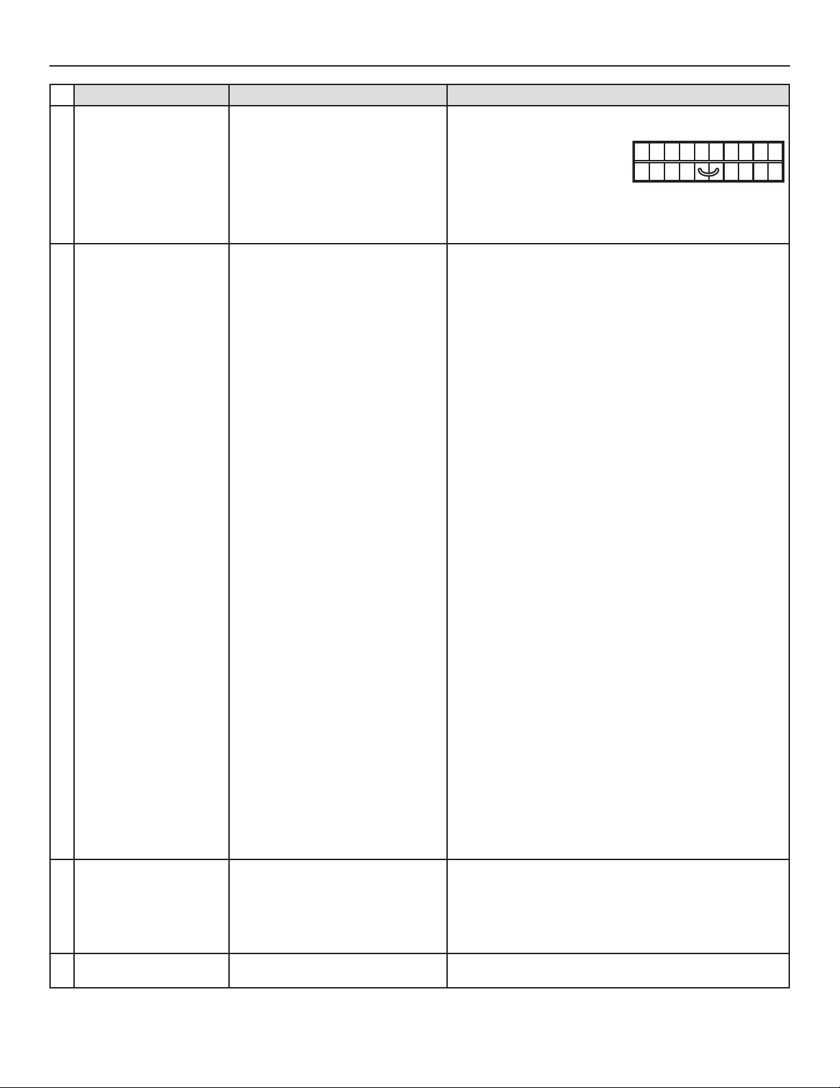
9. TROUBLESHOOTING (CONT’D)
PROBLEMS POSSIBLE CAUSES YOU SOULD TRY THIS
The Dehumidistat
does not work OR the
20-minute push button
timer does not work OR
7
its indicator light does not
stay on.
The supply and/or exhaust
motor do not work.
• The wires may be in reverse postion.
• The Dehumidistat or push button
may be defective.
• The fuse may be defective.
• The jumper JU1 may be in wrong
position or missing.
• Jumper J11 may be missing.
• Ensure that the color coded wires have been connected to
their appropriate places.
• Jump the OL and OC
terminals. If the unit switch
to high speed, remove the
Dehumidistat or push button
and test it right beside the unit using another shorter wire.
If it works here, change the wire. If it doesn’t, change the
Dehumidistat or the push button.
• Check if fuse F1 is blown. In that case, replace fuse F1 as
per product nameplate.
• Make sure that jumper is properly located as per wiring
diagram in Section 6 Wiring diagrams.
• Make sure there is a jumper on connector J11.
NO C NC I OC OL Y R G B
VE0098
8
The defrost cycle does
not work (the fresh air
duct is frozen) OR the
9
fresh air distributed is very
cold.
The integrated control
10
push button does not work.
For ERV and HRV EKO 1.5 and ERV
and HRV 90H-V ECM units only.
• The circuit board or transformer may
be defective.
• The motor(s) may be defective.
For Constructo 1.5V and 90H-V
units only.
• The circuit board or transformer may
be defective.
• The motor(s) or capacitor(s) may be
defective.
• Ice deposits may be hindering the
damper operation.
• The damper rod or the port damper
itself may be broken.
• The damper actuator or circuit board
may be defective.
• The 30-second boot sequence is not
completed.
NOTE: Refer to the Section 6 Wiring diagrams.
• Press on the integrated control push button until the unit
turn on high speed (the LED will light GREEN). Using a
multimeter, check the voltage on J4-1 and J4-2 (for supply
motor), and on J5-1 and J5-2 (for exhaust motor). If both
readings are 120 VAC, the circuit board is not defective. If one
or both readings are not 120 VAC, change the transformer. If
no voltage is present, change the circuit board.
• If the voltage reading is 120 VAC on J4 or J5, change the
defective motor.
NOTE: Refer to the FAN MOTOR SPEED SELECTION
table in Section 6 Wiring Diagrams to know what the
voltage reading must be.
• Press on the integrated control push button until the unit
turn on low speed (the LED will light AMBER). Using a
multimeter, check the voltage on J4-1 and J4-2 (for supply
motor), and on J5-1 and J5-2 (for exhaust motor). Then set
the unit on high speed by pressing on the integrated control
push button one more time (the LED will light GREEN).
Using a multimeter, check the voltage on J4-1 and J4-2 (for
supply motor), and on J5-1 and J5-2 (for exhaust motor). If
all the readings correspond to the right voltage values, the
circuit board is not defective. If one or both readings are
different, change the transformer. If no voltage is present,
change the circuit board.
• Using a multimeter, check the ohms value on each motor
connectors. For BLUE and BLACK motor wires, the right
value is ± 49 ohms. For BLUE and BROWN motor wires,
the right value is ± 79 ohms. For BROWN and BLACK motor
wires, the right value is ± 126 ohms. If the ohms values are
the same, the motor is not defective. Replace the motor
capacitor.
• Remove the ice.
• Inspect these parts and replace if necessary.
• See point 5.
• See Section 4.1 Units Booting Sequence.
22
 Loading...