

Venmar Connaisseur CIC700 Series, CIC700I16WG Installation Instructions Manual
SV09865 rev. 02
CIC700 SERIES
INTENDED FOR DOMESTIC COOKING ONLY
INSTALLER: LEAVE THIS MANUAL WITH HOMEOWNER.
HOMEOWNER: USE AND CARE INFORMATION
ON PAGES 15 TO 18.
Venmar Ventilation Inc., 550 Lemire Blvd., Drummondville QC J2C 7W9
1-800-567-3855
REGISTER YOUR PRODUCT ON LINE AT: www.bnv.ca
For additional information, visit
www.venmar.ca or www.ispira.ca
HB0119
INSTALLATION INSTRUCTIONS
READ AND SAVE THESE INSTRUCTIONS
!
!

WARNING
TO REDUCE THE RISK OF FIRE, ELECTRIC
SHOCK OR INJURY TO PERSONS, OBSERVE
THE FOLLOWING:
1. Use this unit only in the manner intended by the
manufacturer. If you have questions, contact the
manufacturer at the address or telephone number
listed in the warranty.
2. Before servicing or cleaning unit, switch power off
at service panel and lock service disconnecting
means to prevent power from being switched on
accidentally. When the service disconnecting
means cannot be locked, securely fasten a prominent
warning device, such as a tag, to the service panel.
3. Installation work and electrical wiring must be done
by qualified personnel in accordance with all
applicable codes and standards, including
fire-rated construction codes and standards.
4. Sufficient air is needed for proper combustion and
exhausting of gases through the flue (chimney) of
fuel burning equipment to prevent backdrafting.
Follow the heating equipment manufacturer’s
guidelines and safety standards such as those
published by the National Fire Protection
Association (NFPA), and the American Society for
Heating, Refrigeration and Air Conditioning
Engineers (ASHRAE), and the local code authorities.
5. When cutting or drilling into wall or ceiling, do not
damage electrical wiring and other hidden utilities.
6. Ducted fans must always be vented to the outdoors.
7. Do not use this unit with any additional solid-state
speed control device.
8. To reduce the risk of fire, use only metal ductwork.
9. This unit must be grounded. To provide protection
against electric shock, connect to properly grounded
outlets only.
10. All tempered glass can experience spontaneous
breakage. If broken, tempered glass falls out of it’s
opening in interlocking clumps. Tempered glass
can, on occasion, break into large shards rather
than the classic tiny piece pattern.
11. When applicable local regulations comprise more
restrictive installation and/or certification
requirements, the aforementioned requirements
prevail on those of this document and the installer
agrees to conform to these at his own expenses.
TO REDUCE THE RISK OF A RANGE TOP
GREASE FIRE:
a) Never leave surface units unattended at high
settings. Boilovers cause smoking and greasy
spillovers that may ignite. Heat oils slowly on low
or medium settings.
b) Always turn hood ON when cooking at high heat
or when flambeing food (i.e.: Crêpes Suzette,
Cherries Jubilee, Peppercorn Beef Flambé).
c) Clean ventilating fans frequently. Grease should
not be allowed to accumulate on fans, filters or
exhaust ducts.
d) Use proper pan size. Always use cookware
appropriate for the size of the surface element.
!
WARNING
TO REDUCE THE RISK OF INJURY TO PERSONS
IN THE EVENT OF A RANGE TOP GREASE
FIRE, OBSERVE THE FOLLOWING*:
1. SMOTHER FLAMES with a close-fitting lid,
cookie sheet or metal tray, then turn off the burner.
BE CAREFUL TO PREVENT BURNS. IF THE
FLAMES DO NOT GO OUT IMMEDIATELY,
EVACUATE AND CALL THE FIRE DEPARTMENT.
2. NEVER PICK UP A FLAMING PAN – You may be
burned.
3. DO NOT USE WATER, including wet dishcloths
or towels – This could cause a violent steam
explosion.
4. Use an extinguisher ONLY if:
A. You own a Class ABC extinguisher and you
know how to operate it.
B. The fire is small and contained in the area
where it started.
C. The fire department has been called.
D. You can fight the fire with your back to an exit.
*Based on “Kitchen Fire Safety Tips” published by NFPA.
!
- 2 -
CAUTION
1. For indoor use only.
2. For general ventilating use only. Do not use to
exhaust hazardous or explosive materials and
vapors.
3. To avoid motor bearing damage and noisy and/or
unbalanced impeller, keep drywall spray, construction
dust, etc. off power unit.
4. Your hood motor has a thermal overload which will
automatically shut off the motor if it becomes
overheated. The motor will restart when it cools
down. If the motor continues to shut off and
restart, have the hood serviced.
5. The minimum hood distance above cooktop must
not be less than 30”. A maximum of 36” above
cooktop is highly recommended for best capture of
cooking impurities.
6. Two installers are recommended because of the
large size and weight of this hood.
7. To reduce the risk of fire and to properly exhaust
air, be sure to duct air outside – Do not exhaust air
into spaces within walls or ceiling or into attics,
crawl space or garage.
8. Because of the high exhausting capacity of this
hood, you should make sure enough air is
entering the house to replace exhausted air by
opening a window close to or in the kitchen.
9. To reduce the risk of fire and electrical shock, the
Venmar Connaisseur CIC700 Series models
should only be installed with their own built-in
blower.
10. Please read specification label on product for
further information and requirements.
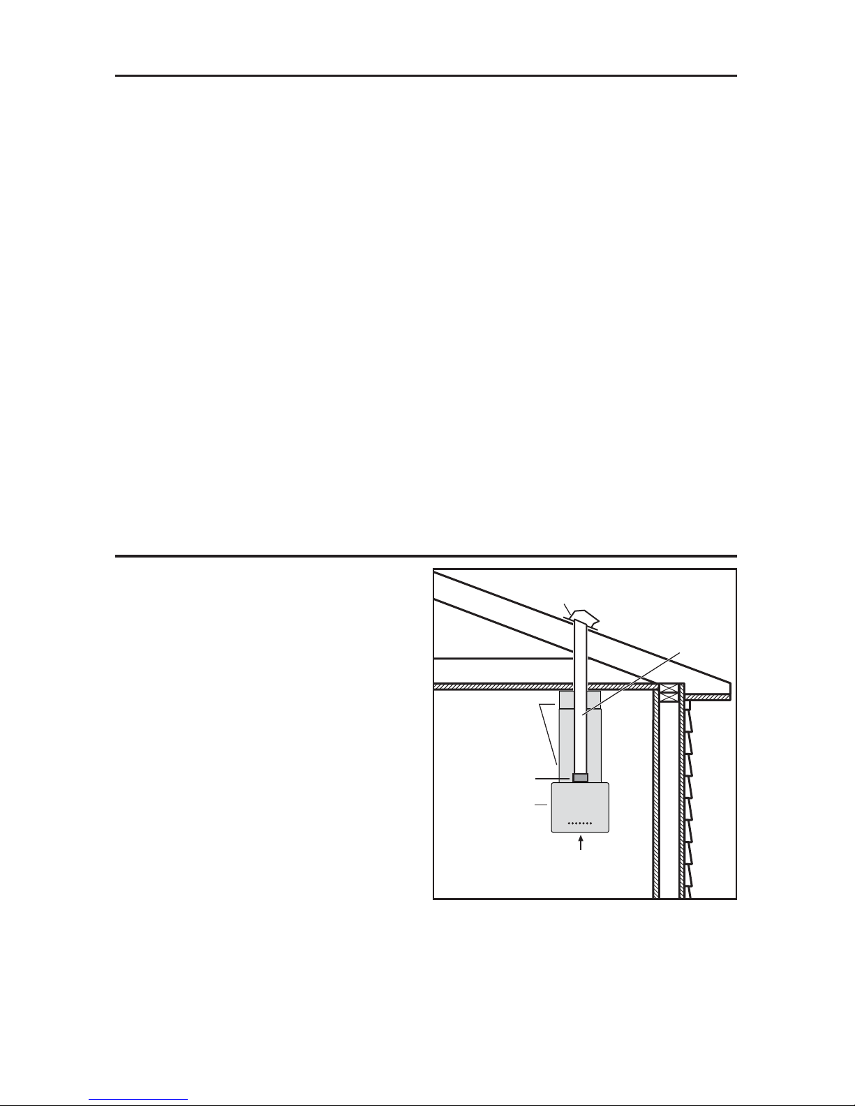
TABLE OF CONTENTS
1. INSTALL DUCTWORK . . . . . . . . . . . . . . . . . . . . . . . . . . . . . . . . . . . . . . . . . . . . . . . .3-4
2. PREPARE THE INSTALLATION . . . . . . . . . . . . . . . . . . . . . . . . . . . . . . . . . . . . . . . . . . . .4
3. PREPARE HOOD . . . . . . . . . . . . . . . . . . . . . . . . . . . . . . . . . . . . . . . . . . . . . . . . . . . . .5
4. M
EASURE INSTALLATION . . . . . . . . . . . . . . . . . . . . . . . . . . . . . . . . . . . . . . . . . . . . . . .6
5. INSTALL MOUNTING BRACKETS . . . . . . . . . . . . . . . . . . . . . . . . . . . . . . . . . . . . . . . . .7-8
6. ASSEMBLE ANGLE BRACKETS . . . . . . . . . . . . . . . . . . . . . . . . . . . . . . . . . . . . . . . . .9-10
7. CONNECT WIRING . . . . . . . . . . . . . . . . . . . . . . . . . . . . . . . . . . . . . . . . . . . . . . . .10-11
8. I
NSTALL GLASS PANELS (WG MODEL ONLY) . . . . . . . . . . . . . . . . . . . . . . . . . . . . . . . . .12
9. INSTALL HOOD . . . . . . . . . . . . . . . . . . . . . . . . . . . . . . . . . . . . . . . . . . . . . . . . . .12-13
10. REINSTALL BAFFLE FILTERS . . . . . . . . . . . . . . . . . . . . . . . . . . . . . . . . . . . . . . . . . . . .14
11. LIGHT BULBS . . . . . . . . . . . . . . . . . . . . . . . . . . . . . . . . . . . . . . . . . . . . . . . . . . . . . .14
12. C
ARE . . . . . . . . . . . . . . . . . . . . . . . . . . . . . . . . . . . . . . . . . . . . . . . . . . . . . . . . . . .15
13. OPERATION . . . . . . . . . . . . . . . . . . . . . . . . . . . . . . . . . . . . . . . . . . . . . . . . . . . .15-18
14. WARRANTY . . . . . . . . . . . . . . . . . . . . . . . . . . . . . . . . . . . . . . . . . . . . . . . . . . . . . . .18
15. WIRING DIAGRAM . . . . . . . . . . . . . . . . . . . . . . . . . . . . . . . . . . . . . . . . . . . . . . . . . .19
16. S
ERVICE PARTS . . . . . . . . . . . . . . . . . . . . . . . . . . . . . . . . . . . . . . . . . . . . . . . . . . . .20
Plan where and how the ductwork will be
installed.
A straight, short duct run will allow the hood to
perform most efficiently.
Install proper-sized ductwork, elbows and roof
cap. Connect metal ductwork to cap and work
back towards the hood location. Use 2” metal foil
duct tape to seal the joints.
Run 3-wire power supply cable to installation
location.
We recommend to install the hood at a minimum
distance of 30” above cooking surface. A maximum
of 36” above cooktop is highly recommended
for best capture of cooking impurities.
NOTES: 1.Distances over 36” are at the installer
and users discretion.
2. 10-ft. ceilings require 10-ft. flue extension,
part no. 19325 (sold separately).
1. INSTALL DUCTWORK
8" ROUND DUCT
ROOF CAP
HOOD
HH0153A
DECORATIVE
FLUE
8" ROUND
ADAPTER
/DAMPER
30" TO 36" ABOVE
COOKING SURFACE
- 3 -

Installation over a gas range:
Refer to gas range manufacturer’s guidelines for
the recommended CFM. If two CIC700 Series
range hoods are required, the minimum space
between the hoods should not be less than 1”.
HH0154A
1" MIN.
- 4 -
1. INSTALL DUCTWORK (CONT’D)
2. PREPARE THE INSTALLATION
When performing installation, servicing or cleaning the unit, it is recommended
to wear safety glasses and gloves.
WARNING
!
NOTE: Before proceeding to the installation, check the contents of the box. If items are missing
or damaged, contact the manufacturer.
Make sure that the following items are included
:
- Hood
- Accessories • Decorative flue assembly (lower and upper flues)
• 2 Shielded halogen bulbs (120 V, 50 W, MR16 with GU10 base)
• 2 Baffle filters
• 4 Filter knobs with screws (taped inside the hood)
• 1 Ceiling mounting bracket
• 8 Angle brackets
• 8” Adapter/Damper (in a separate box)
• Installation manual
• Bag of parts including: 2 wire connectors, 1 wire clamp,
8 no. 10 x 1½" wood screws, 8 washers, 2 no. 8 x 1/2" quadrex screws,
10 no. 8 x 3/8" quadrex screws, 17 no. 10-32 locknuts, 50 no. 10-32 x 1/2"
quadrex screws
Parts sold separately
:
- Ducts, elbows, wall and roof caps.
- Optional flue extension for 10-ft. ceilings model no. 19325.
- LinkLogic® remote control (model no. ACW1WH).
- Glass panels for CIC700I16WG model (see service parts list on page 20).
NOTE: During installation, protect countertop and/or cooktop.

2. Disconnect power cord from electrical box
and disconnect blower.
- 5 -
1. Rest the range hood on a table. Use a piece
of cardboard to avoid damaging the table or
the hood. Remove tape on filters. Lift filters by
pushing them towards the back (opposite
control side) and rotate, then set filters aside.
3. PREPARE HOOD
HO0194
3. Remove blower box 4 retaining screws. Lift
hood and set aside with screws.
HE0125
HD0433
SCREW LOCATIONS

- 6 -
4. MEASURE INSTALLATION
Determine angle brackets length needed
based upon ceiling height (B) and desired
height of hood above cooktop (A).
The table below indicates which flue(s) to use
and the number of brackets required according
to height (C).
HH0156A
C
B
A
CEILING
COOKTOP
BLOWER
BOX
BOTTOM
RANGE HOOD
BOTTOM
93⁄8"
C = B - A - 9
3
⁄8"
C REQUIRED COMPONENTS
FROM TO BRACKETS
UPPER
FLUE
LOWER
FLUE
OPTIONAL
FLUE
BEND
TABS
14¾" 18¾" 4 x
19½" 28¼" 8 x x
28¾" 33" 8 x x x*
33½" 40" 12 x x
40¾" 44¾" 12 x x x*
*
If need be,
bend the 4 tabs
located in the
corners of the
top of the hood,
to a 45° angle
using a straightblade screwdriver
(as illustrated at
right).
HD0445
45°
 Loading...