

Page 1
USER GUIDE
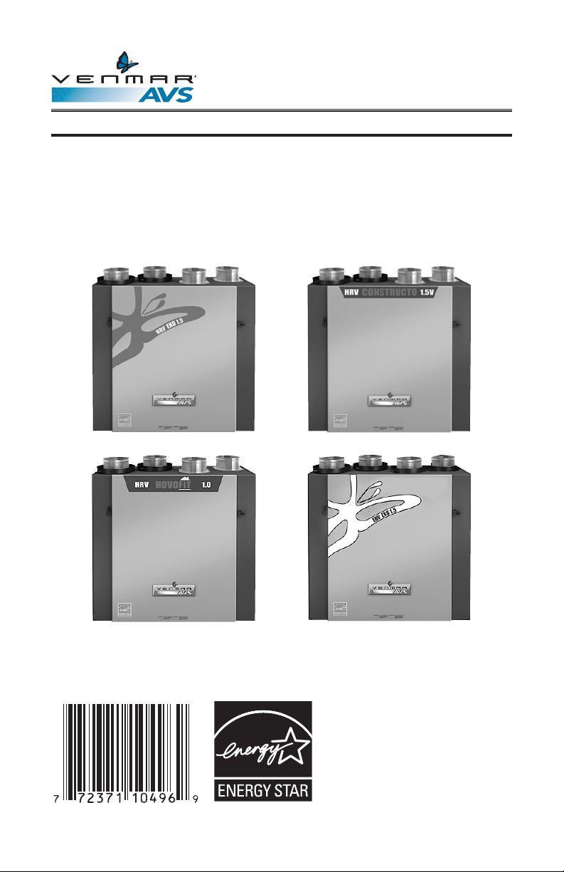
HEAT RECOVERY VENTILATORS MODELS
AVS HRV EKO 1.5, AVS CONSTRUCTO 1.5V,
NOVOFIT 1.0 AND ENERGY RECOVERY
VENTILATOR MODEL AVS ERV EKO 1.5
VB0122 VB0123
VB0126 VB0136
PLEASE READ AND SAVE THESE INSTRUCTIONS
Venmar Ventilation inc., 550 Lemire Blvd., Drummondville, QC, Canada J2C 7W9
www.venmar.ca
These products earned the
ENERGY STAR® by meeting strict
energy efficiency guidelines set by
Natural Resources Canada and the
US EPA. They meet ENERGY STAR
requirements only when used in
Canada.
08445 rev. 05
Page 2
Congratulations!
You have made an excellent choice! The operating principle of your Heat Recovery Ventilator
or your Energy Recovery Ventilator will give you personal comfort you have never known
before.
We have prepared this User Guide especially for you. Please read it carefully to ensure you
obtain full benefit from your unit. Over the coming months, you will increasingly appreciate the
feeling of living in a more comfortable house.
Please take note that this manual uses the following symbols to emphasize
particular information:
!
WARNING
Identifies an instruction which, if not followed, might cause serious
personal injuries including possibility of death.
CAUTION
Identifies an instruction which, if not followed, may severely damage the
unit and/or its components.
NOTE: Indicates supplementary information needed to fully complete an instruction.
We welcome any suggestions you may have concerning this guide and/or the unit, and we
would appreciate hearing your comments on ways to better serve you.
Please forward all correspondence to us at the address indicated on the product registration
card included with this guide.
CAUTION
Make sure at all times that the outside intake and exhaust hoods are free
from any snow during the winter season. It is important to check your unit
during a big snow storm, so it doesn’t draw in any snow. If this is the case,
please operate the unit in the recirculation mode, or turn it OFF for a few
hours.
Do not use your unit during construction or renovation of your house or
when sanding drywall. This type of dust may damage your system.
Since the electronic control system of the unit is incorporated with a
microprocessor, it may not operate correctly because of external noise
or very short power failure. If this happens, unplug the unit and wait
approximately 10 seconds. Then, plug the unit in again.
2
Page 3

TABLE OF CONTENTS
1. DEFROSTING MODE . . . . . . . . . . . . . . . . . . . . . . . 4
ONTROLS. . . . . . . . . . . . . . . . . . . . . . . . . . . 4-17
2. C
2.1 BOOTING SEQUENCES . . . . . . . . . . . . . . . . . . . . . . . . 4
2.2 INTEGRATED CONTROL . . . . . . . . . . . . . . . . . . . . . . . . 5
2.3 ALTITUDE MAIN CONTROL . . . . . . . . . . . . . . . . . . . . . 6-11
2.4 DECO-TOUCH MAIN CONTROL . . . . . . . . . . . . . . . . . . .12-14
2.5 LITE-TOUCH CONSTRUCTO MAIN CONTROL . . . . . . . . . . . . . . 15
2.6 CONSTRUCTO MAIN CONTROL . . . . . . . . . . . . . . . . . . . . 16
2.7 OPTIONAL AUXILIARY CONTROLS . . . . . . . . . . . . . . . . . . 16-17
2.7.1 20-MINUTE LIGHTED PUSH BUTTON . . . . . . . . . . . . . . . . . . . 16
2.7.2 20/40/60-MINUTE PUSH-BUTTON TIMER . . . . . . . . . . . . . . . . . 17
2.7.3 DEHUMIDISTAT . . . . . . . . . . . . . . . . . . . . . . . . . . . . . 17
2.7.4 60-MINUTE CRANK TIMER . . . . . . . . . . . . . . . . . . . . . . . . 17
3. MAINTENANCE . . . . . . . . . . . . . . . . . . . . . . . . 18-19
3.1 SEMI-ANNUAL MAINTENANCE. . . . . . . . . . . . . . . . . . . . 18-19
3.2 ANNUAL MAINTENANCE . . . . . . . . . . . . . . . . . . . . . . . 19
4. TROUBLESHOOTING . . . . . . . . . . . . . . . . . . . . . . 19-20
3
Page 4
1. DEFROSTING MODE
When the outside temperature is below -5°C (23°F), recovery of heat in HRV units creates
frost in the core. For ERV units, when the outside temperature is below -10°C (14°F), recovery
of energy creates frost in the core.
To maintain its proper operation, the unit is programmed to defrost the recovery core. The
defrost frequency varies according to the outside temperature.
During the defrost cycle, the unit shifts to maximum speed and the dampers close.
After defrosting, the unit returns to the operating mode selected by the user.
2. CONTROLS
2.1 BOOTING SEQUENCES
BOOTING SEQUENCE (HRV EKO 1.5 AND ERV EKO 1.5 ONLY)
The unit booting sequence is similar to a personal computer booting sequence.
Each time the unit is plugged after being unplugged, or after a power failure, the unit will
perform a 30-second booting sequence before starting to operate.
During the booting sequence, the integrated control LED will light AMBER for 10 seconds.
After that, the LED will light RED for the rest of the booting sequence. During this RED light
phase, the unit is checking and resetting the motorized damper position.
Once the motorized damper position completely set, the RED light turns off and the booting
sequence is done.
NOTE: No command will be taken until the unit is fully booted.
BOOTING SEQUENCE (CONSTRUCTO 1.5V AND NOVOFIT 1.0 ONLY)
The unit booting sequence is similar to a personal computer booting sequence.
Each time the unit is plugged after being unplugged, or after a power failure, the unit will
perform a 30-second booting sequence before starting to operate.
During the booting sequence, the integrated control LED will light GREEN (unit set in
normal defrost) or AMBER (unit set in extended defrost) for 5 seconds, and then will shut
off for 2 seconds. After that, the LED will light RED for the rest of the booting sequence.
During this RED light phase, the unit is checking and resetting the motorized damper
position.Once the motorized damper position completely set, the RED light turns off and
the booting sequence is done.
NOTE: No command will be taken until the unit is fully booted.
4
Page 5
2. CONTROLS (CONT’D)
2.2 INTEGRATED CONTROL
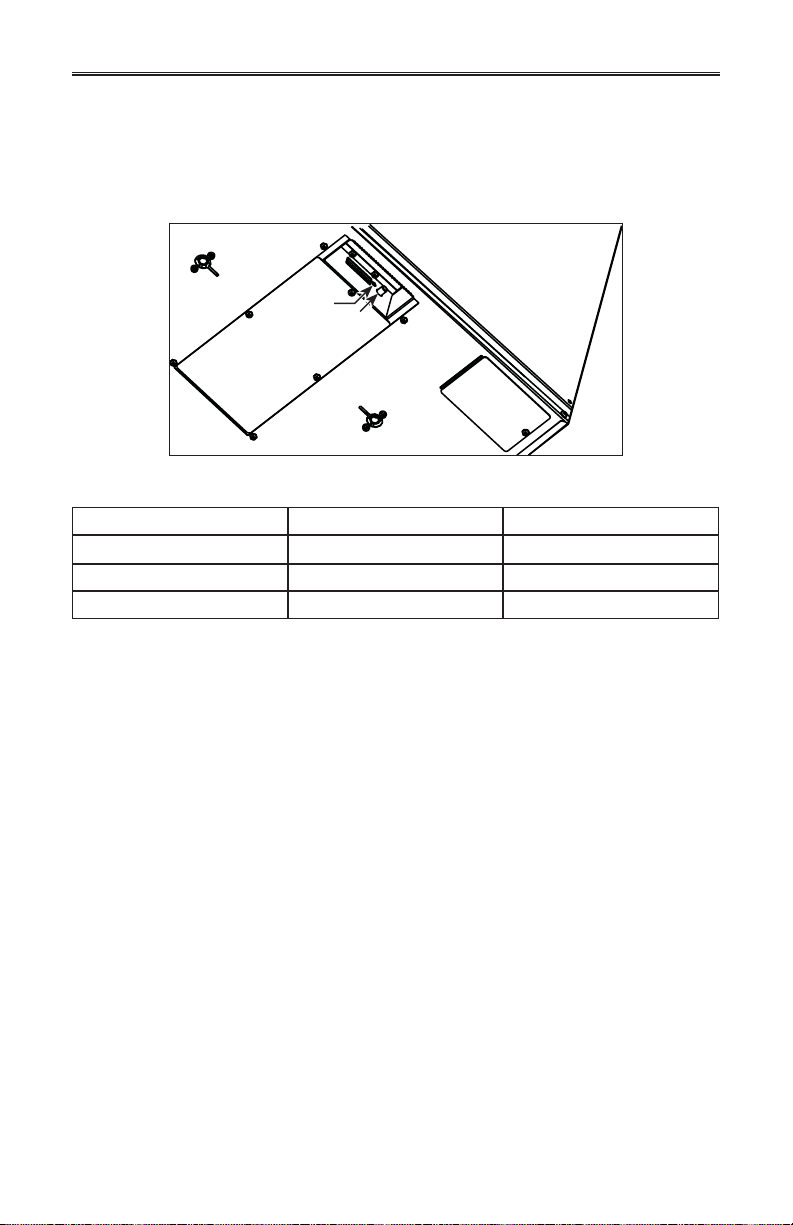
All units are equipped with an integrated control, located under the unit, on the recessed side
of electrical compartment. Plug the unit. Use the push button (1) to control the unit. The LED (2)
will then show on which mode the unit is in.
2
1
VD0207
Refer to table below to see how to operate the unit using its integrated control.
PRESS ON PUSH BUTTON LED COLOR RESULTS
ONCE
TWICE GREEN UNIT IS ON HIGH SPEED
THREE TIMES NO LIGHT UNIT IS OFF
If a problem occurs during the unit operation, its integrated control LED (2) will blink. The color
of the blinking light depends on the type of error detected. Refer to Section 4 Troubleshooting
on last page for further details.
NOTE: When using main control, the integrated control must be turned off.
BOTTOM OF THE UNIT
AMBER UNIT IS ON LOW SPEED
5
Page 6
2. CONTROLS (CONT’D)
2.3 ALTITUDE MAIN CONTROL (FOR AVS HRV EKO 1.5,
AVS ERV EKO 1.5 AND NOVOFIT 1.0 UNITS ONLY)
For more convenience, these units can also be controlled using a main control.
Only one main control can be connected per unit.
NOTES: 1. The integrated control must be turned OFF to use a main control.
2. If an optional auxiliary control is used, if activated, this auxiliary control will
override the optional main control
ALTITUDE WALL CONTROL KEYS AND INDICATORS
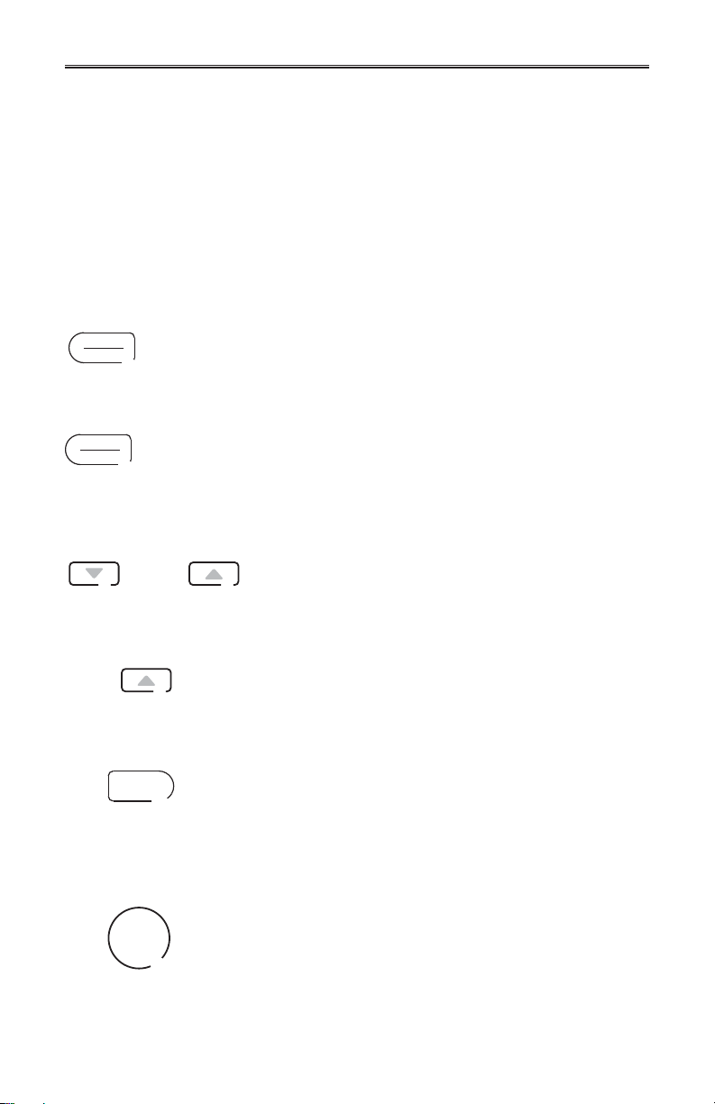
MODE/PREF KEY
.
MODE
PREF
MODE
PREF
3 SEC.
OR
8 SEC.
SET
Press this key to select whether Ventilation mode (air exchange with
the outside), Recirculation mode (air recirculation within the house) or
Program mode (the operation of the ventilation unit is customized by the
user. Refer to HOW TO SET PERIODS FOR PROGRAM MODE section).
Press and hold this key for 3 seconds to access Preference setting menu.
ARROW KEYS
Use the arrow keys to:
• Select ventilation and recirculation speeds.
• Review the programmed periods.
• Select Preference and Program values.
Press on Up arrow key for 8 seconds to display interior
relative humidity level (in percentage).
SET KEY
Press and hold this key for 3 seconds to access setting periods for
Program Mode.
Press this key to confirm the chosen option and go to the following
setting.
SMART
SMART KEY
Press this key to enable and disable the SMART mode.
The SMART mode uses indoor relative humidity level and
minimum and maximum outside temperature values to manage
the air exchange with the outside, in order to enhance comfort in
the house.
6
Page 7
2. CONTROLS (CONT’D)
SET
MODE
PREF
BOTH DURING
5 SEC.
2.3 ALTITUDE MAIN CONTROL (FOR AVS HRV EKO 1.5,
AVS ERV EKO 1.5 AND NOVOFIT 1.0 UNITS ONLY) (CONT’D)
ALTITUDE WALL CONTROL KEYS AND INDICATORS (CONT’D)
POWER INDICATOR
This indicator, located in the upper left side of the wall control,
illuminates when the control powered on.
FILTER MAINTENANCE INDICATOR
This indicator, located in the upper right side of the wall control,
illuminates when it is time to perform the ventilation unit filter
maintenance (refer to the ventilation unit user guide).
Once the filter maintenance is done, reset the filter maintenance
indicator as follow:
Press simultaneously on both MODE/PREF key
and SET key for 5 seconds to turn off the filter
maintenance indicator light.
7
Page 8
2. CONTROLS (CONT’D)
2.3 ALTITUDE MAIN CONTROL (FOR AVS HRV EKO 1.5,
AVS ERV EKO 1.5 AND NOVOFIT 1.0 UNITS ONLY) (CONT’D)
HOW TO SET PREFERENCES
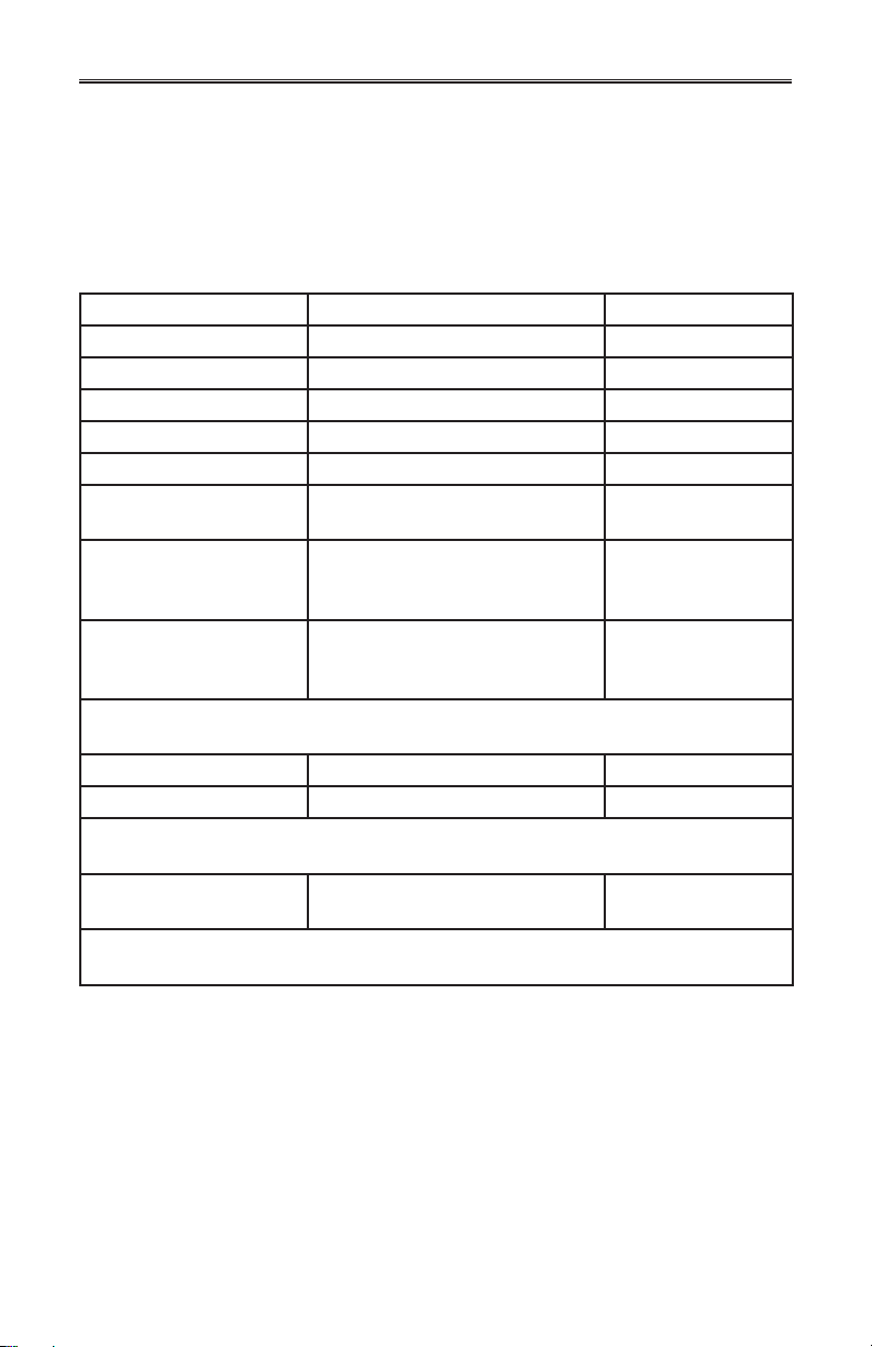
In order to benefit from all of the features of your wall control, the preferences must
be set. Table below shows all available settings.
SETTING AVAILABLE VALUES DEFAULT OPTION
CURRENT DAY MON/TUE/WED/THU/FRI/SAT /SUN MON
HOUR DISPLAY 12:00
AM
OR 24:00 12:00
PM PM
CURRENT HOUR FROM 0 TO 12 OR 24 12
URRENT MINUTE FROM 00 TO 59 00
C
EMPERATURE UNIT °C OR °F °C
T
NSIDE
I
TEMPERATURE DISPLAY
INIMUM OUTSIDE
M
TEMPERATURE
AIR EXCHANGE*
FOR
AXIMUM OUTSIDE
M
TEMPERATURE
AIR EXCHANGE*
FOR
N PROG OR SMART MODE, THESE LIMIT VALUES ALLOW TO STOP AIR EXCHANGE WITH
*I
THE OUTSIDE FOR BETTER COMFORT IN THE HOUSE.
ACKLIGHT COLOR BLUE OR GREEN BLUE
B
ON OR OFF ON
-40°C TO 0°C
OR
-40°F TO 32°F
1°C TO 40°C
OR
33°F TO 104°F
BACKLIGHT DISPLAY AUTO OR ON AUTO
AUTO: B
ACKLIGHT ACTIVATED 10 SECONDS WHEN ANY KEY IS PRESSED.
ON: BACKLIGHT ALWAYS ON.
MODE FOR
OFF
INTERMITTENT MODE
FTER A VENTILATION PERIOD, DETERMINES THE SECOND PAR T OF THE CYCLE
A
VENTILATION/RECIRCULATION
VENTILATION/OFF
OR
VENT/RECIRC.
(RECIRCULATION OR OFF).
AM
-25°C
OR
-13°F
27°C
OR
81°F
8
Page 9
2. CONTROLS (CONT’D)
2.3 ALTITUDE MAIN CONTROL (FOR AVS HRV EKO 1.5,
AVS ERV EKO 1.5 AND NOVOFIT 1.0 UNITS ONLY) (CONT’D)
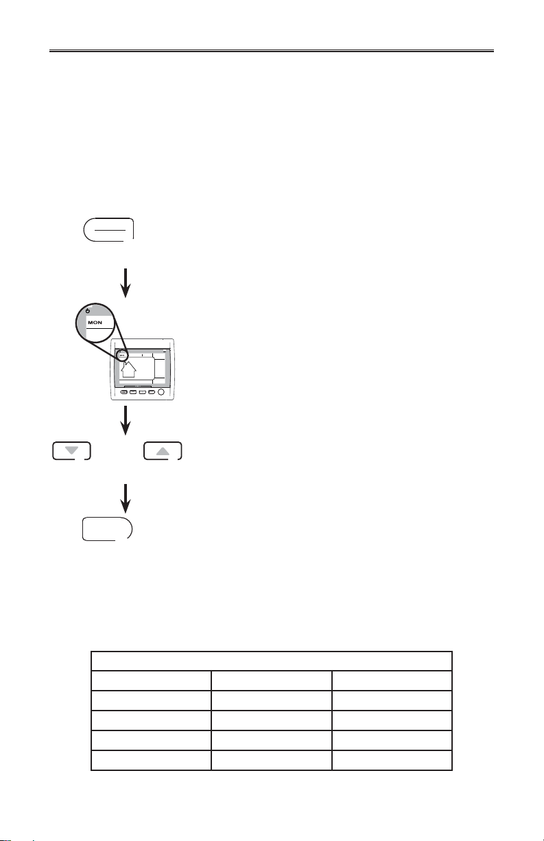
SETTING PREFERENCES PROCEDURE
NOTE: While setting Preferences, the corresponding setting value flashes
(e.g.: while setting current hour, hour is flashing).
Press and hold MODE/PREF key for 3 seconds to access
MODE
PREF
3 SEC.
MODE
SET
SMART
PREF
the setting menu.
NOTE: You can exit Preferences setting by pressing
on MODE/PREF for 3 seconds any time in the
process, or wait 60 seconds. The modified values
will be kept in memory.
If the control is set for the very first time, the current day
will be the first setting to be made: MON (for Monday) will
flash on screen.
OR
SET
Use the arrow keys to select value.
Press SET key to confirm the selected preference and
go to next setting.
HOW TO SET PERIODS FOR PROGRAM MODE
The Program Mode allows the user to customize the operation of his/her ventilation unit, for
week and weekend days. All days are divided in 4 periods. The periods starting hour and
ventilation speed are factory set (see below).
DAILY PERIODS DEFAULT SETTINGS
PERIOD STARTING HOUR MODE
PERIOD 1 (MORNING) 6:00 AM MIN
ERIOD 2 (DAY) 9:00 AM 20 MIN/H
P
PERIOD 3 (EVENING) 5:00 PM MIN
ERIOD 4 (NIGHT) 11:00 PM 20 MIN/H
P
9
Page 10
2. CONTROLS (CONT’D)
2.3 ALTITUDE MAIN CONTROL (FOR AVS HRV EKO 1.5,
AVS ERV EKO 1.5 AND NOVOFIT 1.0 UNITS ONLY) (CONT’D)
HOW TO SET PERIODS FOR PROGRAM MODE (CONT’D)
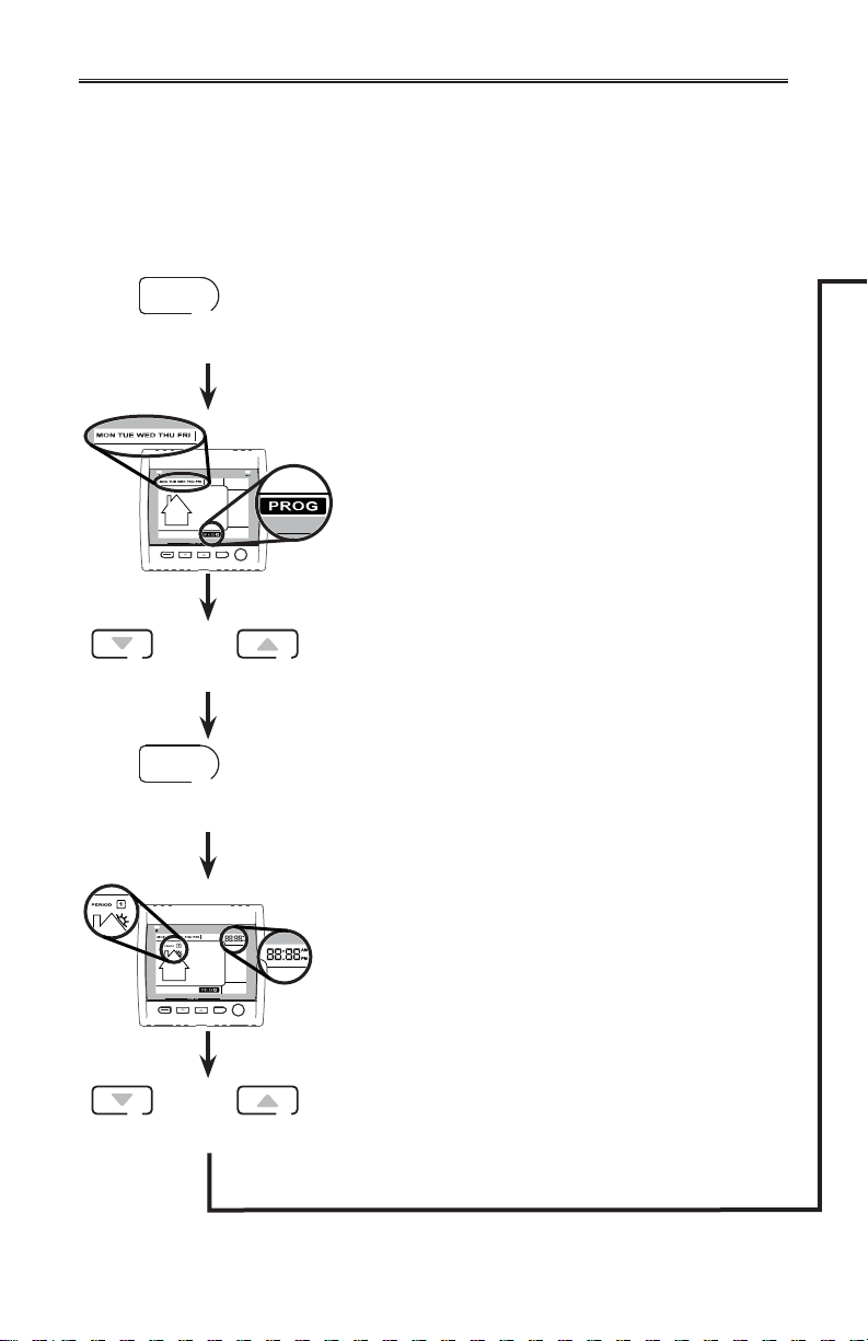
TO CHANGE THESE VALUES:
SET
3 SEC.
MODE
PREF
OR
SET
Press SET key for 3 seconds.
PROG (for Program) will appear on screen and week
days will flash.
NOTE: If the week days were the first to be set, the
weekend days will appear on screen; but if the
weekend days were the first to be set, then the
SET
SMART
week days will appear on screen.
Use the arrow keys to select between week days or
weekend days.
Press SET key to confirm the choice and go to setting
daily period 1.
MODE
PREF
OR
Period 1 will appear on screen and hour display will flash.
SET
SMART
Use the arrow keys to select the period starting hour.
NOTE: Time changes by 15 minutes increments.
10
Page 11
2. CONTROLS (CONT’D)
2.3 ALTITUDE MAIN CONTROL (FOR AVS HRV EKO 1.5,
AVS ERV EKO 1.5 AND NOVOFIT 1.0 UNITS ONLY) (CONT’D)
HOW TO SET PERIODS FOR PROGRAM MODE (CONT’D)
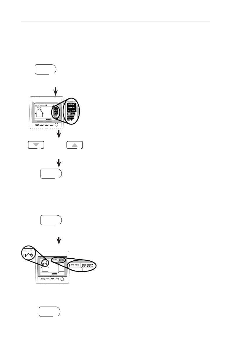
SET
Press SET key to confirm the choice and go to select the
ventilation speed or type.
Ventilation speeds and type will flash.
MODE
SET
PREF
SMART
OR
Use the arrow keys to select the ventilation speed or
type.
SET
Press SET key to confirm the choice and go to setting
daily period 2.
Period 2 will appear on screen and hour display will flash. Proceed as for Period 1 for all daily
periods. Once the ventilation speed or type for Daily Period 4 has been selected:
SET
Press SET key to confirm and go to weekend days.
Weekend days and period 1 will appear on screen and
hour will flash.
MODE
SET
PREF
SMART
Set weekend days periods as for week days.
TO EXIT SETTING PERIODS
SET
Press SET key for 3 seconds.
3 SEC.
11
Page 12
2. CONTROLS (CONT’D)
2.4 DECO-TOUCH MAIN CONTROL (ALL UNITS)
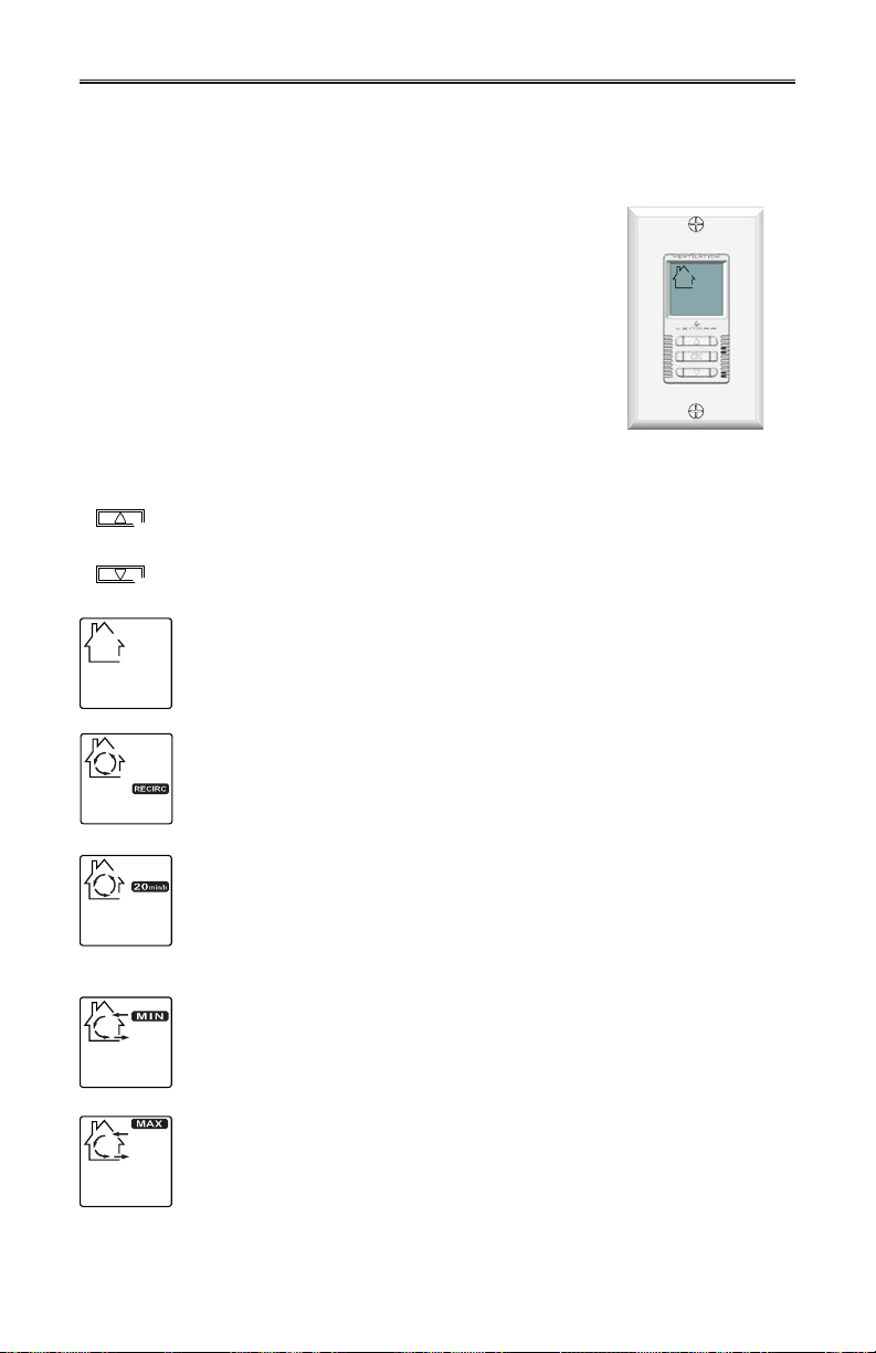
If the backlight is not illuminated, the first button pressed (no
matter which button) shall turn on the backlight. The backlight
remains illuminated for 10 seconds after the last button pressed.
OPERATING MODES
To change the operation modes of the ventilation unit, press the UP or DOWN
BACKLIGHT
OR
arrow button. Operating mode label will then scroll up or down on LCD screen.
Put the unit on stand-by mode, so it will only respond to override wall controls
(if present). On LCD screen, only the House is visible showing the control is
powered on. This is the factory default mode.
Air is recirculated inside the house at high speed.
NOTE: This mode is not available for HRV Constructo 1.5V.
The ventilation unit exchanges air intermittently on a one hour cycle as
follows: OFF for 40 min. (or recirculation* on high speed for 40 min., see next
page) and then exchange air during 20 min. on low speed. Repeat cycle after
the 20 min. of air exchange.
*Except for HRV Constructo 1.5V.
OFF
RECIRC
20 MIN/H
VC0119
Air is exchanged with the outside on low speed.
Air is exchanged with the outside on high speed.
MIN
MAX
12
Page 13
2. CONTROLS (CONT’D)
2.4 DECO-TOUCH MAIN CONTROL (ALL UNITS) (CONT’D)
HOW TO SET THE RELATIVE HUMIDITY (RH) LEVEL AND CHOOSE BETWEEN OFF IN
STAND BY OR RECIRCULATION IN STAND BY*
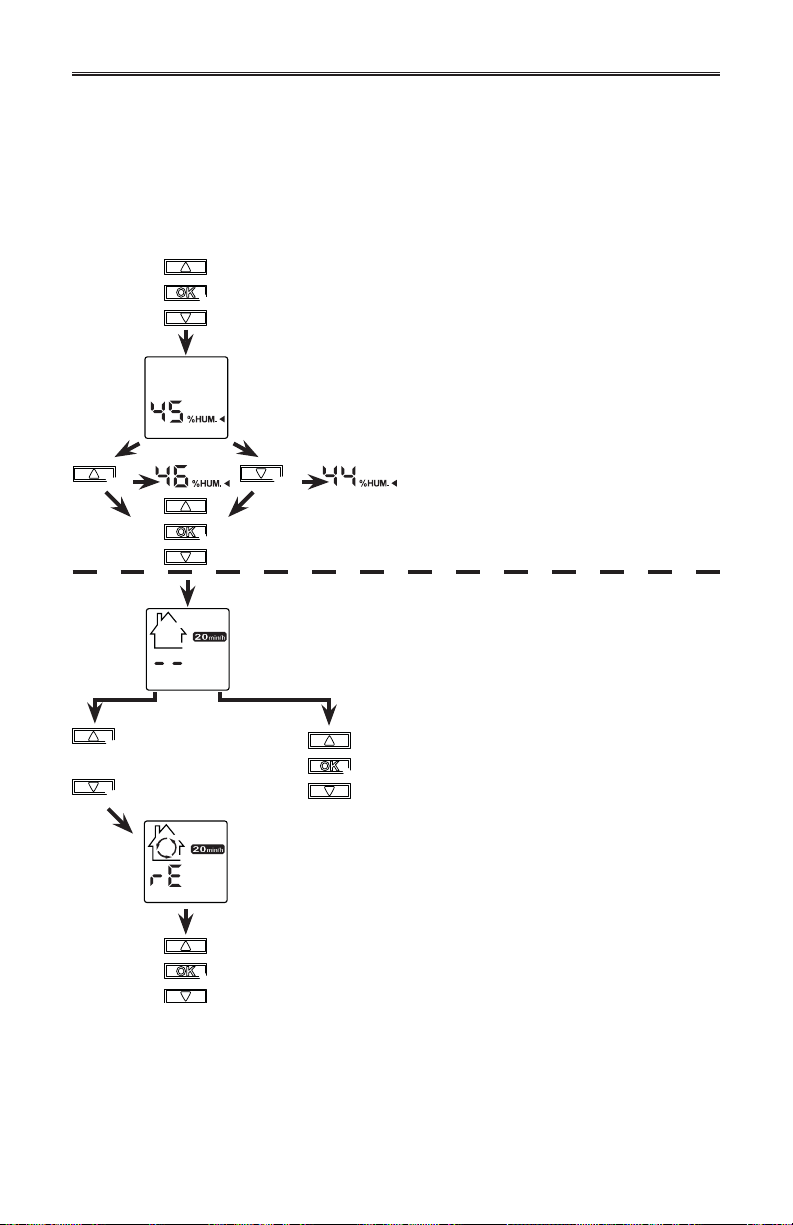
Setting the relative humidity level allows to select the maximum desired indoor humidity level
(in percentage). This value will be used to start the dehumidistat override (air exchange on
high speed).
3 sec.
OR
Press and hold OK for 3 sec. to access the setting menu.
The backlight will be activated during all the procedure.
The relative humidity arrow and value will flash
(default setting: 45%).
Use UP or DOWN arrow to change the value.
The value changes by 1% increments.
Lower value: 30%. Higher value: 55%. Still
flashing.
Press OK button to accept new value and go to next setting.
NOTE: For HRV Constructo 1.5V, press OK button to accept
new value and quit setting menu.
Two lines are flashing to show that
OFF¹ is in standby
(default configuration setting).
OR
Use UP or DOWN
OR
¹OFF IN STANDBY*: On 20 min./h. mode, the ventilation unit is OFF during 40 minutes and
RECIRCULATION
*OFF in standby and RECIRCULATION in standby are not available for HRV Constructo 1.5V units.
arrow to change
to recirculation in
standby.
Recirculation arrows are turning and rE
flashes to show that RECIRCULATION²
is in standby.
Press OK button to accept and
quit setting menu.
exchanges air with the outside on low speed during the remaining
20 minutes of the hour; this is the default value.
IN STANDBY*: On 20 min./h. mode, the ventilation unit recirculates the inside
air for 40 min. on high speed and exchanges air with the
outside on low speed during the remaining 20 min. of the hour.
Press OK button to accept and
quit setting menu.
13
Page 14
2. CONTROLS (CONT’D)
2.4 DECO-TOUCH MAIN CONTROL (ALL UNITS) (CONT’D)
DEHUMIDISTAT OVERRIDE SELECTION
In the operating modes MIN, MAX, 20 min./h. and RECIRC (if available), the user can select a
dehumidistat override so that if the relative humidity (RH) in the house exceeds the RH setting
previously stored, the ventilation unit will exchange in high speed until the target indoor RH
setting is reached.
An air exchanger is not a dehumidifier, but it can change the indoor relative humidity
by bringing in drier or more humid air from outside during non heating season.
The dehumidistat override function is useful to reduce indoor RH when the outdoor
air is cool and dry during the heating season. Select a target RH between 30% and 55%
according to your comfort. When outdoor relative humidity is high (e.g. in summer), turn off
the override by pressing OK until the RH display disappears.
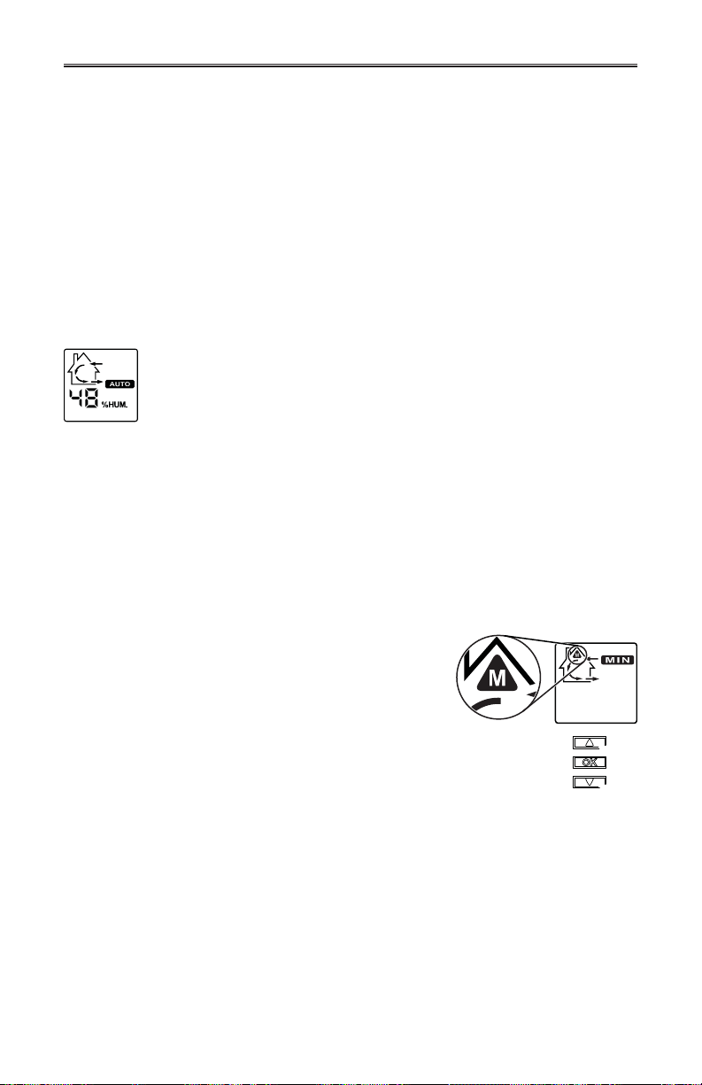
When the dehumidistat override is activated, the AUTO indicator will appear on LCD
screen to show that the actual mode is being overridden. Also, the relative humidity
appears (if it was not shown, see example beside). Once the target humidity level is
reached, the unit goes back into its original operating mode and AUTO disappears
from LCD screen.
NOTE: If the actual mode is MAX, only the relative humidity level appears on screen, AUTO
label willl not appear.
To engage the humidity override, press OK. The actual indoor RH and the %HUM label
appear on LCD screen.
NOTE: If the actual RH is less than 20%, then the humidity indicator will display “LO”, and if
the actual RH is greater than 80%, then the humidity indicator will display “HI”.
To turn off the dehumidistat override, press OK again. The RH and %HUM display will disappear
from LCD screen.
MAINTENANCE INDICATOR
The maintenance indicator is represented by an M in a rounded
triangle, at the top of the house (see at right). If this indicator
is flashing, perform the regular maintenance, and if it is not
flashing, perform the annual maintenance (refer to Section 3).
RESETTING MAINTENANCE INDICATOR: Press simultaneously on both arrow buttons,
maintenance indicator will disappear from LCD
screen.
AND
POWER FAILURE
After a power failure, the wall control returns to its original operation mode. All settings are
kept in memory.
14
Page 15
2. CONTROLS (CONT’D)
2.5 LITE-TOUCH CONSTRUCTO MAIN CONTROL
(FOR HRV CONSTRUCTO 1.5V UNIT ONLY)
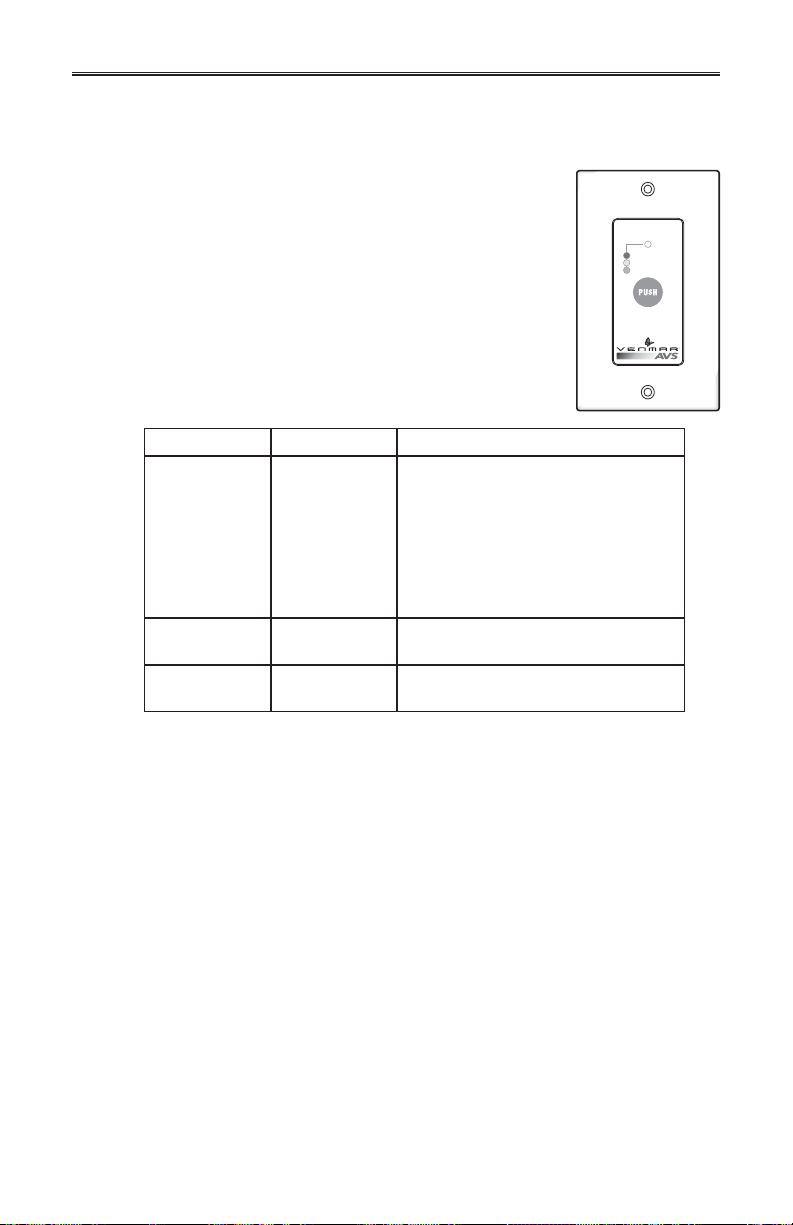
Activate the push button; the color of the indicator shows the
unit operating mode.
Color Mode Suggested Use
GREEN Intermittent Select this mode when you are away
YELLOW Min Speed
Ventilation
RED Max Speed
Ventilation
from the house for a few days. Also,
when you deem the inside air is too
dry in heating season, or too humid
during cooling season. In this mode,
the unit is OFF for 40 minutes per hour
and ventilates at minimum speed the
remaining 20 minutes of the hour.
For normal daily operation.
For excess pollutants and humidity
(parties, odors, smoke, etc.)
VC0075
MAX
MIN
INTERMITTENT
L-T
15
Page 16
2. CONTROLS (CONT’D)
2.6 CONSTRUCTO MAIN CONTROL (FOR HRV CONSTRUCTO 1.5V UNIT ONLY)
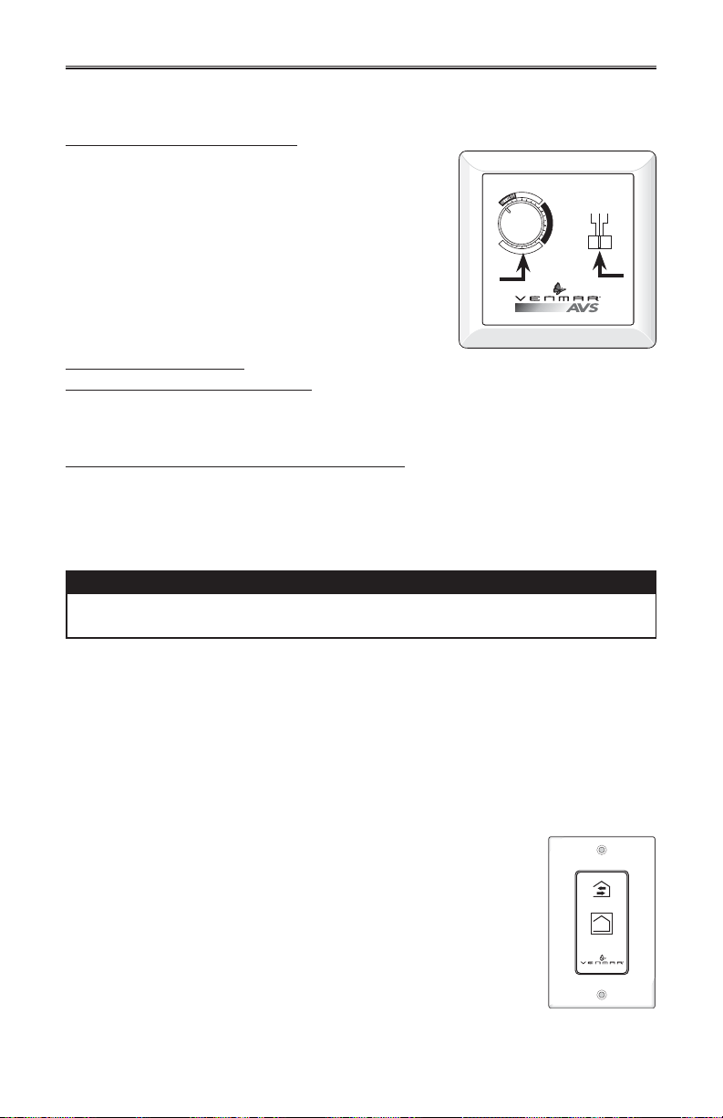
Adjusting AIR SUPPLY CONTROL
1) Select “MIN” or “MAX” using slide switch (A).
• When “MIN” (minimum speed) is selected, if the knob (B)
is set above the click, the unit will exchange in low
speed with the outside and if it is set below the click,
the unit will exchange on high speed with the outside
until the desired humidity level has been reached.
• When “MAX” (maximum speed) is selected, the unit will
B
exchange on high speed with the outside either if the
knob is set below or above the click.
CONSTRUCTO
2) To turn off the unit, slide the switch at the “OFF” position.
Adjusting DEHUMIDISTAT
VC0086
Setting during the summer months:
During this period, unless being afflicted with breathing problems, using the Dehumidistat is
unnecessary. Set the slide switch to “OFF”. (Do not exchange in day time; exchange at night
time, if cool outside, or if it is not raining.)
Setting during the fall, winter and spring months:
(When severe condensation appears on windows)
1) Determine the humidity level in your house (bring the knob (B) counterclockwise to its
maximum position, then bring it back clockwise slowly until you hear a “click”).
2) Set the knob to one line under this temperature level or “click”.
CAUTION
Do not select a temperature below -20°C (-4°F). This could lead to excessive
dryness in the air causing discomfort for the occupants.
It is possible (and normal) to experience condensation on your windows when drastic
changes in temperature happen (for example: -5°C [23°F] to -20°C [-4°F]). In that case,
we suggest waiting a few days to allow the situation to stabilize.
C
°
5
F
°
41
E
X
X
X
X
X
#
0
1
/
9
--5°C
8
OFF
MIN MAX
N
O
Z
T
R
O
F
23°F
M
O
C
-20°C
-4°F
A
2.7 OPTIONAL AUXILIARY CONTROLS
Contrary to the main controls, up to 5 optional auxiliary controls can be connected to the
same ventilation unit.
Press once to activate the push button. The unit will
operate on high speed for 20 minutes and the indicator
will light up. To stop activation before the end of the
20-minute cycle, push one more time. The unit will get
back to its previous setting.
2.7.1 20-MINUTE LIGHTED PUSH-BUTTON (FOR HRV CONSTRUCTO 1.5V UNIT ONLY)
ON
VC0111
16
Page 17
2. CONTROLS (CONT’D)
2.7 OPTIONAL AUXILIARY CONTROLS (CONT’D)
2.7.2 20/40/60-MINUTE PUSH-BUTTON TIMER (FOR AVS HRV EKO 1.5,
AVS ERV EKO 1.5 AND NOVOFIT 1.0 UNITS ONLY)
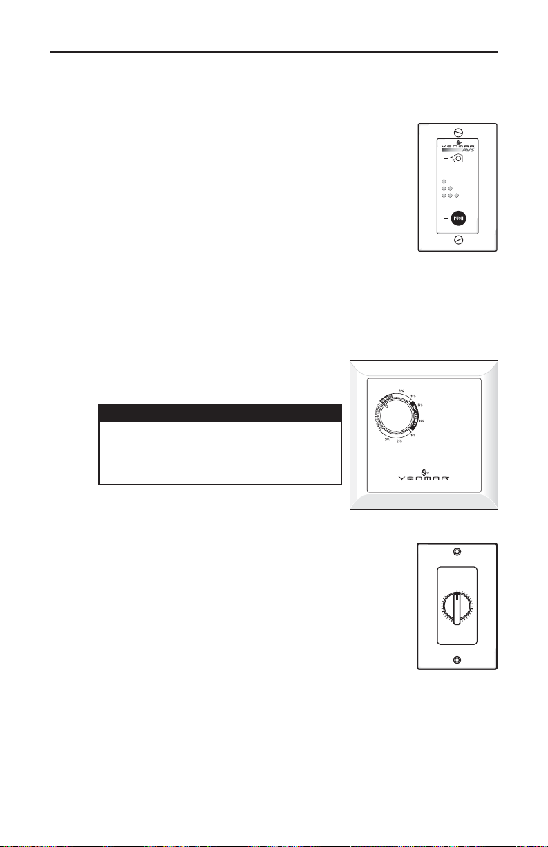
Location: Located in the bathroom or in other locations where
there is temporary humidity excess or pollutants.
Purpose: To eliminate excess humidity produced by showers
or other periodic activities producing pollutants.
Within 2 seconds, push once for 20 minutes, twice for 40 minutes
Results expected:
1. Motor speed: high for 20, 40 or 60 minutes.
2. Indicator light goes “ON” and flashes every 5 seconds (once
3.Air exchange indicator light goes “ON”.
NOTE: To stop activation, push one more time.
2.7.3 DEHUMIDISTAT (FOR HRV CONSTRUCTO 1.5V UNIT ONLY)
Adjust knob to the desired maximum indoor
humidity level.
or three times for a 60-minute activation.
VC0007
to indicate a 20-minute operation, twice for a 40-minute, and three times for a
60-minute operation).
CAUTION
Do not select a humidity level below
30%. This could lead to excessive
dryness in the air causing discomfort
for the occupants.
20 min.
40 min.
60 min.
VC0009
2.7.4 60-MINUTE CRANK TIMER (ALL UNITS)
This control makes the system operate at high speed for periods
varying from 10 to 60 minutes.
17
VC0017
OFF
Turn
Past
HOLD
10
60
20
50
30
40
MINUTES
Page 18
3. MAINTENANCE
!
WARNING
Risk of electric shock. Before performing any maintenance or servicing,
always disconnect the unit from its power source. When cleaning the unit,
it is recommended to wear safety glasses and gloves.
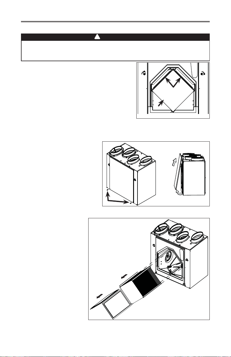
Refer to illustration at right to identify the inner parts of
your unit.
3.1 SEMI-ANNUAL MAINTENANCE
1. Turn the unit off and unplug the unit.
A
2. Remove the unit door by
following these steps:
A Remove both door lower
mechanical screws 8-32 x 1” (1)
and set aside.
B Open (2) and lift out the
door (3).
1
VO0149
3. Slide out both filters (3)
and the core (4) from the
unit.
4. Clean the inside walls of
the unit with a damp
cloth, then wipe with a
clean dry one.
5. Wash both core filters
under hot water with mild
soap. Rinse thoroughly
and let dry completely
before reinstalling on the
core.
6. Remove the dust on
the core using a vacuum
cleaner and a soft brush
attachment.
3
VD0208
4
2
1
VD0210
1) HRV or ERV core 2) Core filters
B
3
2
18
Page 19
3. MAINTENANCE (CONT’D)
3.1 SEMI-ANNUAL MAINTENANCE (CONT’D)
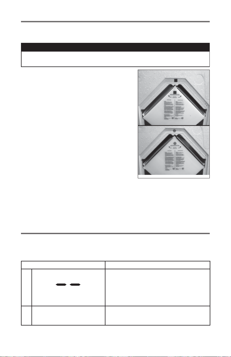
CAUTION
Make sure to align proper symbol on the core (circle or square) with
the one on the unit.
8. Slide the cleaned core into the unit.
9. Slide the cleaned filters into the unit.
NOTE: The mesh side of filters must be on
bottom (rests on core surface).
VD0209
10. Reinstall the door. Secure it with both mechanical screws 8-32 x 1” previously removed,
plug back the unit and turn it on.
NOTE: The unit will return to its previous setting after a 30-second delay for booting
sequence.
3.2 ANNUAL MAINTENANCE
Do the same operations as the Semi-Annual Maintenance (Section 3.1). Then, clean the
exterior hoods.
4. TROUBLESHOOTING
If the unit does not work properly, reset the unit by unplugging it for one minute and
then replug it. If it still not working properly, refer to table below.
PROBLEMS TRY THIS
1. On Altitude wall control, there is
no outside temperature displayed
on screen .
2. On Altitude or Deco-Touch wall
control, error code E1 or E3
appears on screen.
• At its very start-up or after a power failure, it
takes some minutes before the outside
temperature value appears on screen. Set the
wall control on MIN or MAX in VENT mode.
• If the problem is not solved by the above,
contact your installer.
• Contact your installer.
19
Page 20
4. TROUBLESHOOTING (CONT’D)
PROBLEMS TRY THIS
3. Nothing works. • See if the unit is plugged in.
• See if the unit is receiving power from the
house circuit breaker or fuse.
4. Condensation on windows
(air too humid).
5. Inside air too dry. • Temporarily use a humidifier.
6. Air too cold at the air supply
grille.
7. The LED of the integrated control
is blinking RED.
8. The LED of the integrated control
is blinking GREEN.
9. The LED of the integrated control
is blinking AMBER.
10. The integrated control push
button does not work.
• See Controls Section on pages 4 to 17.
• Leave curtains half-open to allow air circulation.
• Store all firewood in a closed room with a
dehumidifier or in a well ventilated room, or store
the wood outside.
• Do not adjust the thermostat of your heating
system below 18°C (64°F).
• See Controls Section on pages 4 to 17.
• Check if the exterior hood is not blocked.
• See Controls Section on pages 4 to 17.
• Install a duct heater.
a) HRV and ERV EKO 1.5 only: There is a problem
with one of the motors. The unit is OFF. Contact
your installer.
b) HRV Constructo 1.5V and Novofit 1.0 only:
There is a problem with the exhaust motor. The
unit is OFF. Contact your installer.
• There is a problem with the thermistor. The
unit is still working, but will defrost frequently.
Contact your installer.
• There is a problem with the motorized damper.
The unit is OFF. For a 2½-hour period, the unit
will try to reset the damper at every 30 minutes.
After 2½ hours, if the problem is not solved, the
unit stops trying to reset damper.
Contact your installer.
• The 30-second boot sequence is not completed.
See Integrated Control on page 5.
If the problem is still not solved, call your installer or the nearest approved Service Center.
Also, you can reach the Customer Service Department at the following phone number:
1-800-567-3855.
REPLACEMENT PARTS AND REPAIR
In order to ensure your ventilation unit remains in good working condition, you must use
Venmar Ventilation Inc. genuine replacement parts only. The Venmar Ventilation Inc.
genuine replacement parts are specially designed for each unit and are manufactured
to comply with all the applicable certification standards and maintain a high standard of
safety. Any third party replacement part used may cause serious damage and drastically
reduce the performance level of your unit, which will result in premature failing. Venmar
Ventilation Inc. also recommends to contact a Venmar Ventilation Inc. certified service
depot for all replacement parts and repairs.
 Loading...