

Venmar HRV NOVOFIT 1.5ES, HRV SOLO 1.5ES, HRV NOVOFIT 2.0ES, 200H, 100H User's And Installer's Manual
...Page 1

USER AND INSTALLER MANUAL
VB0253
HRV CONSTRUCTO 1.5ES
HRV CONSTRUCTO 2.0ES
HRV SOLO 1.5ES
HRV SOLO 2.0ES
HRV NOVOFIT 1.5ES
HRV NOVOFIT 2.0ES
100H
200H
NOVO+ 100H
NOVO+ 200H
1601706
1601708
1601717
1601719
46110
47110
46720
47720
46121
47121
VB0254
READ AND SAVE THESE INSTRUCTIONS
RESIDENTIAL USE ONLY
THESE PRODUCTS EARNED THE ENERGY
®
STAR
GUIDELINES SET BY N ATURAL R ESOURCES CANADA
AND THE US EPA. THEY MEET ENERGY STAR
REQUIREMENTS ONLY WHEN USED IN CANADA.
BY MEETING STRICT ENERGY EFFICIENCY
20503 REV. 10
Page 2

Please take note that this manual uses the following symbols to emphasize particular information:
⚠WARNING
Identifies an instruction which, if not followed, might cause serious personal injuries including possibility of death.
CAUTION
Denotes an instruction which, if not followed, may severely damage the unit and/or its components.
NOTE: Indicates supplementary information needed to fully complete an instruction.
LIMITATION
For residential (domestic) installation only. Installation work and electrical wiring must be done by a qualified person in accordance with all
applicable codes and standards, including fire-rated construction codes and standards.
⚠WARNING
TO REDUCE THE RISK OF FIRE, ELECTRIC SHOCK, OR INJURY TO PERSON(S) OBSERVE THE FOLLOWING:
1. Use this unit only in the manner intended by the manufacturer.
2. Before servicing or cleaning this unit, disconnect power cord from electrical outlet.
3. This unit is not designed to provide combustion and/or dilution air for fuel-burning appliances.
4. When cutting or drilling into a wall or ceiling, do not damage electrical wiring and other hidden utilities.
5. Do not use this unit with any solid-state speed control device other than those specified in section 7.2.
6. This unit must be grounded. The power supply cord has a 3-prong grounding plug for your personal safety. It must be plugged into a
mating 3-prong grounding receptacle, grounded in accordance with the national electrical code and local codes and ordinances. Do
not remove the ground prong. Do not use an extension cord.
7. Do not install in a cooking area or connect directly to any appliances.
8. Do not use to exhaust hazardous or explosive materials and vapors.
9. When performing installation, servicing or cleaning this unit, it is recommended to wear safety glasses and gloves.
10. When applicable local regulation comprises more restrictive installation and/or certification requirements, the aforementioned
requirements prevail on those of this document and the installer agrees to conform to these at his own expenses
11. Due to the weight of the unit, two installers are recommended to perform installation
CAUTION
1. To avoid prematurely clogged filters, turn the unit OFF during construction or renovation.
2. Please read specification label on product for further information and requirements.
3. Be sure to duct air outside – Do not intake/exhaust air into spaces within walls or ceiling or into attics, crawl spaces, or garage. Do not
attempt to recover the exhaust air from a dryer or a range hood.
4. Intended for residential installation only in accordance with the requirements of NFPA 90B (for a unit installed in U.S.A.) or Part 9 of
the National Building Code of Canada (for a unit installed in Canada).
5. Do not run any air ducts directly above or within 2 ft (0.61 m) of a furnace or its supply plenum, boiler, or other heat producing
appliance. If a duct has to be connected to the furnace return plenum, it must be connected 10’ (3.1 m) away from plenum’s connection
to the furnace.
6. The ductwork is intended to be installed in compliance with all applicable local and national codes.
7. When leaving the house for a long period of time (more than two weeks), a responsible person should regularly check if the unit
operates adequately.
8. If the ductwork passes through an unconditioned space (e.g.: attic), the unit must operate continuously except when performing
maintenance and/or repair. Also, the ambient temperature of the house should never drop below 18°C (65°F).
9. At least once a year, the unit mechanical and electronic parts should be inspected by qualified service personnel.
10. Do not use your unit during construction or renovation of your house or when sanding drywall. Certain types of dust and vapors may
damage your system.
11. Make sure at all times that the outside intake and exhaust hoods are free from any snow during the winter season. It is important to
check your unit during a big snow storm, so it doesn’t draw in any snow. If this is the case, please turn the unit OFF for a few hours.
12. Since the electronic control system of the unit uses a microprocessor, it may not operate correctly because of external noise or very
short power failure. If this happens, unplug the unit and wait approximately 10 seconds. Then, plug the unit in again.
2
Page 3
TABLE OF CONTENTS
FOR THE USER .......................................4
1. USING THIS UNIT ...................................... 4
1.1 Your ventilation system ...........................................4
1.2 Integrated Control...................................................4
2. USER SERVICING INSTRUCTIONS ..........5
2.1 Quarterly Maintenance ..........................................5
2.2 Annual Maintenance ..............................................5
3. USER’S TROUBLESHOOTING .................. 5
4. WARRANTY ................................................ 6
FOR THE INSTALLER ..............................4
5. AIR DISTRIBUTION .................................... 7
6. INSTALLATION ........................................... 7
6.1 Preparing the unit ..................................................7
6.2 Locating the Unit ...................................................7
6.3 Installing the Ductwork and the registers ...............8
6.3.1 Fully Ducted System ................................................. 8
6.3.2 Exhaust Ducted System - Supply Side ..................... 8
6.3.3 Exhaust Ducted System - Return Side ..................... 8
6.3.4 Simplified Installation - Return/Supply ..................... 9
6.3.5 Simplified Installation - Return/Return...................... 9
6.4 Installing the Exterior Hoods ................................9
6.5 Connecting the ducts to the Unit ......................... 10
6.6 Connecting the Drain ........................................... 11
7. CONTROLS ............................................... 11
7.1 Setting Extended Defrost ..................................... 11
7.2 Electrical Connection to Optional Wall Control .....12
7.2.1 Altitude or Platinum ................................................. 13
7.2.2 Deco-Touch ............................................................. 13
7.2.3 Lite-Touch Constructo, Simple-Touch Constructo
or Lite-Touch Bronze ....................................................... 13
7.2.4 Constructo or Bronze .............................................. 13
7.2.5 Optional Auxiliary Controls ...................................... 13
9. BALANCING THE UNIT ............................ 14
10. SERVICE PARTS .................................... 14
11. WIRING DIAGRAM .................................. 16
12. TROUBLESHOOTING ............................. 17
PRODUCT REGISTRATION CARD - FICHE D’ENREGISTREMENT DU PRODUIT
IMPORTANT:
mandatory. Your answers will be used for market research studies and reports, and will help us to better serve you in the future. IMPORTANT:
et nous le retourner dans les 10 jours suivant votre achat à l’adresse inscrite en bas de la page. Veuillez noter que seules les questions de ce côté-ci de la page sont obligatoires.
Vos réponses serviront à des études de marché et nous aideront à mieux vous servir dans l’avenir.
First name - Prénom Last name – Nom de famille
Address – Adresse Apt. no. – App. City – Ville Province Postal code – Code postal
Country – Pays E-mail address – Courriel Language preferred – Langue de correspondance
Telephone (day) – N
Model no. – No de modèle Serial – No de série
Centre d’enregistrement de produit - Product registration center, 550 boulevard Lemire, Drummondville, Québec Canada J2C 7W9
Please complete and return this questionnaire within 10 days of your purchase to the address below. Note that only the questions on this side of the page are
o
no.
--
de téléphone (jour)
Telephone (evening) – N
no.
--
no.
o
de téléphone (soir)
3
Veuillez remplir ce questionnaire
Date of purchase – Date d’achat
//
BACK / VERSO
Page 4
For the User
1. USING THIS UNIT
CAUTION
Before using this unit for the first time, please take the time to carefully read page 2 of this guide to ensure it is
used safely and properly.
1.1 YOUR VENTILATION SYSTEM
This unit is designed to provide fresh air to your home while exhausting stale, humid air. By eliminating accumulated pollutants and
humidity, it maintains an optimum air quality and an ideal relative humidity. It is equipped with a recovery core that is designed specifically
to control excess humidity and reduce ventilation costs by recovering the heat or energy from the exhausted air, and using that same heat
or energy to warm the fresh air being supplied. This recovery process is accomplished in such a way that the stale air is never mixed with
the fresh air.
When the outdoor temperature is below -5°C (23°F), recovery creates frost in the module. To maintain proper operation, the unit is
programed to defrost the recovery module. The defrost duration and frequency vary according to the outdoor temperature. After defrosting,
the unit returns to the operating mode selected by the user.
1.2 INTEGRATED CONTROL
Unit Booting Sequence
The unit’s booting sequence is similar to a personal computer’s booting sequence. Each time the unit is plugged in after being unplugged,
or after a power failure, it will perform a 30-second booting sequence before starting to operate. No command will be taken until the
unit is fully booted.
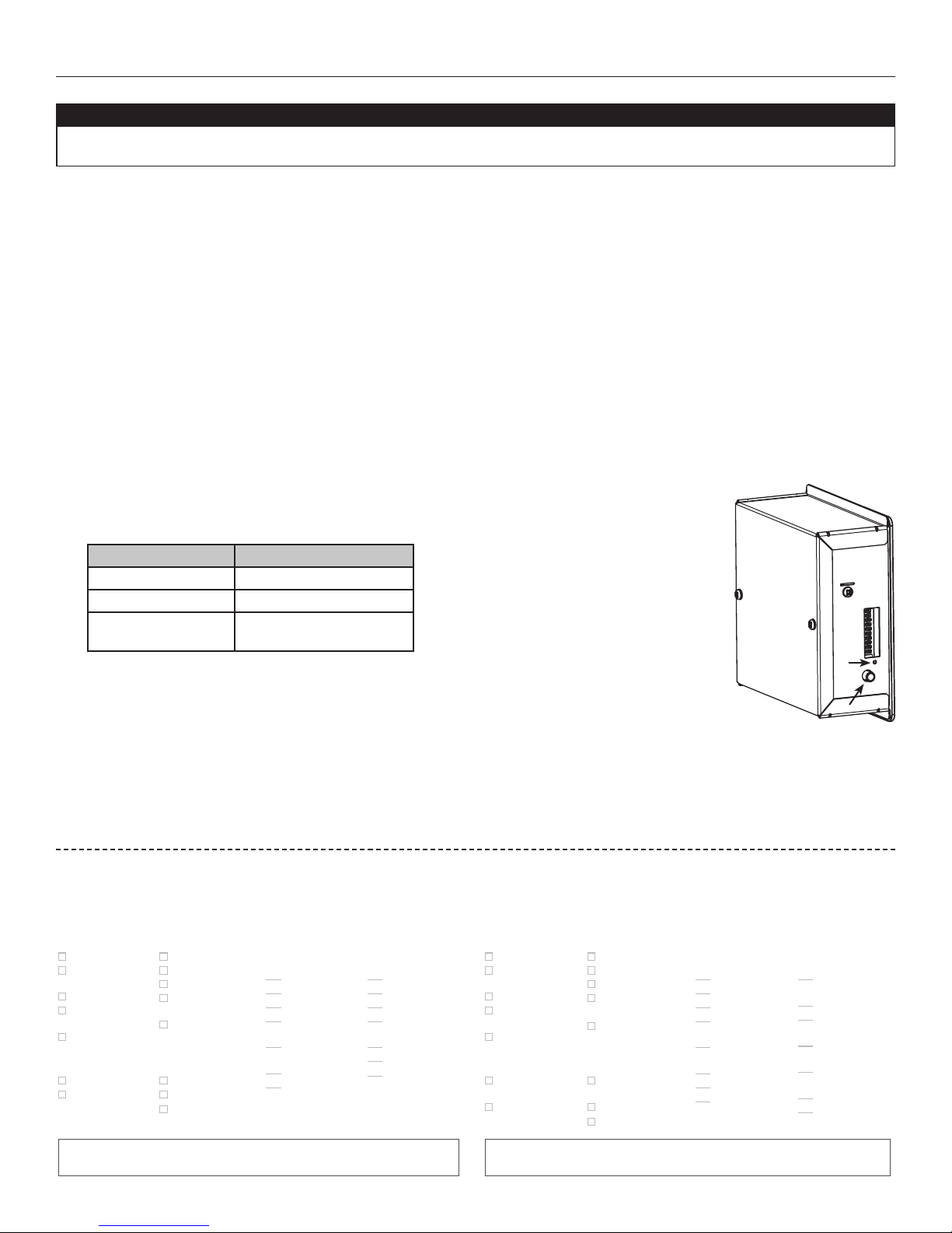
This unit is equipped with an integrated control, located on its electrical compartment.
• Use the integrated push-button to go from OFF to Low Speed, to High Speed, and back to OFF.
• The color of the LED indicator shows what speed the unit is running in:
LED COLOR RESULTS
AMBER Unit is in Low speed
GREEN Unit is in High speed
NO LIGHT
Unit is OFF or controlled
by a main control
For more convenience, this unit can also be controlled using an optional wall control. When using an optional
main control, unit must be set to OFF using the integrated control.
For more information about their operation modes refer to the Main and auxiliary wall control User Guide,
included with the ventilation unit and also available at www.vanee.ca or www.venmar.ca.
Would you like to receive occasional informational e-mail off ers including
product updates and special promotions from us?
What problem were you trying to solve with
your purchase? (Check each one that applies
to you.)
Bad odors
Respiratory
problems
Excess of humidity
Temperature
standardization
Lack of fresh air
Who installed your unit?
Home builder
Recommended
installer
Dust
Mildew
Allergies
No specifi c
problems
Others
Friend / family
Contractor
Yourself
Yes/No
Please read the following list of criteria
carefully. Indicate the importance of your
purchase decision on a scale of 1 (less
important) to 5 (most important).
Price
Warranty
Product design
Ventilation
capacity
Filter maintenance
indicator
Filtration quality
Recirculation
Heat recovery
Controls
Ease of cleaning
Manufacturer’s
reputation
Ease of use
Noise level
Other
Aimeriez-vous recevoir plus de détails sur nos promotions, off res de rabais et mises à jour
de nos produits?
Quels problèmes essayez-vous de résoudre
par cet achat? (Cochez toutes les cases
pertinentes)
Mauvaises odeurs
Problèmes
respiratoires
Excès d’humidité
Uniformisation
de la température
Manque d’air frais
Qui a installé l’appareil?
Constructeur
de la maison
Installateur
recommandé
Oui/Non
Poussières
Moisissures
Allergies
Pas de problèmes
spécifi ques
Autres (Précisez SVP)
Ami/membre
de la famille
Entrepreneur
Vous-même
Veuillez lire la liste des critères de sélection
ci-dessous. Sur une échelle de 1 (étant le moins
important) à 5 (étant le plus important), veuillez indiquer l’importance de chacun d’entre
eux dans votre décision d’achat.
Prix
Garantie
Design du produit
Débit de
ventilation
Indicateur
d’entretien du fi ltre
Qualité de fi ltration
Recirculation
Récupération
de chaleur
VD0278
2
1
Récupération
d’énergie
Fonctions
Facilité de
nettoyage
Réputation
du fabricant
Simplicité
d’utilisation
Niveau de bruit
Autres
(Précisez SVP)
Are you connected? Please do not hesitate to complete the product registration
card via our Web site at www.bnv.ca
Enregistrez-vous en ligne! N’hésitez pas à remplir la fi che d’enregistrement
du produit sur notre site Internet au www.bnv.ca
4
Page 5
For the User
2. USER SERVICING INSTRUCTIONS
2.1 QUARTERLY MAINTENANCE
⚠WARNING
• Risk of electric shock. Before performing any maintenance or servicing, always disconnect the unit from its
power source.
• When cleaning the unit, it is recommended to wear safety glasses and gloves.
1. Unplug unit.
2. Unlatch the door. Lift the panel towards you. Hold it firmly and hit on the right side of
the panel. The door will slide to the left.
3. Clean the inside of the door with a damp cloth.
4. Clean filters:
• Remove filters.
• Vacuum to remove most of the dust.
• Wash with a mixture of warm water and mild soap. You may add bleach if you wish to
disinfect (one tablespoon per gallon). Rinse thoroughly. Shake filters to remove excess
water and let dry.
5. Clean the condensation tray with a damp cloth.
6. Check the exterior air intake hood:
• Make sure there are no leaves, twigs, ice or snow that could be drawn into the vent.
• Clean if necessary.
CAUTION
Even a partial blocking of this air vent could cause the unit to malfunction.
7. Reassemble the components.
8. Reconnect power supply.
VO0229
2.2 ANNUAL MAINTENANCE
1. Perform Quarterly Maintenance up to step 6.
2. Blean the core as follows:
• Remove the core.
• Let it soak in a mixture of cold or lukewarm water and mild soap (dishwashing liquid).
• Rinse thoroughly.
• Shake the core to remove excess water and let it dry.
3. Clean blower assembly using a vacuum cleaner with a soft brush attachment to remove the dust.
4. Reassemble the components.
5. Reconnect power supply.
3. USER’S TROUBLESHOOTING
PROBLEM YOU SHOULD TRY THIS
Nothing works. • See if the unit is plugged in and receiving power from the house circuit breaker or fuse.
Noisy unit. • Clean the unit (see Section 2). If the problem is not solved, contact your installer.
Condensation on
windows (air too
humid).
Air too dry. • Operate the unit at low speed (MIN.).
Air too cold at the
air supply grille.
• Operate the unit at maximum speed (MAX.) during activities generating excess humidity (family gatherings, extra
cooking, etc.).
• Leave curtains half-open to allow air circulation.
• Store all firewood in a closed room with a dehumidifier or in a well ventilated room, or store the wood outdors.
• Keep the temperature in your house above 18°C (64°F).
• Temporarily use a humidifier.
• Temporarily switch to the intermittent mode (if available).
• Make sure the outdoor hoods are not blocked.
• Operate the unit at low speed (MIN.).
• Have the system’s balancing checked.
• Have the unit’s defrost system checked.
• Install a duct heater.
Contact customer service at 1-800-567-3855 for any unresolved issue.
5
Page 6

For the User
4. WARRANTY
This ventilation unit is a high-quality product, built and packaged with care. The manufacturer warrants to the original purchaser of its
product, that such products will be free from defects for the period stated below, from the date of original purchase. For all units, the
warranty covers parts only against any operational defect. This 5-year warranty is subject to performance of the core maintenance
according to the recommendations in this manual. The heat recovery core (HRV) has a limited lifetime warranty. If any defect should occur,
we urge you to read the user guide carefully. If the problem persists, observe the following rules:
RULES TO FOLLOW
If the unit is defective, contact your ventilation contractor (see address on your manual’s cover page). The contractor will determine with
you the reason for the defect, and if needed, do the replacement or repair. If ever it is impossible to reach your ventilation contractor, call
1-800-567-3855 (North America); the personnel will be pleased to give you the phone number of a distributor or service center near you.
REPLACEMENT PARTS AND REPAIR
In order to ensure your ventilation unit remains in good working condition, you must use the manufacturer’s genuine replacement parts only.
The manufacturer’s genuine replacement parts are specially designed for each unit and are manufactured to comply with all the applicable
certification standards and maintain a high standard of safety. Any third party replacement part used may cause serious damage and
drastically reduce the performance level of your unit, which will result in premature failing. The manufacturer also recommends that you
contact a service depot certified by the manufacturer for all replacement parts and repair.
BILL OF PURCHASE
No replacement or repair covered by the warranty will be carried out unless the unit is accompanied by a copy of the original bill of
purchase. Please retain your original.
MISCELLANEOUS COSTS
In each case, the labor costs for the removal of a defective part and/or installation of a compliant part will not be covered by the manufacturer.
CONDITIONS AND LIMITATIONS
These units are created for residential use only and must be used in a building as defined below:
Building: All structures zoned and/or erected for the act, process or art of human or animal habitation and/or the storage or
warehousing of goods.
Residential use: Dwelling, lodging, suite: Building, or part of a building, intended to act as either the domicile to one or several people
which can include general sanitary, food consumption and rest facilities. Buildings of only one room or a group of
rooms including those occupied by a tenant or owner; comprise the lodgings, the individual rooms of the motels,
hotels, rooming/lodging houses, boarding/half-way/foster homes, dormitories, and suites, as well as the stores and the
business establishments constituted by only one room in a dwelling.
Commercial use: Agricultural establishment, commercial establishment for assembly, care, or detention: Building or part of a building that
does not contain a dwelling, situated on land dedicated to agriculture or farming and used primarily to shelter animals,
or for the production, the storage or the treatment of agricultural or horticultural products or animal food. Building or
part of a building, used for the display or retail of goods, professional or personal services, or commodities. Building,
or part of a building used by persons gathering for civic activities, religious or political assembly, tourism, educational/
vocational training, recreation or the consumption of food or drink. Building, or part of a building used to shelter persons
of impaired physical or psychological states, persons requiring palliative care or medical treatments, or persons for
reasons out of their control, cannot escape harm or threat of danger autonomously.
Industrial use: Building, or part of a building, used for the assembly, the manufacture, the creation, the treatment, the repair or the
storage of products and combustible materials and that contain fuels that when ignited or exploded in sufficient quantity
may constitute a risk of fire.
The above warranty applies to all cases where the damage is not a result of poor installation, improper use, mistreatment or negligence,
acts of God, or any other circumstances beyond the control of the manufacturer. Furthermore, the manufacturer will not be held responsible
for any bodily injury or damage to personal property or real estate, whether caused directly or indirectly by the unit. This warranty
supersedes all prior warranties.
6
Page 7

For the Installer
CAUTION
• Before installing this unit, please take the time to carefully read page 2 of this guide to ensure it is installed
safely and properly.
• For Novoclimat compliant installation requirements, please refer to the current Novoclimat Program criterias.
5. AIR DISTRIBUTION
NORMAL OPERATION DEFROST MODE
VF0053
6. INSTALLATION
6.1 PREPARING THE UNIT
⚠WARNING
When performing installation, servicing or cleaning the unit, it is recommended to wear safety glasses and gloves.
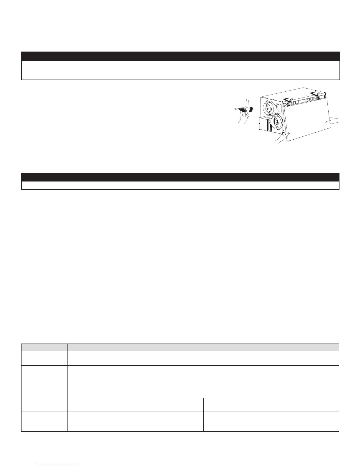
Inspect the exterior of the unit for shipping damage. Make sure that there is no damage to the door,
ports, power cord, etc.
Before installing the unit, remove the shipping bracket by unscrewing its wing nut and loosening both
retaining screws.
WING NUT
SHIPPING BRACKET
RETAINING SCREWS
VD0283
6.2 LOCATING THE UNIT
CAUTION
HRV Solo 1.5ES and HRV Solo 2.0ES units can be installed in normal or reverse postion (upside down). When
installed in reverse position in a cold region where outdoor temperature could drop below -20C (-4F) for more
than 5 days in a row, these units must always be set in extended defrost. See Section 7.1 Setting Extended Defrost.
Choose an appropriate location for the unit:
• Within an area of the house where the ambient temperature is kept between 10°C (50°F) and 40°C
(104°F)
• Away from living areas (dining room, living room, bedroom), if possible
• So as to provide easy access to the interior cabinet for quarterly and annual maintenance, and to the
control panel on the side of the unit
• Close to an exterior wall, so as to limit the length of the insulated flexible duct to and from the unit
• Close to a drain. If no drain is close by, use a pail to collect run-off
• Away from hot chimneys, electrical panel and other fire hazards
• Allow for a power source (standard outlet)
Hang the unit with the 4 chains and springs provided (see illustrations at right).
VD0037
VD0279
7
Page 8

For the Installer
6.3 INSTALLING THE DUCTWORK AND THE REGISTERS
⚠WARNING
• Never install a stale air exhaust register in a closed room where a combustion device operates, such as a gas
furnace, a gas water heater or a fireplace.
• When performing duct connections, always use approved tools and materials. Respect all corresponding laws
and safety regulations. Please refer to your local building code.
6.3.1 FULLY DUCTED SYSTEM
Stale air exhaust ductwork:
• Install registers in areas where contaminants are produced: Kitchen, bathrooms,
laundry room, etc.
• Install registers on an interior wall, 6 to 12 inches (152 to 305 mm) away from the
ceiling OR install them in the ceiling.
• Install the kitchen register at least 4 feet (1.2 m) away from the range.
Fresh air distribution ductwork:
• Install registers in bedrooms, dining room, living room and basement.
• Install registers either in the ceiling or high on the walls with the airflow directed
towards the ceiling.
• If a register must be installed in the floor, direct the air flow up the wall.
6.3.2 EXHAUST DUCTED SYSTEM - SUPPLY SIDE
CAUTION
When performing duct connections to the furnace supply
duct, use metal ducts appropriately sized to support the
additional airflow produced by the unit.
Stale air exhaust ductwork:
• Install registers in areas where contaminants are produced: Kitchen, bathrooms,
laundry room, etc.
• Install registers on an interior wall, 6 to 12 inches (152 to 305 mm) away from the
ceiling OR install them in the ceiling.
• Install the kitchen register at least 4 feet (1.2 m) away from the range.
Fresh air distribution ductwork:
• Cut an opening into the furnace supply duct at least 18 inches (0.5 m) away from
the furnace.
• Connect this opening to the fresh air distribution port of the unit (use metal ducts,
see illustration at right).
• Make sure that the duct forms an elbow inside the furnace ductwork.
NOTE : For this type of installation, it is recommended, however, not essential, that the
furnace blower be synchronized with the unit.
6.3.3 EXHAUST DUCTED SYSTEM - RETURN SIDE
Stale air exhaust ductwork:
• Install registers in areas where contaminants are produced: Kitchen, bathrooms,
laundry room, etc.
• Install registers on an interior wall, 6 to 12 inches (152 to 305 mm) away from the
ceiling OR install them in the ceiling.
• Install the kitchen register at least 4 feet (1.2 m) away from the range.
Fresh air distribution ductwork:
• Cut an opening into the furnace return duct not less than 10 feet (3.1 m) away
from the furnace (A+B).
• Connect this opening to the fresh air distribution port of the unit (see illustration
at right).
NOTE : For this type of installation, it is recommended, however, not essential, that the
furnace blower be synchronized with the unit.
VH0077
VH0130
VH0131
18” (0.5 M)
MINIMUM
A
B
A + B = AT LEAST
10’ (3.1 M)
8
Page 9

For the Installer
6.3.4 SIMPLIFIED INSTALLATION - RETURN/SUPPLY
CAUTION
When performing duct connections to the furnace supply
duct, use metal ducts appropriately sized to support the
additional airflow produced by the unit.
Stale air exhaust ductwork:
• Cut an opening into the furnace return duct not less than 10 feet (3.1 m) (A + B)
away from the furnace.
• Connect this opening to the stale air intake port of the unit (as shown above).
Fresh air distribution ductwork:
• Cut an opening into the furnace supply duct at least 18 inches (0.5 m) away from
the furnace.
• Connect this opening to the fresh air distribution port of the unit (use metal ducts,
see illustration at right).
• Make sure that the duct forms an elbow inside the furnace ductwork.
NOTE : For this type of installation, it is recommended, however, not essential, that the
furnace blower be synchronized with the unit.
6.3.5 SIMPLIFIED INSTALLATION - RETURN/RETURN
Stale air exhaust ductwork:
CAUTION
For this type of installation, the furnace must always be
synchronized with the unit. See section 7.
VH0132
18” (0.5 M)
MINIMUM
B
A
A + B = AT LEAST
10’ (3.1 M)
• Cut an opening into the furnace return duct not less than 10 feet (3.1 m) (A + B)
away from the furnace.
• Connect this opening to the stale air intake port of the unit.
Fresh air distribution ductwork:
• Cut an opening into the furnace supply duct at least 18 inches (0.5 m) away from
the furnace.
• Connect this opening to the fresh air distribution port of the unit (use metal ducts,
see illustration at right).
• Make sure that the duct forms an elbow inside the furnace ductwork.
• Make sure that both connections to the furnace return duct are at least 3 feet (1
m) apart (C).
6.4 INSTALLING THE EXTERIOR HOODS
Refer to illustration at right to connect the insulated duct to the hoods. An “Anti-Gust
Intake Hood” should be installed in regions where a lot of snow is expected to fall.
⚠WARNING
Make sure that both hoods are at least 18 inches above the
ground and that the intake hood is at least 6 feet (1.8m)
away from any of the following:
• Exhaust hood
• Dryer exhaust, high efficiency furnace vent, central
vacuum vent
• Gas meter exhaust, gas barbecue-grill
• Any exhaust from a combustion source
• Garbage bin and any other source of contamination
VH0133
EXHAUST
OOD
H
18”
(457 MM)
6’
M)
(1.8
TAPE AND DUCT TIE
CAULKING
INTAKE
H
OOD
(152
(457
18”
6” ø
MM)
T LEAST
A
3’ (1 M)
MM)
PTIONAL
O
DUCT
B
A
A + B = AT LEAST
10’ (3.1 M)
(1.8 M)
LOCATION
6’
18”
(457 MM)
VD0028
9
Page 10

For the Installer
6.5 CONNECTING THE DUCTS TO THE UNIT
CAUTION
• If ducts have to go through an unconditioned space (e.g.: attic), always use insulated ducts.
• Make sure the vapor barrier on the insulated ducts does not tear during installation to avoid condensation
within the ducts.
• Do not use screws to connect rigid ducts to the ports.
Insulated flexible ducts
Use the following procedure to connect the insulated flexible ducts to the cold side ports (stale air to outdoors and fresh air from outdoors).
1. Pull back the insulation to expose the flexible duct and place the flexible duct over inner port ring.
2. Install good quality aluminum duct tape on the flexible duct to prevent water leakage.
3. Attach the flexible duct to the port using a tie wrap.
4. Pull the insulation over the joint and tuck it between the inner and outer rings of the double collar.
5. Pull down the vapor barrier (shaded part in illustrations below) over the outer ring to cover it completely. Fasten the vapor barrier in
place using the port strap (included in parts bag). To do so, insert one collar pin through the vapor barrier and first strap hole, then
insert the other collar pin through the vapor barrier and center strap hole and close the loop by inserting the first collar pin in the last
strap hole.
12345
VJ0091
COLLAR PIN
COLLAR PIN
Rigid ducts
To prevent water leakage from ducts, use good quality aluminum duct tape to connect the rigid ducts to the ports. Do not use screws.
Make sure that both balancing dampers are left in a fully open
position before connecting the Fresh air to building port and Stale
air from building port (as shown in illustration at right).
VJ0088
10
Page 11
For the Installer
VD0308A
± 1”
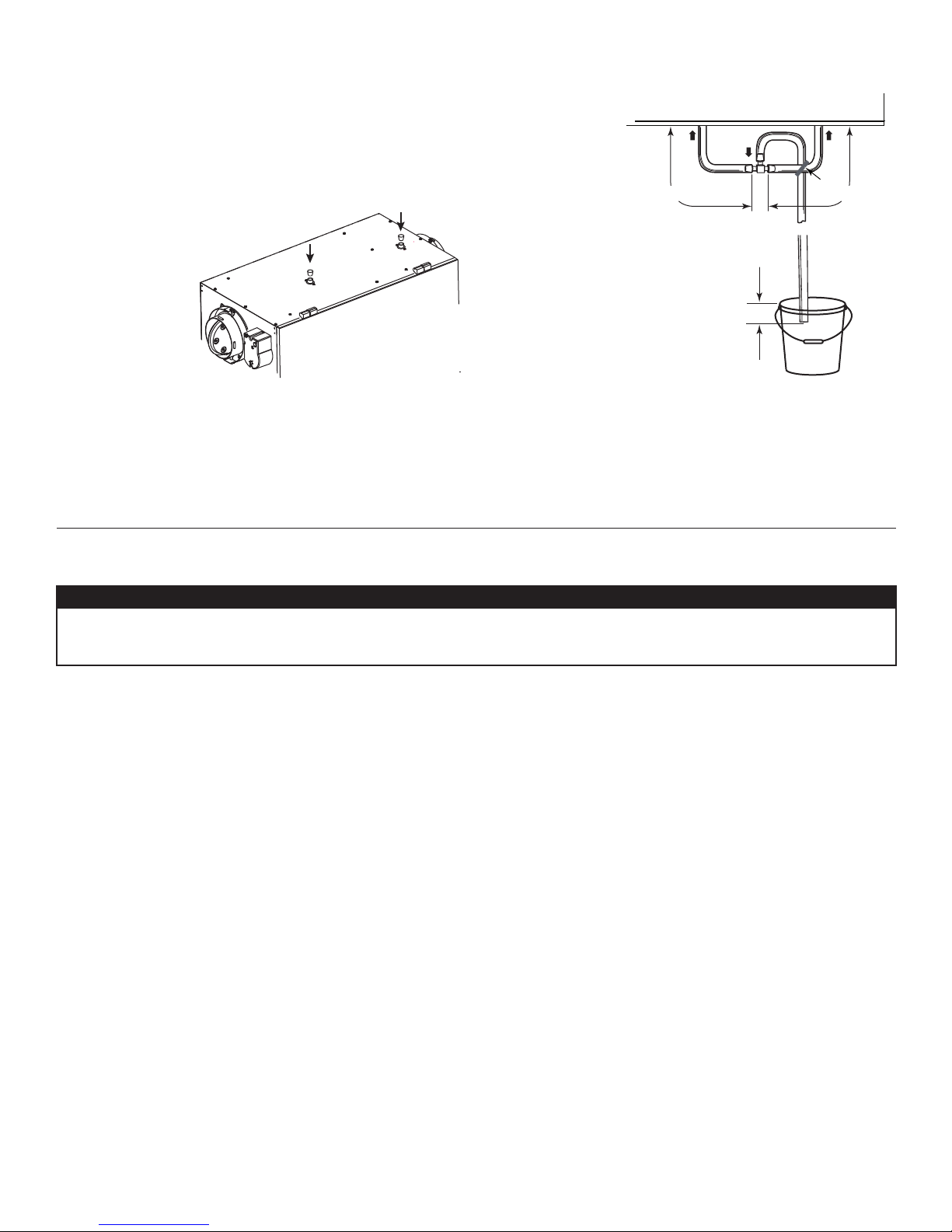
6.6 CONNECTING THE DRAIN
1. Cut 2 sections of plastic tubing of at least 12” each.
2. Connect each one of them to the inner drain fittings located under the unit.
3. Join their other ends to the "T" junction and remaining tubing as illustrated. This will
prevent the unit from drawing unpleasant odors from the drain source.
FOR HRV SOLO 1.5ES AND HRV SOLO 2.0ES UNITS ONLY:
4. Insert both drain plugs (included in parts bag) in the alternate drain fittings located on
top of the unit.
VD0282
12” minimum 12” minimum
TIE WRAP
VD0325A
7. CONTROLS
7.1 SETTING EXTENDED DEFROST
CAUTION
For HRV Solo 1.5ES and HRV SOLO2.0ES units only: when installed in reverse postion (upside down) in a cold
area where outside temperature could drop below -20C (-4F) for more than 5 days in a row, the unit must always
be set in extended defrost.
These units are factory set to normal defrost. In cold areas, it may be necessary to setup extended defrost. To do so, during the first
5seconds of the booting sequence, while the integrated control LED is GREEN, press on the integrated push button (about 3 seconds)
until the LED turns AMBER.
11
Page 12
For the Installer
7.2 ELECTRICAL CONNECTION TO OPTIONAL WALL CONTROL
⚠WARNING
Always disconnect the unit before making any connections. Failure in disconnecting power could result in electrical
shock or damage of the wall control or electronic module inside the unit.
CAUTION
Never install more than one optional main wall control per unit. Make sure that the wires do not short-circuit
between themselves or by touching any other components on the wall control. Avoid poor wiring connections. To
reduce electrical interference (noise) potential, do not run wall control wiring next to control contactors or near
light dimming circuits, electrical motors, dwelling/building power or lighting wiring, or power distribution panel.
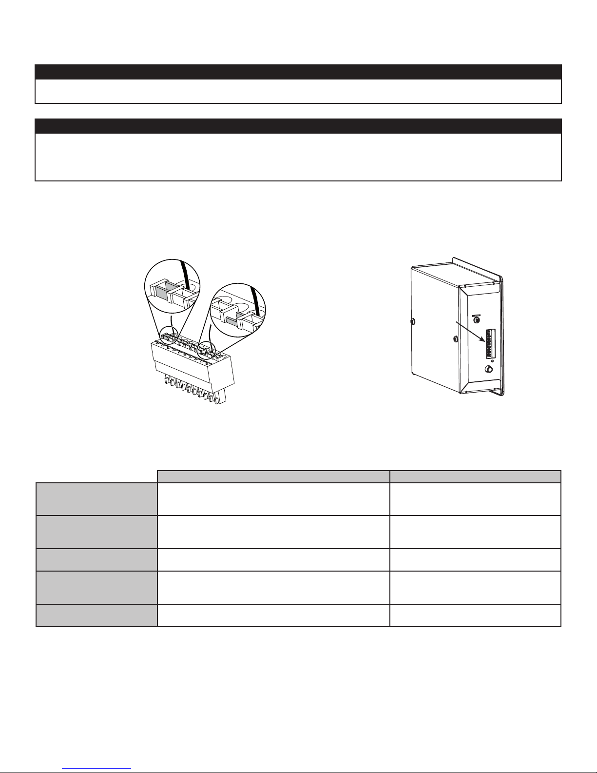
• Use the terminal connector included in the installation kit to perform the
electrical connection for main and optional wall controls.
• Make sure all wires are correctly inserted in their corresponding holes in
the terminal block. A wire is correctly inserted when its orange receptacle
is lower than another one without wire. On picture below, wire A is correctly
inserted, but wire B is not.
B
A
VE0272
• Once the wall control(s) connections have
been made, insert the terminal connector in the
electrical compartment.
• If an optional main control is being installed, make
sure that the unit is set to OFF using the integrated
push-button.
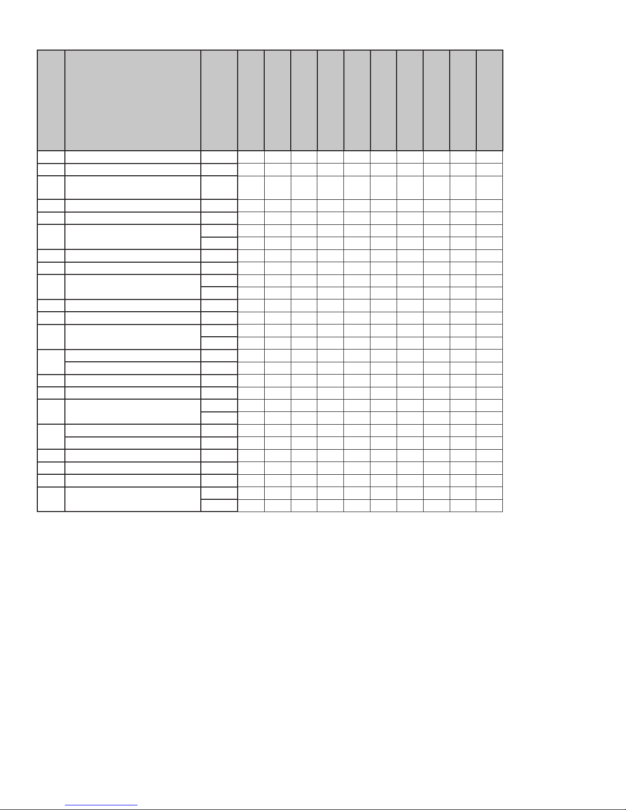
Use the chart below to verify compatibility with the optional controls before making any connection.
Main Controls Auxiliary Controls
HRV CONSTRUCTO 1.5ES
HRV CONSTRUCTO 2.0ES
HRV SOLO 1.5ES
HRV SOLO 2.0ES
HRV NOVOFIT 1.5ES
HRV NOVOFIT 2.0ES
100H
200H
NOVO+ 100H
NOVO+ 200H
• Deco-Touch
• Lite-Touch Constructo
• Constructo
• Altitude
• Deco-Touch
• Lite-Touch Constructo
• Altitude
• Deco-Touch
• Deco-Touch
• Lite-Touch Bronze
• Bronze
• Platinum
• Deco-Touch
• Simple Touch Constructo
• Constructo
• Dehumidistat
• 20-minute lighted push button
• 60-minute crank timer
• Dehumidistat
• 20/40/60-minute push-button timer
• 60-minute crank timer
• 20/40/60-minute push-button timer
• 60-minute crank timer
• Dehumidistat
• 20-minute lighted push button
• 60-minute crank timer
• 20/40/60-minute push-button timer
• 60-minute crank timer
TERMINAL
CONNECTOR
VD0278
12
Page 13

For the Installer
7.2.1 ALTITUDE OR PLATINUM 7.2.2 DECO-TOUCH
NO C NC I OC OL Y R G B
MODE
SET
PREF
SMART
VE0181
7.2.3 LITE-TOUCH CONSTRUCTO, SIMPLE-TOUCH CONSTRUCTO OR
LITE-TOUCH BRONZE
NO C NC I OC OL Y R G B
Y
BG
VE0328A
G
B
Y
7.2.5 OPTIONAL AUXILIARY CONTROLS
DEHUMIDISTAT
60-MINUTE
CRANK TIMER
20/40/60-MINUTE or 20-MINUTE
PUSH-BUTTON SWITCHES
VE0250
7.2.4 CONSTRUCTO OR BRONZE
NO C NC I OC OL Y R G B
VE0323
(5 MAXIMUM)
NO C NC I OC OL Y R G B
C
°
5
F
°
41
E
OFF
MINMAX
N
O
Z
0
T
1
X
/
R
9
X
--5°C
8
O
X
F
X
23°F
X
M
#
O
C
-20°C
-4°F
NO C NC I OC OL Y R G B
VE0089A
8. CONNECTION TO THE FURNACE
⚠WARNING
Never connect a 120-volt AC circuit to the terminals of the furnace interlock (standard wiring). Only use the low
voltage class 2 circuit of the furnace blower control.
FOR A FURNACE CONNECTED TO A COOLING SYSTE M:
On some older thermostats, energizing the “R” and “G” terminals at the furnace has the effect of energizing “Y” at the thermostat and
thereby turning on the cooling system. If you identify this type of thermostat, you must use the
STANDARD FURNACE INTERLOCK WIRING ALTERNATE FURNACE INTERLOCK WIRING
NO C NC I OC OL Y R G B
UNIT TERMINAL CONNECTOR
4 WIRES
2 WIRES
heating only
W
R
R
G
C
Y
Y
FURNACE
24-VOLT
TERMINAL BLOCK
FOUR
WIRES
TWO WIRES
heating only
W
R
G
C
Y
FURNACE
24-VOLT
TERMINAL BLOCK
VE0108A
W R G
THERMOSTAT
Y
TERMINALS
TWO WIRES
COOLING SYSTEM
ALTERNATE FURNACE INTERLOCK WIRING.
W R G Y
THERMOSTAT
TERMINAL
wiring
nuts
NO
NC
C
2 WIRES
NO C NC I OC OL Y R G B
COOLING SYSTEM
UNIT TERMINAL CONNECTOR
13
Page 14

For the Installer
9. BALANCING THE UNIT
PREPARATION
Follow these steps to ensure accurate measurements:
• Seal all the ductwork with tape. Close all windows and doors.
• Turn off all exhaust devices such as range hood, dryer and bathroom fans.
• Make sure the balancing dampers are fully open.
• If the installation is in any way connected to the ductwork of the cold air return of a furnace/air handler, make sure that the furnace/
air handler blower is ON. If not, leave furnace/air handler blower OFF.
• If the outside temperature is below 0°C/32°F, make sure the unit is not running in defrost while balancing by waiting 10 minutes after
plugging the unit in.
• Set the unit to high speed.
BALANCING PROCEDURE
1. Place the magnehelic gauge on a level surface and adjust it to zero.
2. Connect tubing from gauge to EXHAUST airflow pressure taps (see diagram on unit door).
3. Be sure to connect the tubes to their appropriate high/low fittings. If the gauge drops below
zero, reverse the tubing connections.
4. Note the CFM value from balancing chart on the unit.
5. Repeat steps 3 and 4, but to FRESH airflow pressure taps.
6. Using the appropriate adjustable balancing damper, lower the highest value so it matches
the lowest value. A difference up to ±10cfm is acceptable.
7. Secure both dampers in place with a fastening screw (included in the hardware kit).
8. Write the required airflow information on a label and stick it near the unit for future reference (date, maximum speed air flows, your
name, phone number and business address).
VP0022
10. SERVICE PARTS
3
5
6
4
7
1
19
2
18
15
17
14
8
15
16
9
VL0050
10
12
13
11
14
Page 15
For the Installer
Item Description
1 Hinge assembly kit 13036
2 Damper supply port assembly 17245
Damper system actuator
3
(incl. no. 4)
4 Thermistor kit 17242
5 Capacitor 7.5 μF 17240
6 Electronic board
7 Transformer 17244
8 Double collar port 60818
Blower assembly
9
(incl. no. 10)
10 Square damper kit 17243
11 Magnet switch 19060
Door assembly
12
(incl. hinges and latches)
Door latches (keeper) (2) 00887
13
and screws (4) 00601
14 Diffuser 60822
15 Filter kit 60800
16 Core
Door latches (2) 05960
17
and screws (4) 00601
18 Balancing damper 02253
19 Balancing double collar port 02256
* Terminal connector 16416
* Hardware kit
* Not shown.
Part
no.
17235
60809
60810
60804
60805
60797
60815
60802
60803
20510
20606
HRV Constructo 1.5ES
46110
HRV Constructo 2.0ES
47110
HRV Solo 1.5ES
46720
HRV Solo 2.0ES
47720
HRV Novofit 1.5ES
46121
HRV Novofit 2.0ES
47121
100H
1601706
200H
1601708
NOVO+ 100H
1601717
NOVO+ 200H
1601719
1111111111
1111111111
1111111111
1111111111
1111111111
111 11
1111 11
1111111111
1111111111
11111
11111
1111111111
1111111111
111111
1111
1111111111
1111111111
1111111111
1111111111
11111
111 11
1111111111
1111111111
1111111111
1111111111
1111111111
11 111111
11
Replacement parts and repairs
In order to ensure your ventilation unit remains in good working condition, you must use the manufacturer’s genuine replacement parts only.
The manufacturer’s genuine replacement parts are specially designed for each unit and are manufactured to comply with all the applicable
certification standards and maintain a high standard of safety. Any third party replacement part used may cause serious damage and
drastically reduce the performance level of your unit, which will result in premature failing. The manufacturer also recommends contacting
a certified service depot for all replacement parts and repairs.
15
Page 16

For the Installer
11. WIRING DIAGRAM
⚠WARNING
• Risk of electric shocks. Before performing any maintenance or servicing, always disconnect the unit from its power
source.
• This product is equipped with an overload protection (fuse). A blown fuse indicates an overload or a short-circuit situation.
If the fuse blows, unplug the product and check the polarity and voltage output from the outlet. Replace the fuse as per the
servicing instructions (refer to wiring diagram for proper fuse rating) and verify the product. If the replaced fuse blows, it may
be a short-circuit and the product must be discarded or returned to an authorized service center for examination and/or repair.
J10-1
Neutral
120V, 60Hz
A1
LOGIC DIAGRAM
J10-2
Line
120 V, 60Hz
NOTES
codes, ordinances and regulations.
be replaced, use the same equivalent wire.
UL listed/CSA Certified line fuse (3A, 3AG Type).
1. For continued fire protection. Use specified
2. If any of the original wire, as supplied, must
3. Field wiring must comply with applicable
4. Remote controls (class 2 circuit) available,
see instruction manual.
WIRING DIAGRAM
Critical characteristic.
J4-2
MED
COM
LOW
HI
Fan
motor
nc
J4-1
J4-3
K3
K2
321
JU1
F1
5. Furnace fan circuit must be class 2 circuit only.
J9-1
J9-2
HI
A2
J3
BK
J9-4
J9-3
LOW
DAMPER
ELECTRONIC ASSEMBLY
J1
1234512
12
J2
S1
BK
M3
Damper motor
BK
Defrost
temperature sensor
reed switch)
Door interlock switch
(magnetically actuated
T1
nc
3
2211
3
nc
C1
R1
t˚
24 V
class 2
2211
BN
BK
Motor
capacitor
Field wiring
W W
9.5 V
120 V
W
BK
class 2
Fan
motor capacitor
nc
nc
J6-2
J6-1
YRG
B
remote control
(see notes 3 & 4)
BN
BN
Y
Y
BK
R
O
W
BK
BN
ncnc
5
6
4
6
5
4
GN
BN
GND
BN
12345
3
3
O
HI
987654321
10
J8
GY
2211
GY
LO
COM
MED
J2-5
J12-5
Override
J13
J11
12
HM
213
JU1
nc
R
BL
M1
Damper motor
A2
J3-2
J2-2
J2-3
J2-4
J12-2
J12-4
J12-3
K4
J8-1
switch
notes 3 & 4)
(optional; see
ICP
12345
J12
J9
J6
BK
GN
Fan
motor
Door interlock switch
J3-1
J2-1
J11-2
J11-1
J12-1
J8-2
J8-4
J8-5
9.5 V
class 2
24 V
class 2
120 V
J14-1 : NO
Furnace blower interlock
J14
A1
ASSEMBLY
ELECTRONIC
12
1234
J10
F1
See note 1
12123
J4
nc
nc
nc
Furnace
blower
interlock
(optional; see
notes 3, 5)
J14-3
J14-1
J14-2
K5
K2K4K5
K1
K3
CPU
J14-2 : COM
J14-3 : nc
(optional; see notes 3, 5)
Line voltage factory wiring
Class 2 low voltage factory wiring
W
BK
W1
120 V, 60 Hz
Override
switch
(optional; see
notes 3, 4)
Field wiring
remote
control (see
notes 3, 4)
J14-4
J14-5
J14-6
J14-7
J14-8
J14-9
J14-10
O ORANGE
RRED
W WHITE
Y YELLOW
nc no connection
Class 2 low voltage field wiring
COLOR CODE
BK BLACK
BL BLUE
BN BROWN
GY GRAY
GN GREEN
GN
VE0257A
16
Page 17

For the Installer
12. TROUBLESHOOTING
If the integrated LED of the unit is flashing, the unit sensors detected a problem. See the table below to know more about the nature of
the problem.
LED Signal Error Type Action
LED flashes GREEN (double blink) Thermistor error Replace the thermistor kit.
LED flashes AMBER Damper error Go to page 18 "Unit does dot work".
⚠WARNING
A few diagnosis procedures may require the unit to be in operation while proceeding. Open the unit door and
bypass its magnetic switch by putting the door white magnet on it. Be careful with moving and/or live parts.
Altude or
Planum wall
con trol does not
display the outdoor
temperature
Is the unit’s
int egr ated push-
buon set to off?
Yes
Are both ends of
the control’s RED
wire properly
connected?
Yes
• Reset control:
simultaneously
press and hold
both arrow keys
for 8 seconds
• Unplug unit
• Wa it 1 m inut e
• Plug unit back
• Using the wall
control, put unit in
VENT mode at
MIN o r MAX
seng
• Wa it 5 m inut es
Is temperature now
displaying?
No
Push on the
int egr ated push-
buon unl the LED
indicator of the
int egr ated control
turns OFF
No
Restore proper
connecon
Problem solved
Yes
No
Wall control does
not work
Is the power outlet
ener gized?
Yes
Push-buon
mer does not work
(no light)
At u ni t, jump OL
and OC on the
GREEN connecto r.
Does unit now
work?
Restore conneconsYes
Yes, but
problem not
Refer to an
electrician
No
solved.
No
Th e pr oblem is not
the wall control.
Proceed to
appropria te
troubleshoong.
Change the wall
control.
No
• Unplug auxiliary controls
• Uplug unit
• Wa it 1 m inut e
• Plug unit back
• Wa it 30 seconds – Unit performs boong sequence: LED lights up, you
hear the relays, you see the dampers move
• On ce bo o ng seque nce is over (aer 30 sec . ), try opera n g t he un i t
using the integrated push-buon.
When hi ng t he int egr ate d pu sh -b uon mul pl e m es , d oes the LE D go
from OFF to A MB ER to GREEN and back to OFF?
Yes
Are the wall control
wires properly
connected? Pay
special ae non to
the BLACK and
YELLOW wires.
Use a voltmeter. Is
there 8-12 VDC
betwee n BLACK an d
YELLOW?
No
Change the wall
control
VM0008A
Change the
electr onic b oard.
Yes
Wi re o r c ontr ol is
defecve.
17
No
Test the wall control
usin g a ne w wi re .
Does the wall
control now work?
No
Yes Change the wire.
Change the wall
control.
Page 18

Unit does not wor k
Integrated control
LED is OFF
Is the power outlet
ener gized?
Yes
• Unplug auxiliary controls
• Uplug unit
• Wa it 1 min ute
• Plug unit back
• Wait 30 seconds – Uni t performs b oong sequence: LE D lights up, you
hear the r elays, you s ee the dampe rs move
• Once bo ong seque nce is over (aer 30 sec . ), try opera ng the uni t using
the integr ated push-buon .
Whe n h ing the int egr ate d pu sh -b uon mul pl e m es , d oes the LE D go
from OFF to AMBER to GREEN and back to OFF?
No
No
Refer to an
elec tric ian
Yes
Yes No
Rep lace th e
opona l wall
Is the door shut and
Integrated control
LED is AMBER and
control
magnet properly
posionned?
flashing
• Unplug auxiliary controls
• Uplug unit
• Wa it 1 min ute
• Plug unit back
• Wait 30 sec onds – Unit performs b oon g sequence: LE D
lights up, you hear the relays, you see the dampers move
Once the boong sequence is over (30 sec), does the integrated
control LED stay RED, and turn AMBER aer 7-8 m inutes?
Change the damper
system
Change the
elec troni c boar d
Yes
Yes
Change the
transformer
Shut the door and
verify that the
magnet switch is
properly placed.
No
Use a voltmeter.
Is there 24 VAC
between J8-1 and
J8-2 on the
tran sfor me r (orange
wires on the
transformer)?
No
Is the fuse on the
elec troni c boar d
blown?
No
Use a voltmeter.
Is there 120V
between J9-4 and
J9-1?
Use a voltmeter.
Is there 9.5V
between J8-4 and
J8-5?
Yes
Yes
Use a voltmeter.
Is there 120V at
J10?
Yes
NoYes
No
Call technical
support.
Replace bl own fuse
as per wiring
diagram
specifi caon s
No
Power cord is
defecve. Call
technical support.
Replace the
elec troni c boar d.
Replace the
transformer.
VM0009A
Blower does not
work
Is the jumper
present on J11?
No
Call c ustomer
service
Yes
Using a mulmeter, verify that the ohm values on
the mot or connector are as follows:
For BLUE and BLACK wires : ± 68 ohms
For BLUE and BROWN wires: ± 58 ohms
Fo r BROWN and BLACK wires : ± 126 ohms
Are all the values wh at they sh ould be?
Yes
Replace the
elec troni c board.
No
Rep lace th e moto r
Service technicians only: If you require assistance or have questions after performing the following troubleshooting, call :
HRV CONSTRUCTO 1.5ES
HRV CONSTRUCTO 2.0ES
HRV SOLO 1.5ES
HRV SOLO 2.0ES
100H 200H NOVO+ 100H NOVO+ 200H 1-888-908-2633
HRV NOVOFIT 1.5ES
HRV NOVOFIT 2.0ES
18
1-800-649-0372
 Loading...