

Venitem RIALTO L, RIALTO LSX, RIALTO LS, RIALTO X, TRIADE L User & Installation Manual
...
MA-SE-RTL0-03-01 Manuale Rialto Triade Lido Eng rev1 Page 1 of 8
INSTALLATION MANUAL
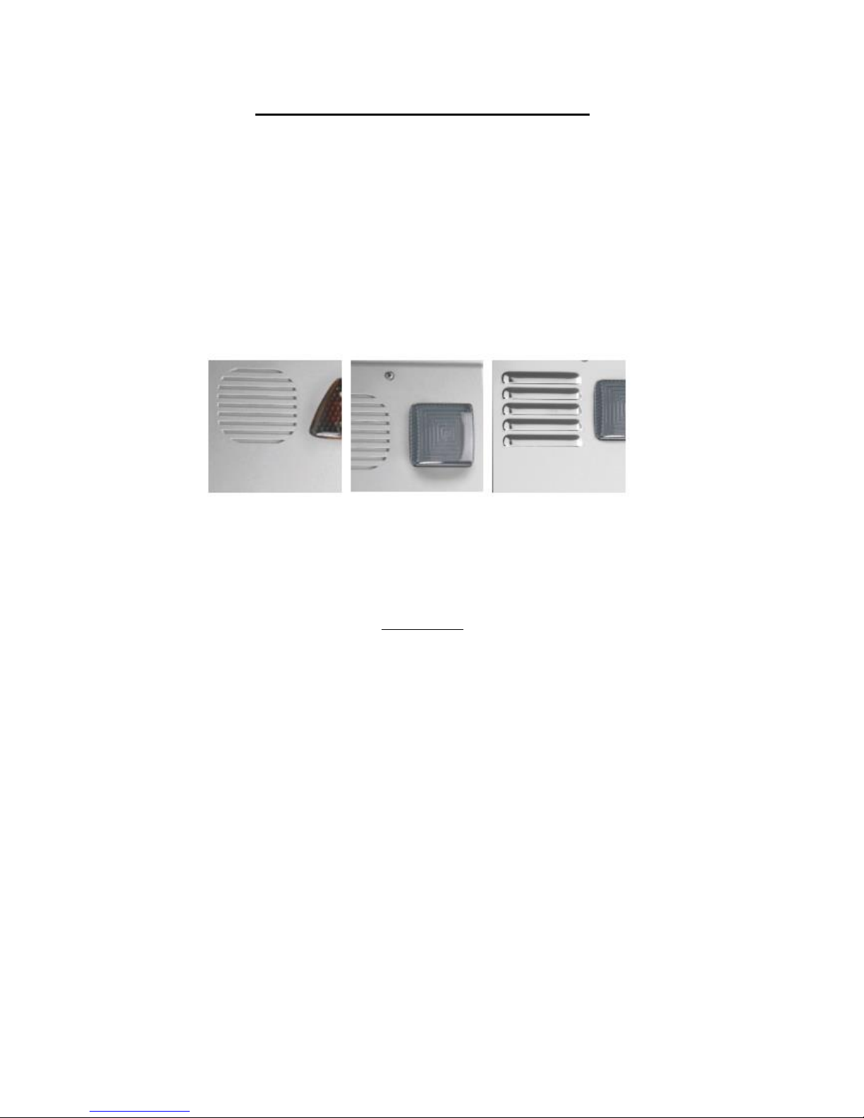
SOUNDER MODELS
RIALTO L – LS – X – LSX
TRIADE L – LS – QL – QLS
LIDO L – X – LS – LSX
DESCRIPTION
L models description: self-powered 12 Vdc sounder with high-brightness low-consumption LED flashing unit - double reed
tamper against sounder opening and against any attempts of removing the sounder from the wall – programmable sounds and
timings – alarm counting – optical and acoustic signaling of System ON/OFF (arming/disarming) - electronic circuit protected
against polarity inversion and tropicalized by resin immersion – microprocessor self-check of recharge, battery and speaker –
flash reset input – internal cover made of 10/10 zinc-plated steel (Aluzinc system) – outside cover made of painted ABS or 10/10
zinc-plated steel (Aluzinc system) or shiny stainless steel according to the model chosen.
LS models description: technical features as per L models, with patented double micro anti-foam anti-shock device against hard
hits (patent no. 00238576).
MA-SE-RTL0-03-01 Manuale Rialto Triade Lido Eng rev1 Page 2 of 8
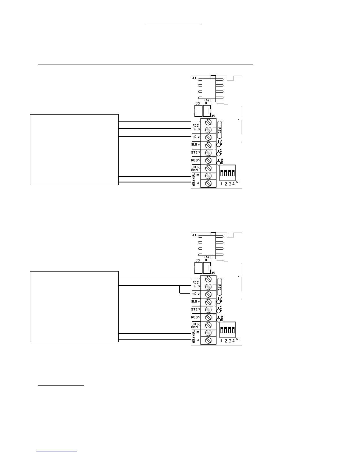
CONNECTION SCHEME
A) CONNECTION USING THREE WIRES.
Connect 13.8 Volt power supply coming from the control panel to the corresponding terminals:
-RIC negative; +RIC positive; +C positive-missing trigger.
NOTE: DIP-SWITCH no. 2 is set by the manufacturer in OFF position, POSITIVE-MISSING TRIGGER.
B) CONNECTION USING TWO WIRES
Connect 13.8 Volt power supply coming from the control panel to the corresponding terminals:
-RIC negative; +RIC positive. (make a jumper between +C and +RIC).
NOTE: DIP-SWITCH no.2 is set by the manufacturer in OFF position, POSITIVE-MISSING TRIGGER
C) BLS TERMINAL, NEGATIVE INPUT FOR SOUND BLOCK
It activates the sound interruption trigger by taking a negative (0V) to terminal no. 4.
D) STI TERMINAL, SYSTEM STATUS NOTICE (PERMANENT/MOMENTARY ALARM SYSTEM ON/OFF)
DIP 3 in OFF position
Giving a positive to terminal no. 5, all LEDs of the flashing unit flash 3 times (ON). Anomalies are reset to zero.
Taking away the positive, all LEDs stay lighted up steady for 5 seconds (OFF) and the complete sounder test is launched. In
case of anomalies, they are duly notified.
PONT 1 (R74) – UNTOUCHED (STANDARD SETTING): Momentary ON-OFF signaling and 1 LED keeps on flashing in intermittent mode
until there is positive signal to terminal no. 5.
PONT 1 (R74) – CUT: Momentary ON-OFF signaling
GND 0V
+13.8Vdc and SOUNDER TRIGGER
TAMPER LINE
CONTROL PANEL
GND 0V
+13.8V
OUTDOOR SOUNDER TRIGGER
TAMPER LINE
CONTROL PANEL
MA-SE-RTL0-03-01 Manuale Rialto Triade Lido Eng rev1 Page 3 of 8
DIP 3 in ON position
Giving a negative (0V) to terminal no. 5, all LEDs of the flashing unit flash 3 times (ON). Anomalies are reset to zero.
Taking away the negative, all LEDs stay lighted up steady for 5 seconds (OFF) and the complete sounder test is launched.
In case of anomalies, they are duly notified.
Activated sounds: To activate sounds (three BEEPs while arming and a long BEEP while disarming) set DIP 4 in ON position.
E) RES TERMINAL, NEGATIVE INPUT OF FLASHING UNIT RESET
When set (through PONT no. 2), it stops the flashing activity of the flashing unit by taking terminal no. 6 to 0V for one second.
F) OUT ANM TERMINAL AND ANOMALY LED
The sounder is managed by a microcontroller able to check if the battery recharging process is going on properly, if the battery
status is good, if the speaker is good or faulty and if the power amps are in good condition. In case of anomaly, the opencollector terminal OUT ANM opens and LD1 LED on the sounder board shows the fault type by making a certain number of
flashes followed by a short pause.
The microprocessor automatically performs the battery current test every 4 hours. Moreover, it continuously performs other
tests. If the sounder is correctly supplied, the anomaly output (terminal no. 7) usually stays at 0V (max consumption 50mA). If
any of the tests performed fails, the anomaly output disconnects from ground and becomes free.
When the sounder receives power supply for the first time (13V or battery), to make installation easier, anomalies are
automatically reset to zero when their cause disappears. After the first alarm trigger, anomalies are reset to zero only
through +C, RES or a command to STI.
To launch the remote test, take terminal no. 5 (STI) to 12V for 10 seconds, then take away the voltage from the terminal.
These steps launch the test which will last 60 seconds. During the test, the sounder verifies its own functioning and notifies
any anomalies both through the anomaly output (OUT ANM) and the anomaly LED, as indicated in the chart below. To reset
the anomaly to zero, remove its cause first, then wait 10 seconds and take terminal no. 5 (STI) to 12V for at least 10
seconds. When the command is taken away from terminal +C for a very short time lapse, all anomalies are reset to zero
with the exception of those concerning the battery. After 4 hours from battery restore, the sounder performs the tests
once again and updates the anomaly notices, including battery anomaly.
In case any anomaly appears, the flashing unit LEDs flash faster and the acoustic notice at arming becomes a single BEEP.
ANOMALY NOTICE CHART
ANOMALY red LED
ANOMALY OUTPUT (OUT NO. 7)
SPEAKER INTERRUPTION (test performed every 10 s)
1 FLASH
OUTPUT OPEN (OPEN COLLECTOR OFF)
NO RECHARGE CURRENT (recharge current is lower than 11.5V)
(test performed every 10 s)
2 FLASHES
OUTPUT OPEN (OPEN COLLECTOR OFF)
BATTERY IS DISCONNECTED, IS LOWER THAN 2.5 V
(test performed every 4 hours)
3 FLASHES
OUTPUT OPEN (OPEN COLLECTOR OFF)
BATTERY IS INSUFFICIENT, IS LOWER THAN 10 V
(test performed every 4 hours)
4 FLASHES
OUTPUT OPEN (OPEN COLLECTOR OFF)
INTERNAL BATTERY RESISTOR > 3.5 OHM
(test performed every 4 hours)
5 FLASHES
OUTPUT OPEN (OPEN COLLECTOR OFF)
SPEAKER POWER AMPs ARE INTERRUPTED
(test performed every 10 seconds)
6 FLASHES
OUTPUT OPEN (OPEN COLLECTOR OFF)
SOUNDER IS NOT POWERED OR SOUNDER MICROPROCESSOR IS
FAULTY
OFF
OUTPUT OPEN (OPEN COLLECTOR OFF)
NO ANOMALIES
OFF
OUTPUT TO GROUND, 0V
(OPEN COLLECTOR IS ACTIVE)
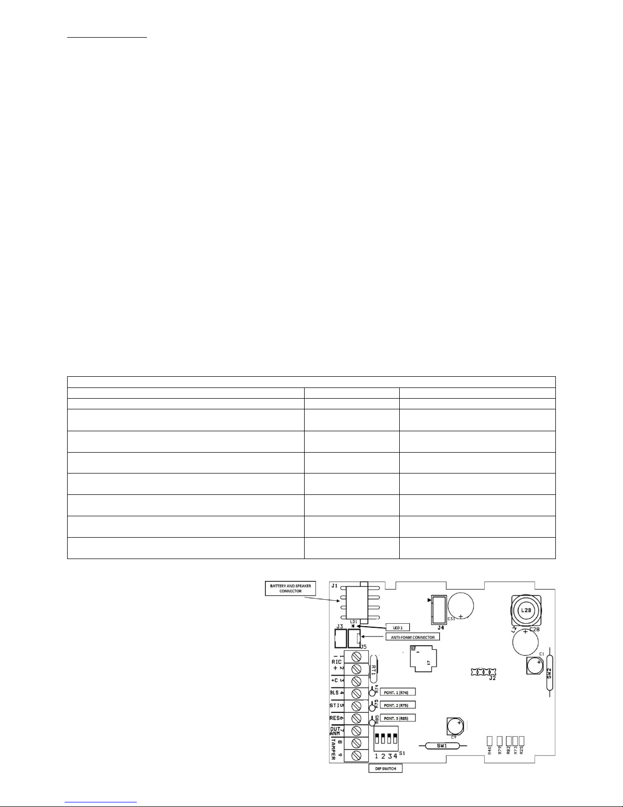
G) ANTI-OPENING AND ANTI-REMOVAL TAMPER
CONNECTION
Connect TAMPER terminals no. 8 and no. 9 to the
tamper line coming from the control panel.
H) BATTERY CONNECTION
Connect the 12V battery to the corresponding
connector faston.
 Loading...