

Venitem DOGE EV12, DOGE EV24, DOGE EV230 Installation Manual
Power supply, voltage, current
EV12V
From 10V to 15Vdc – Maximum current from +RC
700mA
EV24V
From 20V to 30Vdc – Maximum current from +RC
400mA
EV220V
230Vac +/- 10%
Current MAX speaker from
battery
1,4A (programmable – see chart)
Flashing light current
80 mA 10 mA
Fundamental frequency
See chart
Max decibel
106 dB @ 3m
LED flashing light duration
1.000.000 flashes
Water/dust protection level
IP 44
Environmental class
IV (outdoor)
Operating temperature
from –25°C to +55° C
Alarm duration
Programmable (see chart)
Activation trigger
See chart
Battery
12V 2Ah (for all models of Doge EV)
Size 330x210x115 (H x W x D)
Weight
1.980 gr
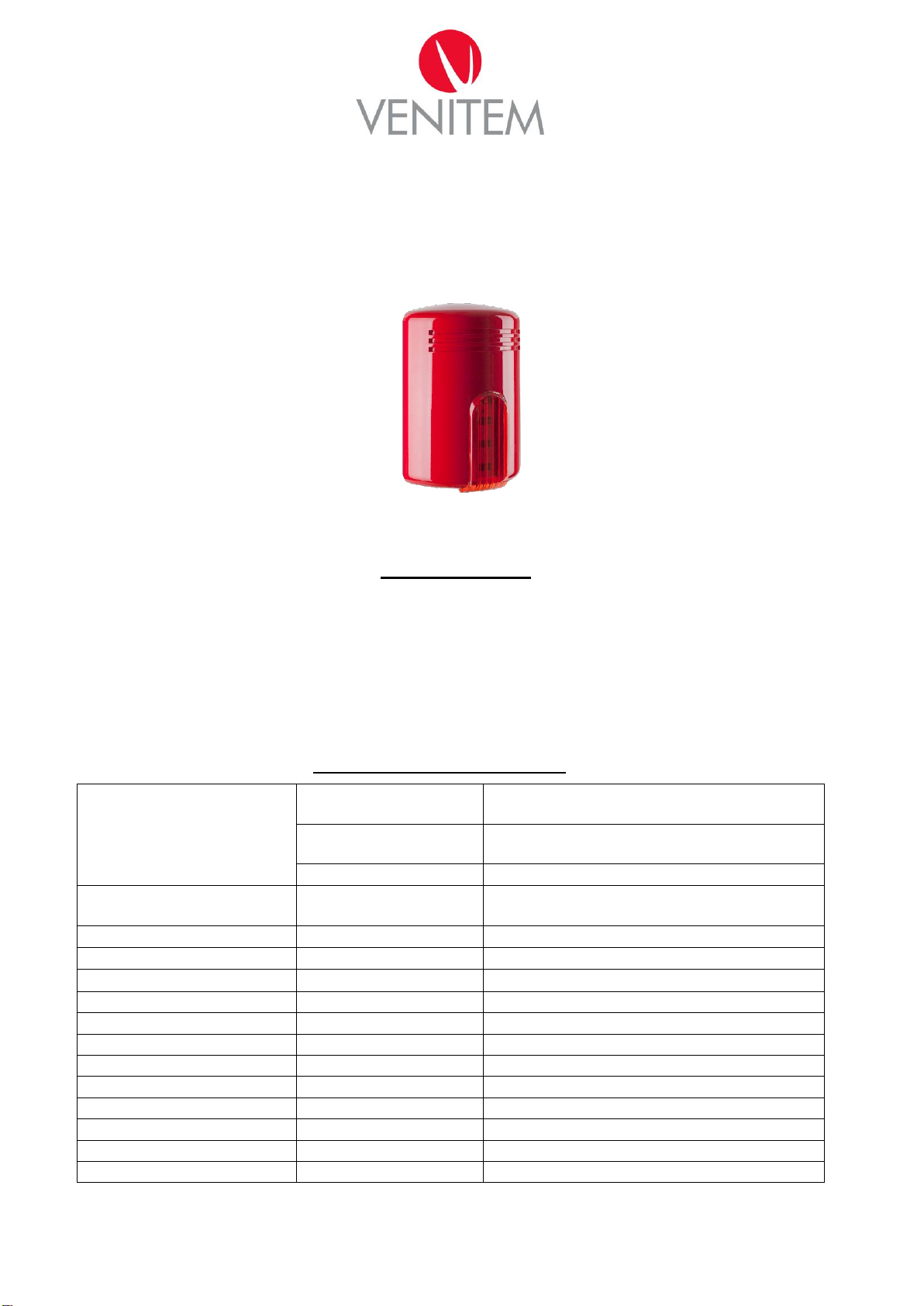
EVACUATION SOUNDER
DOGE EV12 – EV24 – EV230
INSTALLATION MANUAL
DESCRIPTION
3 input outdoor sounder with 10 sounds for evacuation alarms. Two sound power regulations.
Possibility to choose the trigger type among positive or negative missing or giving.
Connection for sound synchronism among all the sounders.
LED flashing light for anomalies signalization, for example: power supply shortage, battery fault, speaker not working.
The current consumed by the control panel or by the power supply is limited to 700mA for EV12 model and 400mA
for EV24 model.
Timed alarm sound duration.
TECHNICAL FEATURES
MA-SE-EVA1-01-00 Manuale Doge Evacuazione eng rev0 Page 1 of 4
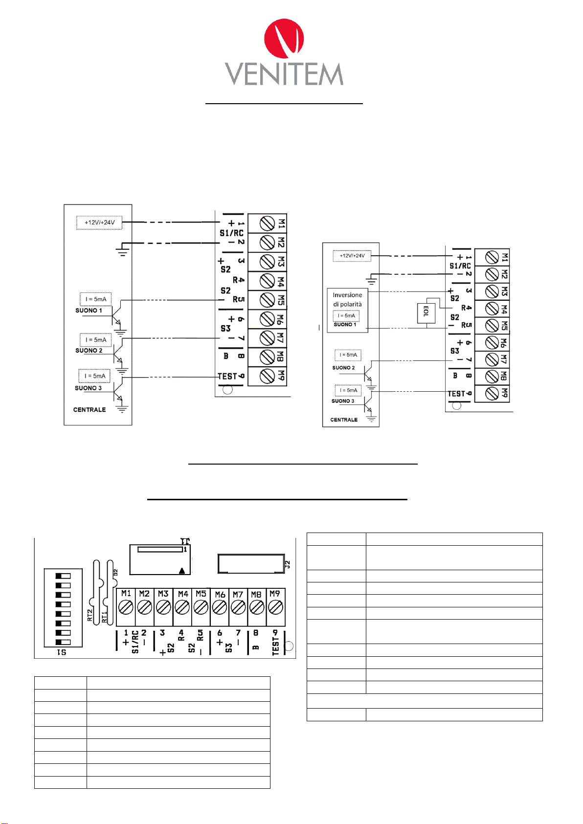
Chart 1
Terminals
Connections
+ S1/RC (1)
12V battery recharge (EV12 and EV230)
or 24V (EV24)
- S1/RC (2)
Battery recharge 0V
+S2 (3)
Relay anomaly 100mA/ 48V MAX
R (4)
Relay anomaly 100mA/ 48V MAX
-S2 R (5)
Evacuation command 1 input
+ S3 (6)
+12V positive output used to trigger the
inputs
- S3 (7)
Evacuation command 2 input
(8)
Syncronism
(9)
Evacuation command 3 input
Terminals on TL1207
0 - 230
Power supply for Doge EV230
Table 2 DIP SWITCH
DIP
Function
DIP1
Alarm timing
DIP2
Alarm timing
DIP3
System status
DIP4
Consumed power and current
DIP5
Sounds group selection
DIP6
Sounds group selection
DIP7
Trigger polarity, positive or negative
DIP8
Transition giving or missing trigger
ON
OFF
J1 Battery and
speaker
Connection
J2 LED
Connection
NEGATIVE GIVING TRIGGER 3
SOUND CONNECTION
Connect the 12Vcc or 24Vcc power supply to the
recharging terminals S1/RC (Recharge) 1 and 2.
Connect inputs 5,7,9 with DIP7 = ON and DIP8 =
ON, as shown in the picture below
NEGATIVE GIVING TRIGGER AND
POLARITY INVERSION 3 SOUNDS
CONNECTION
Connect the 12Vcc or 24Vcc power supply to the
recharging terminals S1/RC (Recharge) 1 and 2.
Connect the end line resistance coming from the fire
control panel to the terminals 4 and 5. Connect in
polarity inversion the inputs 3, 5 to the fire control
panel. Connect 7 and 9 as shown in the picture below.
DIP7 = ON and DIP 8 = ON
CONNECTION SCHEME
ATTENTION: IN CASE THE SOUNDER IS SET WITH MISSING TRIGGER AND ONE OR MORE OF THE
THREE INPUTS ARE NOT USED, CONNECT THE INPUTS THAT ARE NOT USED TO THE
NEGATIVE/POSITIVE, FOLLOWING DIP 7
TERMINALS and DIP-SWITCH SETTING
MA-SE-EVA1-01-00 Manuale Doge Evacuazione eng rev0 Page 2 of 4
 Loading...