

Venitem DOGE CT3 User Manual

Alarm Bell/Control Panel
DOGE CT3
General Features:
DOGE CT3 is a sounder having functions of control panel for burglar alarm systems with 3 detection lines + 1 24 hours line.
The control panel can be managed via mechanical key or via Vela remote control (not given within)
The housing in ABS can locate a 12V 1.2 Ah or 12 V 2.2 Ah battery.
Connector for Vela remote control.
DOGE CT3 can be interfaced via the MCX or MCV optional boards for connecting from 1 to 4 inertial/vibration contacts.
High-luminous LED flash.
Easy programming via dip-switch.
3 immediate detection lines of N.C. or balanced type (selection by dip4)
1 detection line programmable as immediate or delayed (selection by dip2)
1 24 hours auto-protection line with immediate alarm also at disarmed system. The line can be excluded for servicing interventions
with the function of “block of auto-protection” opening the cover (see the paragraph “Service and Test”)
One partialization, by remote control, which excludes the zone 3
Flash at 3 luminous areas indicating the alarm zone
4 LED on board for detailed indication of anomalies during installation and service
Programming via dip-switch
2 programmable sounding
2 temporization for adjusting the input/output timing (input: 1 min or 30 sec; output: 1 min or 2 min)
2 temporization for adjusting the alarm duration (3 or 8 min) via dip1
Painted ABS cover, charged against UV
Protection against wall-tampering and cover-opening
Protection against polarity inversion
Discharged battery causes block of the horn and quick flashing further to block of the inputs reading, included key and remote
control in order to avoid false alarms
With very low battery the external LEDs switch off and the board resets
Indication of battery-resistance status. Indication of discharged battery.
Indication of broken horn
Indication delayed mains missing by Led on board, delayed on the terminal
Alarm relay output – free exchange for max 5 A. Can be used also with MiniDoge or other indoor siren, outdoor siren or telephone
dialer (optional)
Direct push-pull output for positive driving of the MiniDoge Led at totally or partially armed system
Alarm-memory, open collector output for driving a remote Led or telephone dialer
DOGE CT3 used in combination with Vela remote control (optional) leaves free the 2 relays of the receiver in order to connect one or
two channels of the telephone dialer for the silent alarm
Detectors supplying output with tension always present even at disarmed system
Input for external mechanical key. Can be interfaced with relay electronic keys
Circuit of recharge and control of back-up battery
2 auto-restorable fuses for separate protection of: board supplying and detectors supplying
Possibility of total arming by key and total or partial arming by remote control
Indication on flash of: armed system, partial, disarmed. First zone in alarm. Anomaly
0,5 A stabilized power supply, protected against short-circuit
Possibility of walk-test with attenuation on horn
MA-SE-DCT3-01-02 Manual Doge CT3 eng rev2 Rev.4 Pagina 1 di 17
DIP5
Command
Flash status
OFF (default)
ARMED
All Leds flash 3 times and then switching off of the whole flashing
OFF (default)
PARTIAL
The central Led flash 3 times and then switching off of the whole flashing
OFF (default)
DISARMED
All Led switch on for 5 seconds and then switch off
ON
ARMED
All Led flash 3 times then flash of the central Led with 1 pulse and then pause
ON
PARTIAL
The central Led flash 3 times and then flash of the central Led with 2 pulses and
then pause
ON
DISARMED
All Led switch on for 5 seconds and then switch off
ON and OFF
ALARM
All Led flash with a pause. The number of flashes shows the zone in alarm
ON and OFF
TAMPER
All Led rotate
TOTAL ARMING: 1 FLASH AND PAUSE
PARTIAL ARMING: 2 FLAHES AND PAUSE
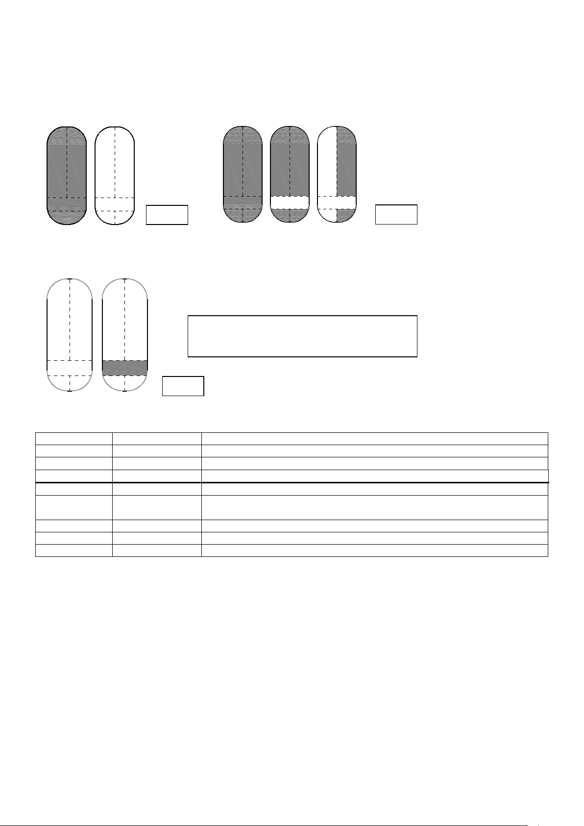
Pict. 1
Pict. 2
Pict. 3
Flashing of the front LEDs of the sounder
Pict. 1 ALARM ZONE 1, 2 e 3 Pict. 2 ALARM ZONE 24h and TAMPER
Pict.. 3 SYSTEM STATUS
(chart 1) Visualization of System Status
If the input/output time is activated, the Led, all of them or the central ones, flash until the end of the output time
If, during the input/output the zone 1 is open, the flash accelerates in order to show a pre-alarm condition
The flashing remains until the disarming of the system via the key
In case of anomaly all flashes accelerate.
MA-SE-DCT3-01-02 Manual Doge CT3 eng rev2 Rev.4 Pagina 2 di 17
LEDs INSIDE THE SOUNDER
Priority
CHART OF TAMPER AND NON-BALANCED ZONES INDICATION
Number of flashes
1
Zone1
1 FLASH
2
Zone 2
2 FLASHES
3
Zone 3
3 FLASHES
4
Zone 24h
4 FLASHES
5
Housing tamper or anti-foam
5 FLASHES
6
Anti-drilling (not given within)
6 FLASHES
0
Board awaiting change of inputs, as a consequence of reset
FIX ON
Priority
CHART OF INDICATION AND ANOMALIES
RED LED LD1
1
Speaker interruption
1 FLASH
2
Mains missing with immediate indication (tension of the supply unit less than
11,9V)
2 FLASHES
3
Battery not connected
3 FLASHES
4
Battery spoilt – Inside resistance higher than 2,5 Ohm
4 FLASHES
5
Low battery – tension lower than 10,5V
5 FLASHES
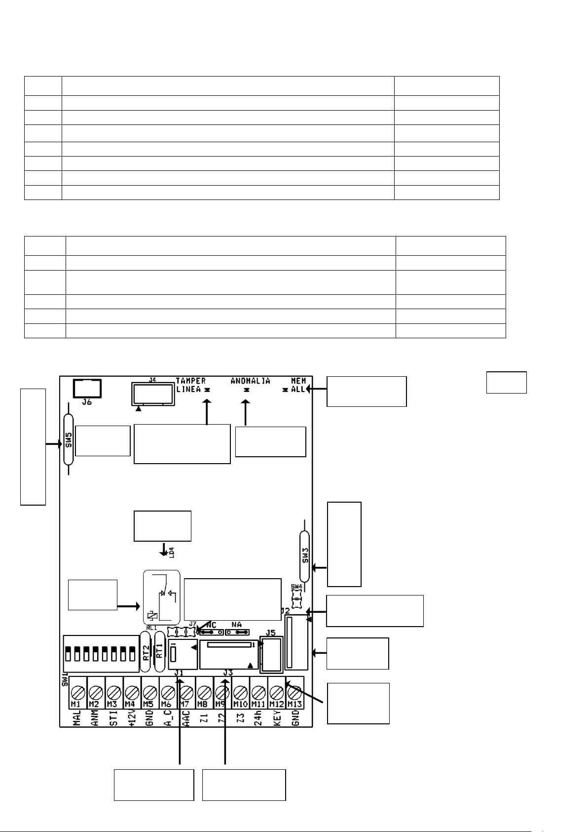
TAMPER AND
NOT-BALANCED
ZONES LED
ANOMALIES
LED
ALARM MEMORY
LED
ALARM
LED
RELAY
ALARM
1 2 3 4 5 6 7 8
SOUNDER
JUMPER TAMPER
FLASH
CONN.
.RECEIVER
VELA
CONN.
HORN AND
BATTERY CONN.
SUPPLY UNIT
CONN.
ANTI-FOAM
CONN
TAMPER
COVER
OPENING
TAMPER
REMOVAL
FROM THE WALL
Pict. 4
J7 RELAY OUTPUT
SELECTION
NC -- NO
LED 1: LINES TAMPER, see also paragraph TAMPER.
(chart 2) LED Tamper LD5
LED 2: ANOMALY OF LOCAL VISUALIZATION see also paragraph ANOMALIES
(chart 3) LED Anomalies LD1 - flashes
LED LD3: ALARM MEMORY, activated with the terminal MAL during the alarm and until the reset set by dip7
LED LD4: ALARM, activated with relay (terminals: A_C, AAC) for the alarm duration set by dip 1.
MA-SE-DCT3-01-02 Manual Doge CT3 eng rev2 Rev.4 Pagina 3 di 17

MAL
M1
Alarm memory output; on in alarm and alarm memory. Tamper output, 24 hours alarm.
Open collector, 0V = alarm
ANM
M2
Output for anomaly output and mains missing after 3 hours. Open Collector, ground =
anomaly
STI
M3
Output for system status, positive push pull = system armed
+12V
M4
Supplying , with auto-restorable fuse for detectors and devices
GND
M5
Ground
A_C
M6
Dry-contacts alarm relay, Common
AAC
M7
Dry-contacts alarm relay, NC or NO contact, selection via jumper
Z1
M8
Zone 1 – Connect to ground (or with terminal resistance) if not used
Z2
M9
Zone 2 – Connect to ground (or with terminal resistance) if not used
Z3
M10
Zone 3 – Connect to ground (or with terminal resistance) if not used
24h
M11
24h line – Connect to ground if not used
KEY
M12
Key of total arming: Free = total arming, 0V = off.
GND
M13
ground
CONNECTIONS:
TERMINALS (chart 4):
+MAL Open collector output for alarm memory. Activated to 0V in case of alarm, tamper alarm and alarm for balanced line in
short-circuit. Active until cancellation of the alarm memory as set by dip7. Can be used for Led switching-on, relay or to activate a
telephone dialer.
ANM Anomaly open collector output, 0V in case of anomaly – see chart 3. Activated after 3 hours of missing mains. Can be
used for Led switching on, relay or activation f a telephone dialer.
STI Push-pull output for system status, 12V in case of totally armed system, intermitting in case of partially armed system, 0V
in case of disarmed system. Can be connected to the Led of system status of Minidoge or Minimurano.
+12V Output with 13 V tension always available, protected by auto-restorable fuse. Can be used for supplying detectors and
bells.
GND Ground terminal for connecting negative of all peripherals or detectors.
A_C Dry-contacts alarm relay, Common Terminal.
AAC Dry-contacts alarm relay, terminal settable as normally open or normally closed selecting the jumper J7. Active in Alarm,
Tamper Alarm and balanced-line in short-circuit for the duration set by DIP1
Z1: Zone of NC detection or single balancing, immediate or delayed. One or more series input-detectors are connected to this
zone. If set as single balancing, connect a 5600 Ohm resistance in series to the cable
Z2, Z3: Zones of NC detection or single balancing, immediate. One or more input detectors are connected in series. If set as single
balancing, connect a 5600 Ohm resistance in series to the cable
24h: NC immediate “auto-protection” detection line. All NC contacts of the auto-protection devices of the detectors, alarm
indicators and additional units if any, have to be connected to this terminal. The status variation of one device triggers off the alarm
immediately with both armed or disarmed system.
KEY: Key line. A NC-to-ground line has to be connected to this terminal. When the line is closed the system is disarmed, when it
is open the system is totally armed. Connect towards the ground when you wish to have the system re-activated in “disarmed”
mode after a long mains missing
Note: the zones and the 24 hours line, if not used, must be connected to the ground.
MA-SE-DCT3-01-02 Manual Doge CT3 eng rev2 Rev.4 Pagina 4 di 17
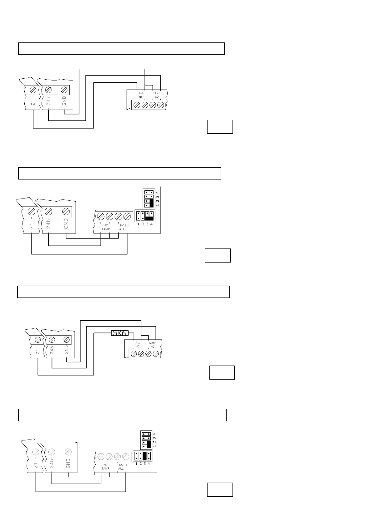
FARO DT
DOGE CT
Pict. 8 Connection with balanced line and FARO DT detector tamper
STANDARD DETEC
DOGE CT
Pict. 7 Connection balanced line and STANDARD AM detector tamper
STANDARD DETECTOR
DOGE CT
Pict. 5 Connection with NC line and tamper STANDARD detector
FARO DT
DOGE CT
Pict. 6 Connection with NC line and FARO DT detector tamper
Pict. 5
Pict. 7
Pict. 7
Pict. 8
MA-SE-DCT3-01-02 Manual Doge CT3 eng rev2 Rev.4 Pagina 5 di 17
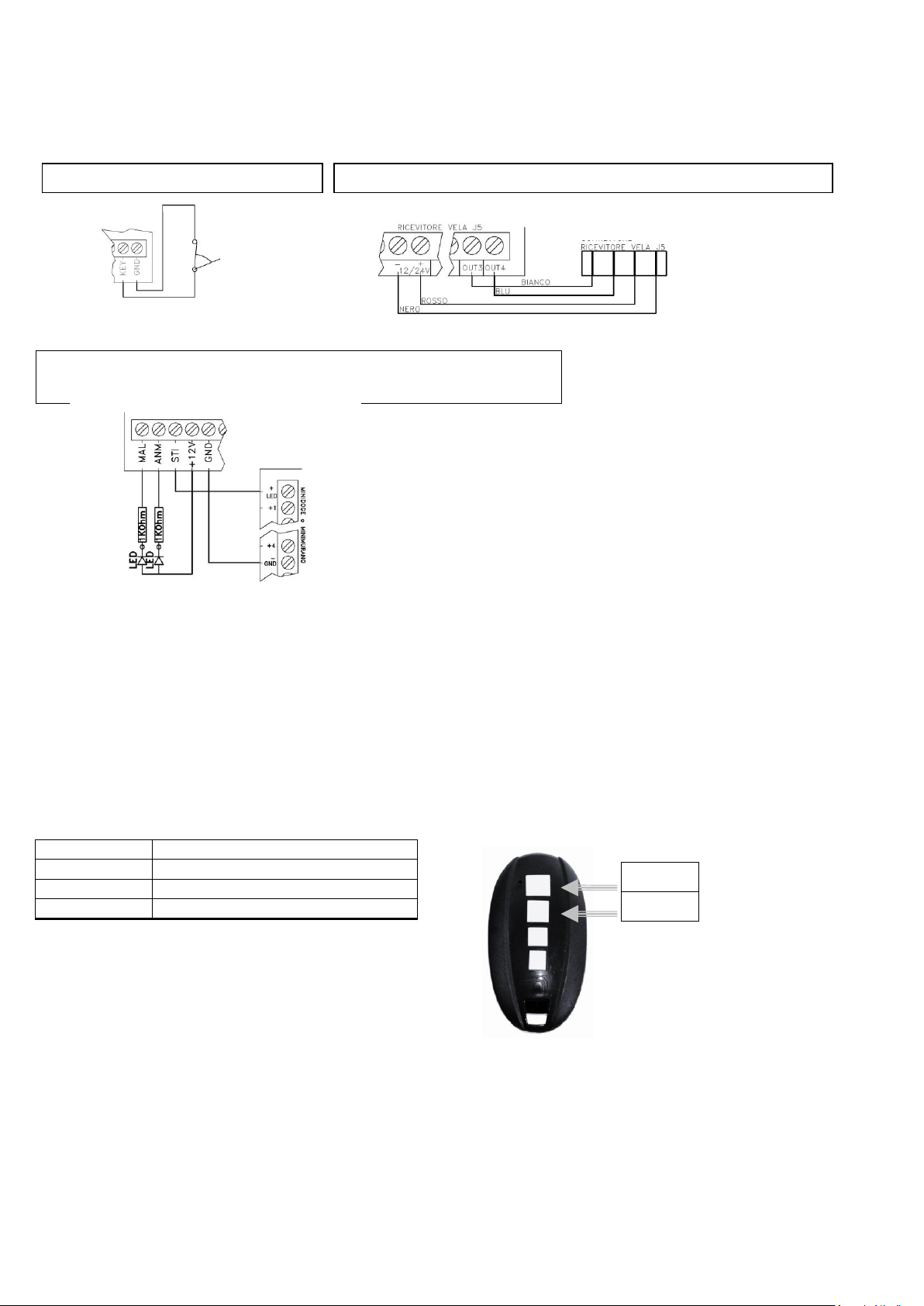
Push button
System status
A
Total arming
B
Partial arming
A and B
At armed system, it switches it off
Pict. 9 Connection with key line
Pict. 10 Connection with receiver Vela remote control
Pict. 11 Connection with Minidoge or Minimurano.
Remote LED (not given) for indicating Anomaly and Alarm
RECEIVER VELA
RECEIVER VELA
CONN. J5
Button A
Button B
Programming of the remote control (optional): the control panel accepts pulse-commands (from open line with a pulse towards
ground) on the two lines of the remote control connector. Command of total arming on line 1, commando of partial arming on line
2. A pulse of at least 1 second on any of the two lines causes the switching off of the control panel.
Connect the cables to the terminal board of the receiver -12V BLACK, +12V RED, OUT4 BLUE, OUT3 WHITE as on the picture 10.
Memorize the first pushbutton of the remote control on OUT3 and the second on OUT4 (the open collector outputs of the Vela
receiver). Program the two outputs as mono-stable.
Two pushbuttons and two relays of Vela remain free: they can be used maybe to command a silent alarm connecting the relays to
the line of a telephone dialer.
(chart 5) Remote control
MA-SE-DCT3-01-02 Manual Doge CT3 eng rev2 Rev.4 Pagina 6 di 17
 Loading...