

Page 1
INSTALLATION, MAINTENANCE AND USE
INSTRUCTIONS FOR
FREE-STANDING COOKERS
90x60 cm (type M9V)
60x60 cm (type M6V)
VEF91EG
VEF61EG
READ THE INSTRUCTION BOOKLET BEFORE INSTALLING AND USING
THE APPLIANCE.
The manufacturer will not be responsible for any damage to property or to persons
caused by incorrect installation or improper use of the appliance.
The manufacturer is not responsible for any inaccuracies, due to printing or transcription
errors, contained in this booklet. In addition, the appearance of the figures reported is also
purely indicative.
The manufacturer reserves the right to make changes to its products when considered
necessary and useful, without affecting the essential safety and operating characteristics.
Page 2

CONTENTS:
THINK APPLIANCES ..................................................................................................................................... 3
INSTALLER TECHNICAL MANUAL ............................................................................................................... 4 - 14
Installing the cooker ........................................................................................................................................ 5 – 6
Room ventilation ............................................................................................................................................. 6
Location and aeration...................................................................................................................................... 6
Appliance gas connection ............................................................................................................................... 7
Adaption to different types of gas.................................................................................................................... 7 – 10
Burner adjustment........................................................................................................................................... 10 – 11
Appliance electric connection.......................................................................................................................... 12 – 13
Important warnings.......................................................................................................................................... 13
Replacing parts............................................................................................................................................... 14
USE AND MAINTENANCE MANUAL ............................................................................................................. 15
Gas burner / hot plate dimensions .................................................................................................................. 15
Control panel description................................................................................................................................. 15
Using burners.................................................................................................................................................. 16 – 17
Use of electric plates....................................................................................................................................... 17 – 18
Using the ceramic hob .................................................................................................................................... 18
Using the gas oven ......................................................................................................................................... 18 – 20
Using the thermostat with switch in series....................................................................................................... 21
Using the electric thermostat ........................................................................................................................... 21
Using the oven function knob.......................................................................................................................... 22
Using the natural conventional electric oven................................................................................................... 23
Using the ventilated electric oven.................................................................................................................... 23 – 24
Using the gas grill............................................................................................................................................ 24 – 25
Using the conventional electric grill................................................................................................................. 26
Using the ventilated electric grill...................................................................................................................... 26
Using the minute minder ................................................................................................................................. 26
Analogue clock with timer................................................................................................................................ 27
Electronic timer ............................................................................................................................................... 27 – 28
Cleaning the appliance.................................................................................................................................... 28
After-sales technical service and spare parts.................................................................................................. 29
2
Page 3
3
Page 4

THIS APPLIANCE HAS BEEN DESIGNED FOR NON-PROFESSIONAL DOMESTIC USE
INSTALLER TECHNICAL MANUAL
This appliance conforms with the regulations of European directive 2002/95/CE.
This appliance is marked according to the European directive 2002/96/EC on Waste Electrical and
Electronic Equipment (WEEE).
This guideline is the frame of a European-wide validity of return and recycling on Waste Electrical
and Electronic Equipment.
This symbol on the product, or on the documents accompanying the product, indicates tha t this
appliance may not be treated as household waste. Instead it should be handed over to the applicable
collection point for recycling of electrical and electronic equipment.
Disposal must be carried out in accordance with local environmental regulations for waste disposal.
For more detailed information about treatment, recovery and recycling of this product, please
contact your local city office, your household waste disposal service or the shop where you
purchased the product.
INSTALLER INFORMATION
The installation, all adjustments, transformations and maintenance listed in this part of the manual must be
carried out only by skilled personnel.
Improper installation may cause damage to persons, animals or property, for which the manufacturer will not be
held responsible.
The appliance safety or automatic adjustment d evices may be changed during the service life of the system only
by the manufacturer or by the duly authorised supplier.
4
Page 5
INSTALLING THE COOKER
After having removed the various loose parts from the internal and external packing, make sure that the cook er is not
damaged. If in any doubt, do not use the appliance and contact skilled personnel.
Keep all the dangerous packing parts (polystyrene foam, bags, cardboard, staples, etc.) away from children.
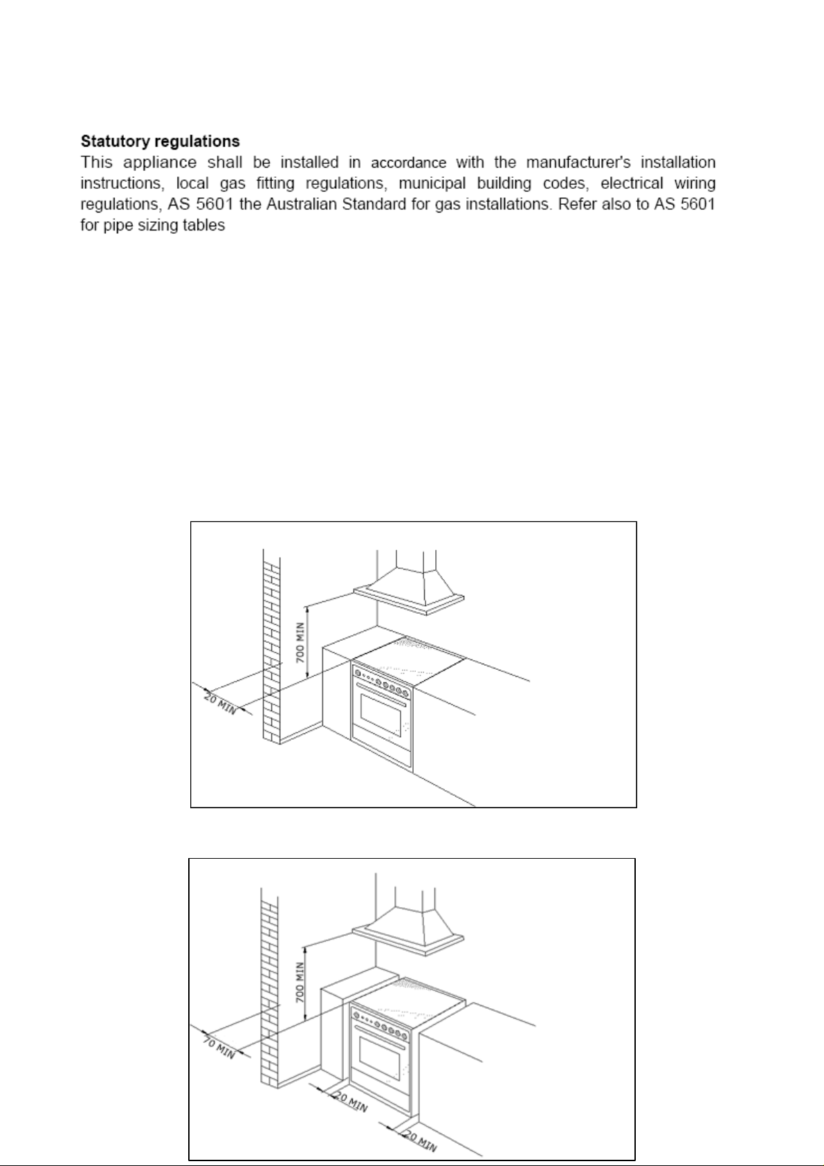
The appliance can be installed as a freestandin g unit, next to a wall at a distance of no l ess than 20mm (Fig.2,
Installation) or inserted between two walls (Fig.1, Class 2 Subclass 1 Installation). A single si dewall that exceeds the
height of the work surface is possible. This must be at a minimum dista nce of 70 mm fro m the edge of the cooker (Fig. 2,
Class 1 Installation).
Class 1
WARNING: In order to prevent accidental tipping of the app liance, for example by a child climbing on to the
oven door, the stabilizing means must be installed according to these instructions
Any walls of the adjacent furniture pieces and the wall behind the c ooker must be made of heat-resistant material that
can withstand a minimum temperature of 65°C.
Fig. 1
Fig. 2
5
Page 6

IMPORTANT INFORMATION FOR INSTALLING THE APPLIANCE
The cooker can be installed separately, as a f reestanding unit, or between kitchen units or between a kitchen
unit and the wall. The device must be installed in acc ordance with the regulations stated in UNI 7129 and UNI
7131 standards.
This appliance is not connected to devices which exhaust combustion products.
Special attention must be focused on the prescriptions described below regarding room aeration and
ventilation. Any hanging cabinets installed above the work surface must be lo cated at a distance of no less than
700 mm.
ROOM VENTILATION
To ensure that the appliance operates correctly, the room where it is installed must be continuously vent ilated. The roo m
volume should not be less than 25 m³ and the quantit y of air needed shoul d be based on the regular co mbustion of gas
and on the ventilation of the room. Natural air will flow through permanent openings in the walls of the room to be
ventilated. These openings will be connect ed with the outside environment and should have a minimum cross-secti on
defined by the current national standards regarding room ventilation (Fig. 3).
These openings should be built so that they cannot be clogged.
Indirect ventilation is also permitted by taking air from the rooms adjacent to the one to be ventilated.
Fig. 3
LOCATION AND AERATION
Gas cooking appliances must always evacuate the combus tion products by means of hoods connected to chimneys,
flues or directly outside (Fig. 4). If a hood cannot be installed, it is possible to use a fan installed on a window or directly
facing outdoors, to be operated together with the appliance (F ig. 5), provided that there is strict compliance with the
ventilation regulations.
Fig. 4 Fig. 5
6
Page 7

APPLIANCE GAS CONNECTION
Before connecting the appliance to the gas net work, make sure that the data on the label attached to the food warmer
drawer or on the back of the cooker are compatible with what is indicated for the gas distribution network.
The label in the food warmer drawer (or on the back) of the appliance indicates the appliance adjustment conditions: type
of gas and operating pressure.
IMPORTANT: This appliance must be installed in compliance with current national standards in force and
used only in a well-ventilated room.
WARNING: The appliance utilises a threaded 1/2" gas cylindrical male fitting according to UNI-ISO 228-1.
To connect the appliance to the gas network with a flexible rubber hose, a supplem ental hose nipple fitting is needed
(Fig. 6) which is supplied with the appliance.
7
Page 8
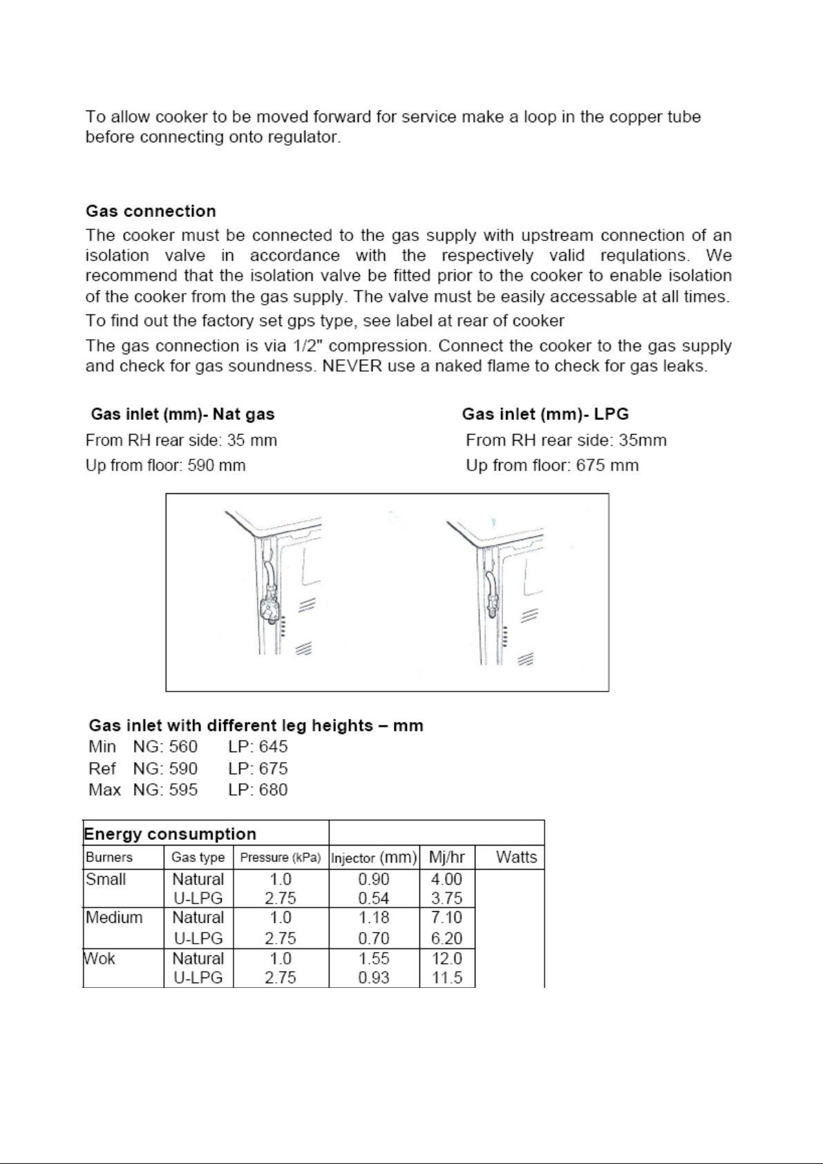
Table 1
8
Page 9
9
Page 10
10
Page 11
11
Page 12
ADAPTATION TO DIFFERENT TYPES OF GAS
Before performing any maintenance operation, disconnect the appliance from the gas supply and electricity
network.
REPLACING THE NOZZLES TO OPERATE WITH ANOTHER TYPE OF GAS
Follow the instructions below to change the burner nozzles on the work surface:
1) Pull out the plug from the electric outlet to avoid any type of electric contact.
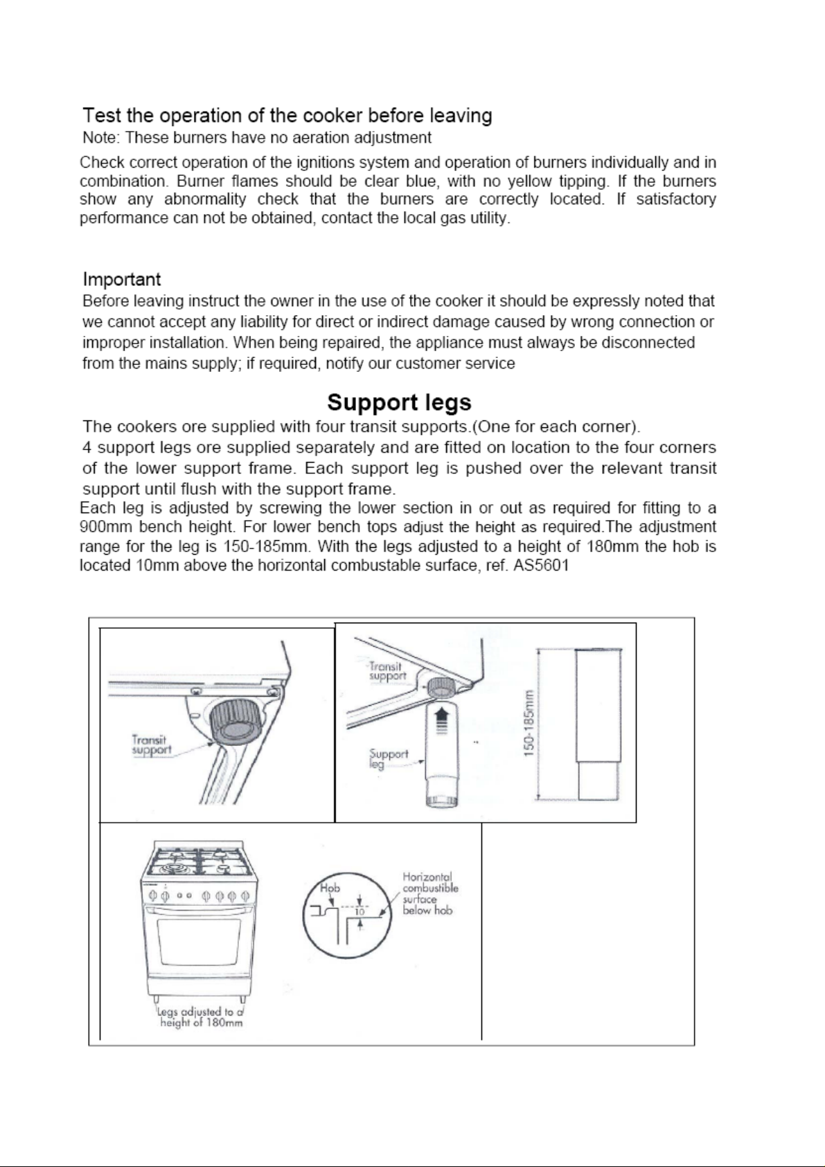
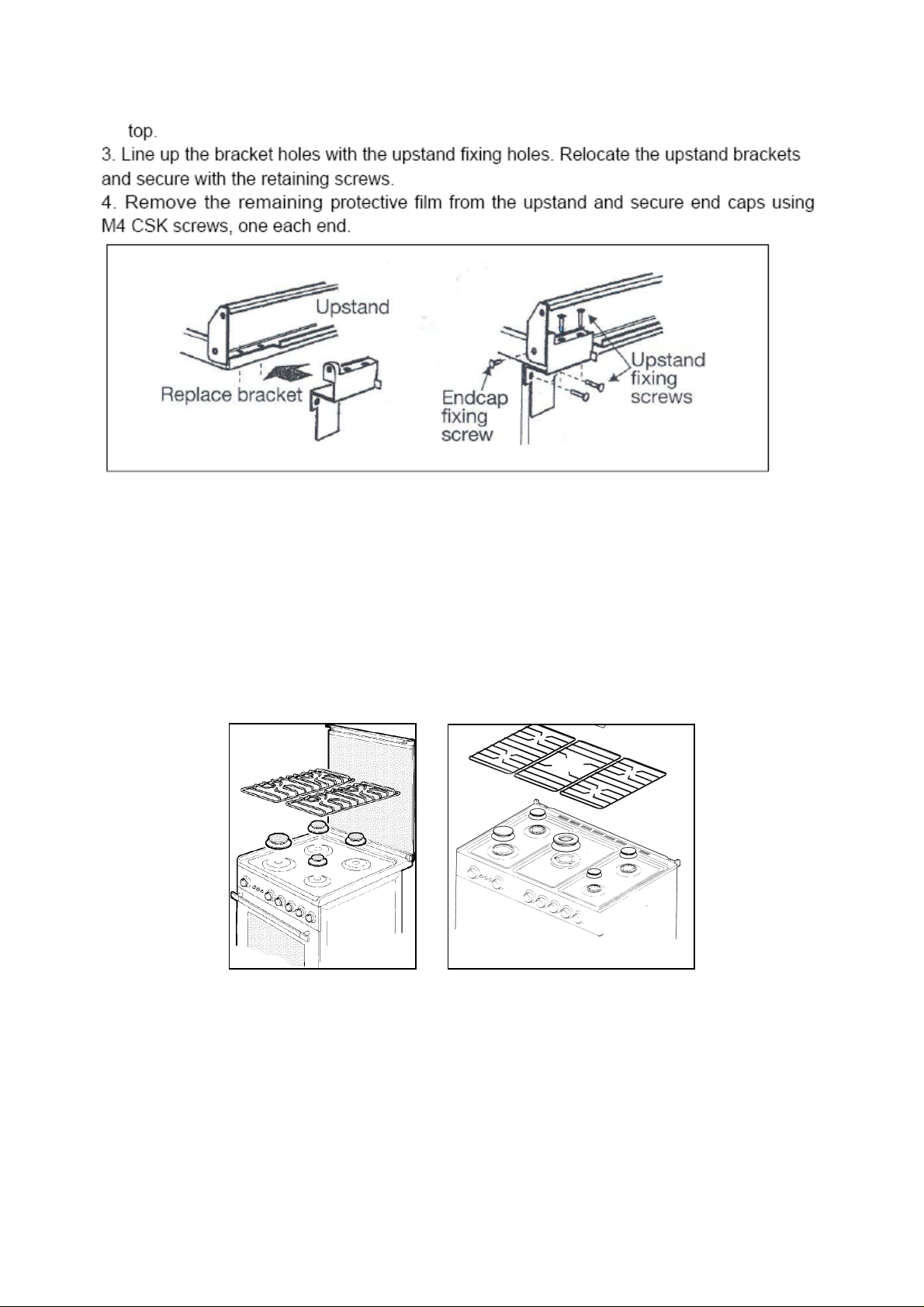
2) Remove the grids from the work surface (Fig. 7A-7B).
3) Remove the burners (Fig. 7A-7B).
Fig. 7A Fig.7B
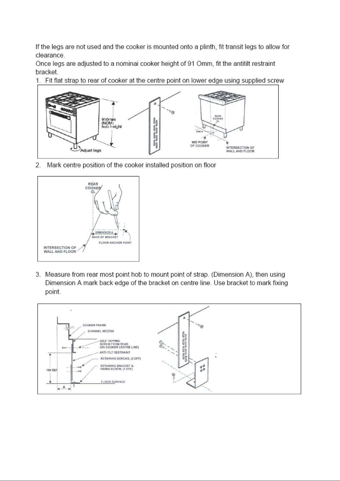
4) Unscrew the nozzles using a 7 mm spanner, and replace th em (Fig.8) with those needed for the new type of gas
according to what is indicated in Table 1 for model VEF61EG and in Table 2 for model VEF91EG.
12
Page 13
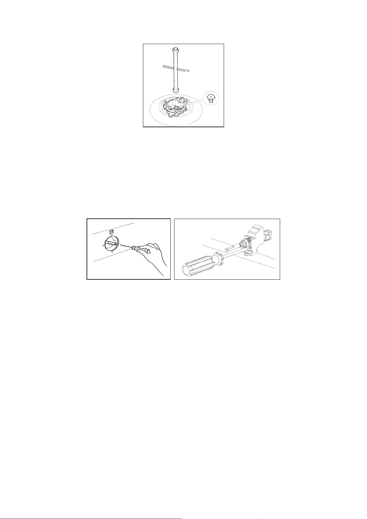
Fig. 8
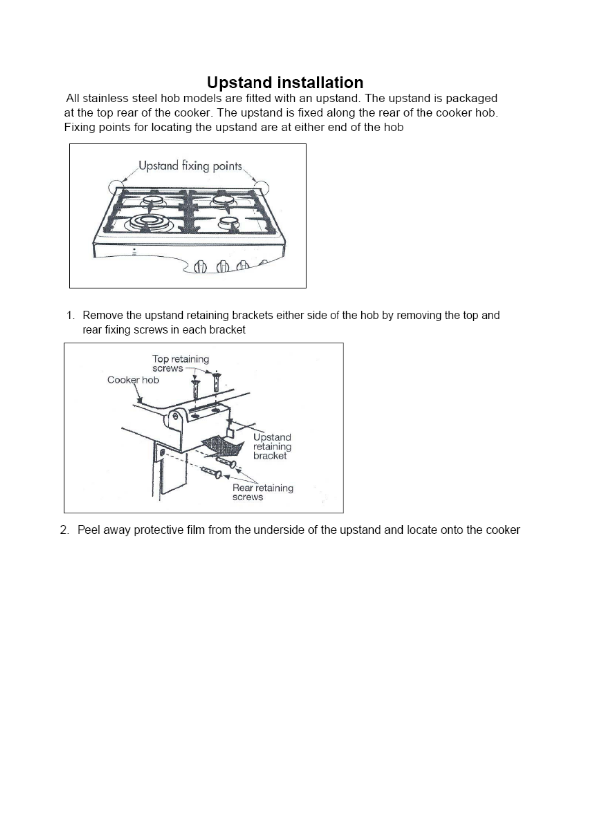
2) Burner "MINIMUM" adjustment:
Work surface burner adjustment: follow the instructions below to adjust the work surface burner minimum:
1) Light the burner and set the knob to the MINIMUM position (small flame).
2) Remove the knob of the valve that is press fit on the rod of that valve.
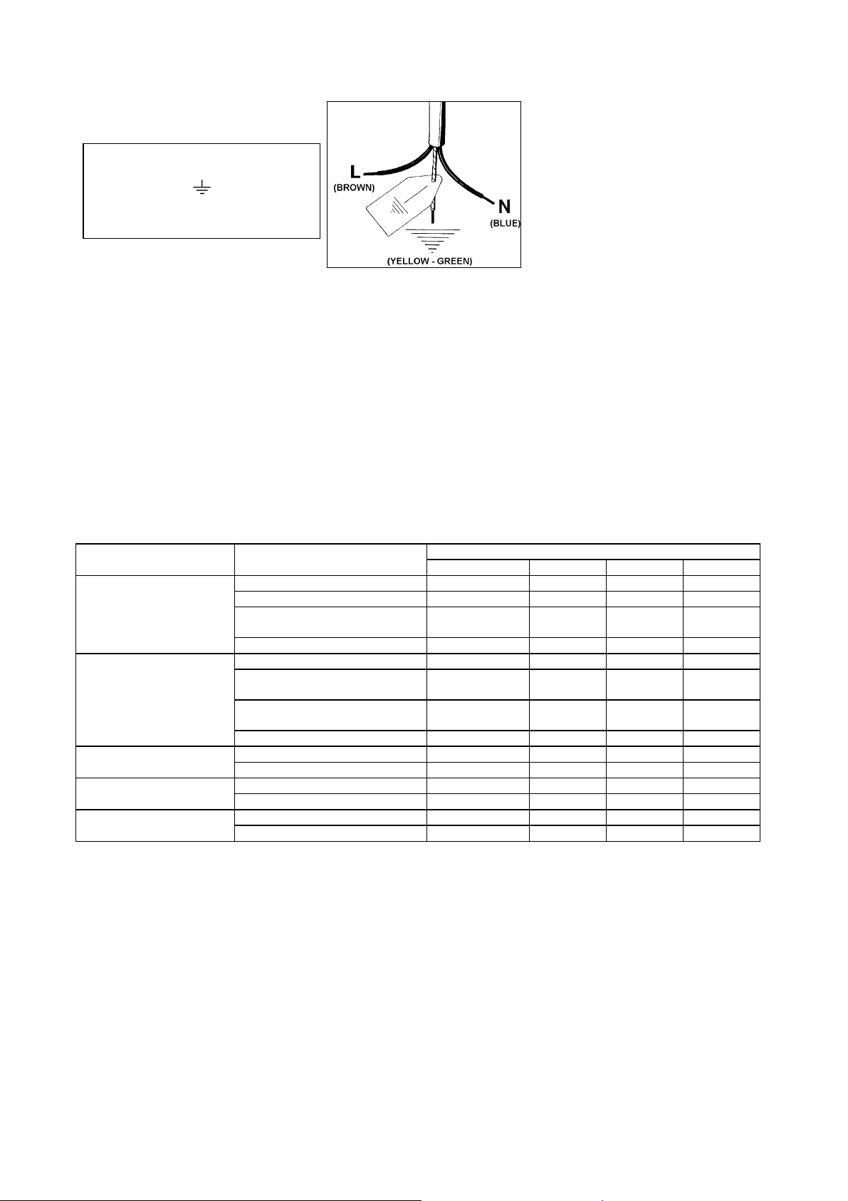
3) If the cooker is not equipped with safety valves on the surface burners, i nsert a small slotted scre wdriver into the hole
on the valve rod (Fig. 14) and turn the choke screw to the right or left until t he b urner flam e is adj usted to minimum. If the
cooker is equipped with safety valves, the choke valve is not located in the rod hole but on the valve body (Fig. 15).
4) Ensure sure that the flame does not go out when switching quickly from the MAXIMUM to the MINIMUM position.
Fig. 14 Fig. 15
APPLIANCE ELECTRIC CONNECTION
The electric connection must comply with the current legal standard s and regulations.
Before making the connection, check that:
¾ The system electrical rating and the current outlets are adequate for the maximum power output of the
appliance (see the label applied to the bottom of the casing).
¾ The outlet or the system is equipped with an efficient ground connection in accor dance with the current legal
standards and regulations. The manufacturer will not be responsible for the non-compliance with these
instructions.
¾ The power cord is supplied with a 15A plug, suitable for the load indicated on the label and a standard 15A
GPO.
13
Page 14
Letter L (phase) = brown wire;
Letter N (neutral) = blue wire;
Ground symbol
wire;
= green-yellow
Fig. 17
¾ The power cord must be positioned so that a temperature of 75°C will not be reached at any point.
¾ Do not use reductions, adapters or splitters since they might cause false contacts and lead to dangerous
overheating.
When the connection is made directly to the electric network:
¾ Use a device that ensures disconnection from the mains in which the contacts are opened to a distance that
permits complete disconnection according to the conditions for over-voltage category III.
¾ Remember that the ground wire must not be interrupted by the circuit-breaker.
¾ As an alternative, the electric connection can also be protected by a high-sensitivity residual current circuit-
breaker but this may be subject to nuisance tripping due to residual humidity in heating elements.
¾ It is highly recommended to attach the special green-yellow ground wire to an efficient ground system.
WARNING: If the power cord is replaced, the ground wire (yellow-green) connected to the terminal, should
be longer than the other wires by about 2 cm.
TABLE N°4: TYPES OF POWER CORDS
Work surface Oven Cross section
operation operation 230V ~ 230V 3~ 400V 2N~ 400V 3N~
Gas oven / Gas grill 3x0.75mm² - - Gas oven / Electric grill 3x1mm² - - Only gas burner Electric Oven 3x1mm² (M6)
3x1,5mm² (M9
Ventilated Electric Oven 3x1,5mm² - - Gas oven / Gas grill 3x1mm² - - Gas burner + 1 hot plate Gas oven / Electric grill 3x1,5mm² (M6)
3x2,5mm² (M9
Electric Oven 3x1,5mm² (M6)
3x2,5mm² (M9
Ventilated Electric Oven 3x2,5mm² - - Gas burner + 2 hot plate Forno elettrico statico 3x2,5mm² 4x1,5mm² 4x1,5mm² 5x1,5mm²
Forno elettrico ventilato multi-9 3x2,5mm² 4x1,5mm² 4x1,5mm² 5x1,5mm²
4 hot plate Forno elettrico statico 3x2,5mm² 4x1,5mm² 4x1,5mm² 5x1,5mm²
Forno elettrico ventilato multi-9 3x2,5mm² 4x1,5mm² 4x1,5mm² 5x1,5mm²
Ceran Forno elettrico statico 3x2,5mm² 4x1,5mm² 4x1,5mm² 5x1,5mm²
Forno elettrico ventilato multi-9 3x4mm² 4x1,5mm² 4x1,5mm² 5x1,5mm²
ATTENTION: The appliance conforms with the regulations of directives 90/3 96EEC (Gas Dire ctive) r egarding gas
appliances for domestic use and the like, 93/68 and 73/23 (Lo w Voltage Directive) regarding electrical saf ety and
2004/108/CE, 93/68 and 89/336 (EMC Directive) regarding electromagnetic compatibility.
THREE-PHASE ELECTRIC CONNECTION
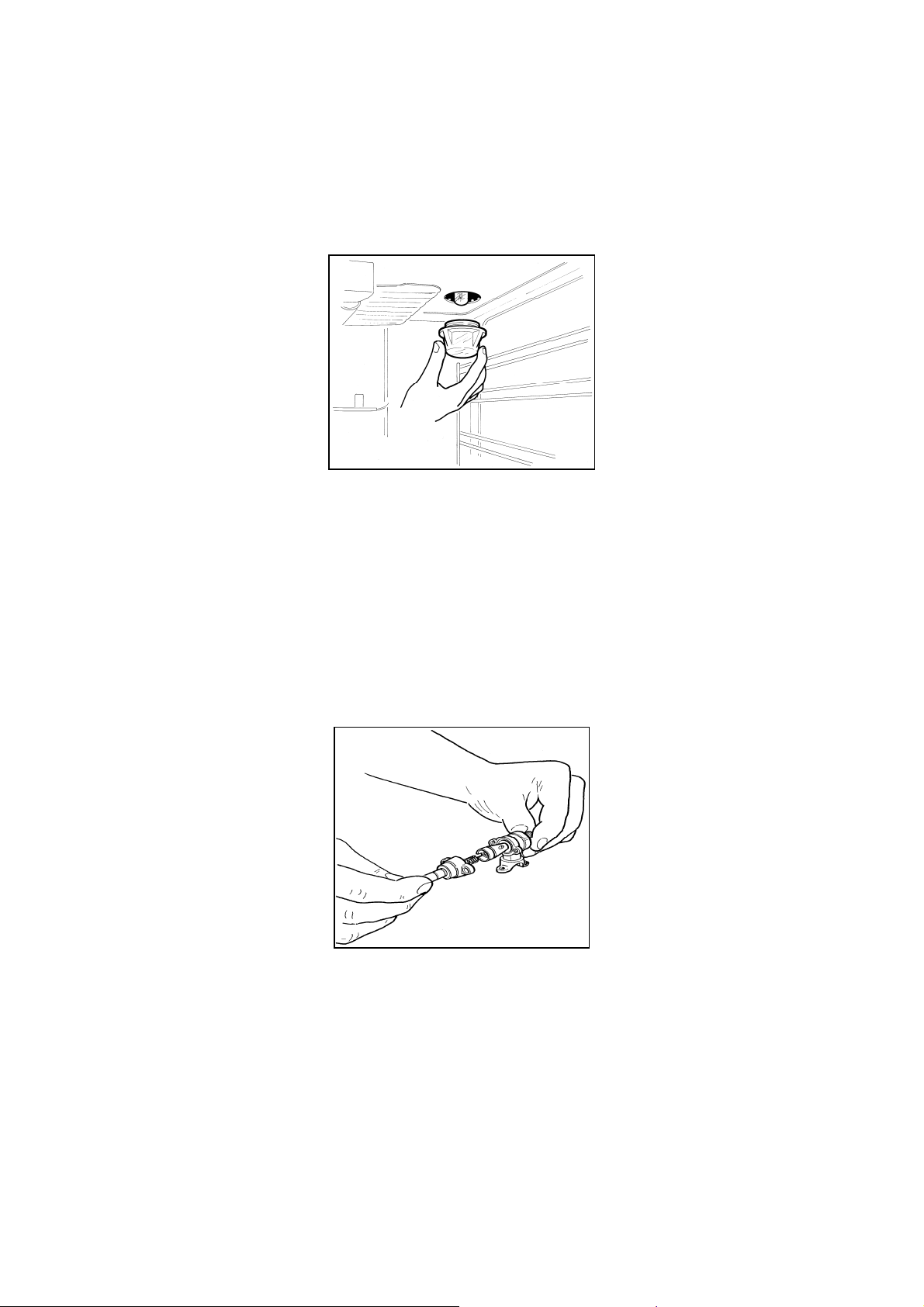
The cookers that can also be connected to three-phase systems normally are factory built for the single-phase 230V
connection and are supplied with a power cord. Based on the connection system used, install the power cord type
indicated in table No.4.
To use the selected connection system change the jumpers on the terminal strip as indicated in the diagram of (Fig.18)
- - -
- - -
- - -
14
Page 15
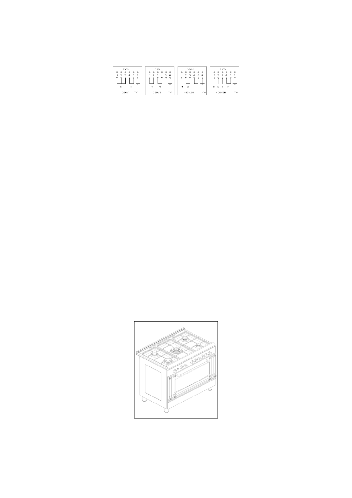
Fig. 18
APPLIANCE MAINTENANCE
ATTENTION: IMPORTANT WARNINGS
¾ For cookers resting on a base
ATTENTION: If the cooker rests on a base, take the measures necessary to prevent the cooker from sliding along the
support base.
¾ For cookers with glass covers
ATTENTION: Before opening the appliance’s glass cover, carefully remove all liquid residues from the top of it.
ATTENTION: Before closing the appliance’s glass cover, make sure that the work surface has cooled.
¾ For cookers with electric ovens
ATTENTION: The unit becomes hot during use. Do not touch the heating elements inside the oven.
¾ For cookers with electric ovens
ATTENTION: The accessible parts can become hot during use. Keep children away from the appliance.
¾ For the food warmer compartment (or drop leaf in our case)
ATTENTION: The internal parts of the food warmer can become hot during use.
¾ For glass doors
ATTENTION: Do not use harsh abrasive cleaning products or metal sp atulas with sharp edges to c lean the oven door’s
glass since this could scratch the surface and the glass could break.
Do not use steam cleaners to clean the appliance.
DOOR GUARD
The cookers with strips of stainless steel on the oven door can be equippe d with a protective grating that can be installed
on the door. Such grating is available on the service post sale (Fig.43).
Fig. 43
REPLACING PARTS
Before performing any maintenance operations, disconnect the appliance from the gas supply and electricity
network.
To replace parts such as knobs and burners, just remove them from the seats without disassembling any part of the
cooker.
15
Page 16
To replace parts such as nozzle supports, valves and electric component s follow the procedure described in the burner
adjustment paragraph. To replace the valve or the gas thermostat, it is also necessar y to disassemble the two rear gas
train brackets, loosening the 4 screws (2 per bracket) that attach it to the rest of the cooker and, unsc rew the nuts that
attach the front burner valves to the control support, after removing all the knobs. To replace the gas or electric
thermostat, also disassemble the rear cooker guard, loosening the relative screws, to be able to pull out and reposition
the thermostat bulb.
To replace the oven bulb, just unscrew the protection cap that projects out inside the oven. (Fig.19)
Fig. 19
WARNING: Before replacing the bulb, disconnect the appliance from the electric power supply.
WARNING: The po wer cord supplied with the appliance is con nected to the appliance with an X t ype connection (in
compliance with standards AS/NZS 60335-1, AS/NZS 60335-2-6 and subsequent amendments) for which it can be
installed without the use of special tools, with the same type of cord as the one installed.
If the power cord becomes worn or damaged, replace it based on the information reported in table 4.
WARNING: If the power cord is replaced, the installer shall ensure that the ground cable is longer than the
phase cables and also should comply with the warnings regarding the electric connection.
Greasing the valves:
If it becomes difficult to operate the valve, it should be greased immediately by following the instructions listed below:
1) Disassemble the valve body by loosening the two screws located on the bod y of the valve (Fig.20)
Fig. 20
2) Extract and clean the seal cone and its housing with a rag soaked with thinner.
3) Lightly grease the cone with special grease.
4) Insert the cone, moving it several times, remove it again, remove the excess grease and make s ure that the gas
passage ways are unobstructed.
5) Replace all the pieces by reversing the order in which they were disassembled and check t hat the valve operates
correctly.
6) To replace the power cable, lift the terminal board’s cover and replace the cable. To access the terminal board in
cookers with a 3x2.5mm² cable, the back panel on the rear of the appliance must be removed.
16
Page 17
USE AND MAINTENANCE MANUAL
GAS BURNER DIMENSION
Burner Dimension (mm)
Auxiliary Ø 50
Semi-rapid Ø 70
Rapid Ø 95
Fish 55x230
Electric hot plate infrared Ø 145 left rear 1200W
Electric hot plate infrared Ø 145 right rear 2100W
Electric hot plate infrared Ø 145 right front 1200W
Electric hot plate infrared Ø 180 left front 1700W
Electric hot plate hi light Ø 145 left rear 1200W
Electric hot plate hi light Ø 170/265 left rear 1400/2200W
Electric hot plate hi light Ø 145 left rear 1200W
Electric hot plate hi light Ø 180 left rear 700/2100W
Ultra-rapid Ø 130
CERAN AND ELECTRIC HOT PLATE DIMENSION
TIPE OF PLATE DIMENSION
Electric hot plate Ø 145
Electric hot plate Ø 180
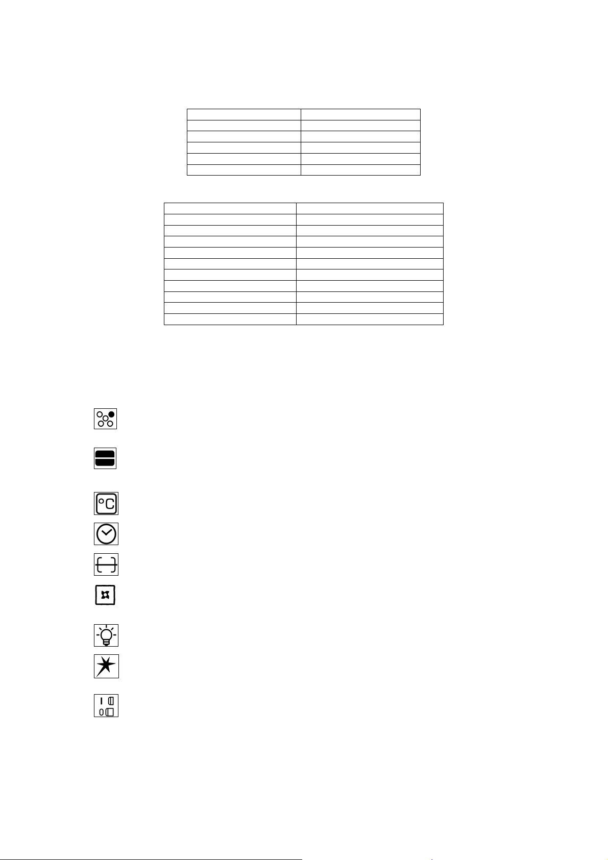
CONTROL PANEL DESCRIPTION
On the control panel, small symbols show the function of each knob or key. Here are the several controls that a cook er
can have:
Shows the position of burners on the worktop, the full dot identifies the burner in object (in this case the
rear burner on the right).
Shows the running of any oven (gas oven with gas gr ill, ga s oven with electric grill, stati c oven, 9 positi on
switch).
Shows the electric thermostat for the electric fan oven.
Shows the minute minder
Shows the operating key for the rotisserie (only gas oven).
Shows the oven fan working button, to allow the ov en to operate with fan assisted gas. The fan opera tion
of the oven prevents the operation of the electric grill, which therefore cannot be used with the fan in action.
Shows the ignition key for the oven light (all except the electric fan oven).
Shows the push-button for burner ignition.
Shows if keys are in position “on” or “off”.
17
Page 18
USING BURNERS
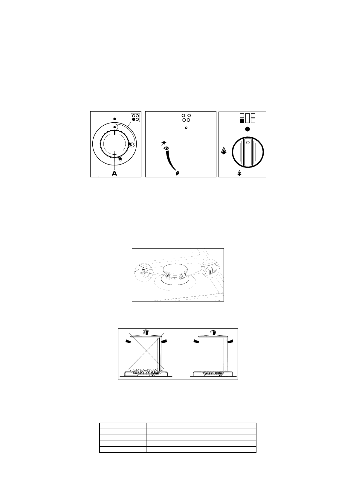
A diagram is etched on the control panel above each knob which indicate s which burner corresponds to that knob. The
burners can be ignited in different ways depending on the type of appliance and its specifi c characteristics.
¾ Manual lighting (it is always possible even when the power is cut off): Turn the knob anticlockwise that
corresponds to the burner selected, setting it to the MAXIMUM position at the etched star (large flame Fig.23A23B-23C) and hold a lit match to the burner.
¾ Electric ignition:
MAXIMUM position (large flame Fig. 23A-23B-23C) and keep on pr essing the knob in correspond ence with the
ignition symbol marked with a star (for cookers equipped with ignition through knob) or press the ig nition button
marked with a star and release it as soon as the burner has ignited.
Turn the knob counterclockwise that corresponds to the burner selected, setting it to the
Fig. 23 A Fig. 23 B Fig. 23 C
¾ Burner ignition equipped with safety device (thermocouple) (Fig. 22): Turn the knob anticlockwise that
corresponds to the burner selected, setting it to the MAXIMUM position at the etch ed star (larg e flame Fi g. 23A23B-23C), press the knob and activate one of the above-mentioned ignition devices. Once ignited, keep
pressing the knob for about 10 seconds to allow the flame to heat the thermocou ple. If the burner goes out after
releasing the knob, repeat the entire operation.
Note: It is recommended not to try to ignite a burner if the relative flame cap is not in the correct position.
Fig. 22
Tips for using burners correctly:
¾ Use suitable pots for each burner (see tab. 5 and Fig. 21).
Fig. 21
¾ When the liquid is boiling, turn the knob to the MINIMUM position (small flame Fig. 23A-23B-23C).
¾ Always use pots with a cover.
TABLE N°5
BURNER PAN DIAMETER recommended (cm)
Auxiliary 12-14
Semi-rapid 14-26
Rapid 18-26
Double ring 22-26
ATTENTION: Use pots with a flat bottom
18
Page 19
WARNING: If the power is cut off, the burners can be lit with matches. When cooking foods with oil and fat,
which are very flammable, the user should not leave the appliance unattended. If the appliance is equipped with
a glass cover, the cover may break whe n heated. Turn off all burners before lowering the cover. Do not use
sprays near the appliance when it is being used. When using the burners, make sure that the handles of the pots
are correctly positioned. Keep children away from the app liance. If equipped with a cover, before being closed,
any food deposits should be cleaned off the built-in surface.
NOTE: The use of a gas cooking appliance produces heat and humidity in the room where it is installed.
Therefore, proper aeration in the room is needed while ensuring that natural ventilation openings remain
unobstructed (Fig.3) and activating the mechanical aeration device/exhaust hood or electric fan (Fig. 4 and Fig.
5). Intensive and continuous use of the appliance m ay require additional aeration, for example by opening a
window, or more efficient aeration by increasing the power of the mechanical exhauster, if installed.
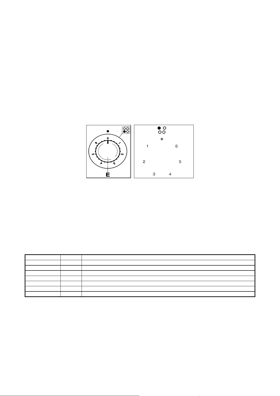
USE OF THE ELECTRIC PLATES
The plates are controlled by a switch with 6 positions (Fig. 24A-24B ).
Fig. 24A Fig. 24B
The plates can be utilised by rotating the knob onto the desired position. On the front of the appliance there is a design
showing which plate the knob refers to. The use of the plate is sho wn by the indicator light which is also found on the
front panel of the appliance
.
How to use an electric plate?
When you use the plate for the first time or after a l ong period over which the plate has not been use d, you are advised
to use the plate on position 1 for about 30 minutes in order to eliminate any humidity absorb ed by the isolating material
inside. As an indication we give a table with the necessary rules to follow for the best use of the electric plates.
WARNING: When using the plate for the first time or after a long period over which the plate has not been
used, in order to eliminate any humidity absorbed by the isolating material it is necessary to use the plate for
about 30 minutes on position 1 of the switch.
PLATE 1500W Watt COOKING POSSIBILITIES
0 0 Plate switched off
1 135 To melt butter, chocolate etc. - To heat up small quantities of liquid
2 165 To heat up larger quantities of liquid - to prepare creams/sauces with long cooking times
3 250 To thaw foods, cooking boiling temperatures
4 500 To cook roasts of delicate meat and fish
5 750 For roast of chops and steaks, for large boiled foods
6 1500 To boil large quantities of water, to fry
19
Page 20
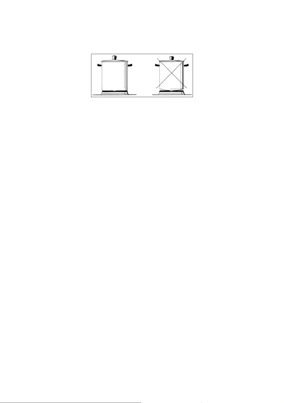
For a correct use remember the following:
¾ Dry the bottom of the pan before putting it on the plate.
¾ Use pans with a flat bottom and in thick metal (Fig. 25 ).
Fig. 25
¾ Never use pans which are smaller than the plate.
¾ Switch on the current after you have put the pan on the plate.
¾ After use, to keep the plate in good condition, always treat the plate with normal products for electric
plates which are available on the market so th at the surface is always clean; doin g this will avoid any
eventual oxidisation (rust).
¾ Even after use the plates stay hot for a long time and so do not put your hands or other objects on the
plates so as to prevent possible burns.
¾ When the plates are in use make sure that the pan handles are positioned correctly. Keep children
away.
¾ When cooking foods with oil and fat, which can easily set alight, the user must not leave the appliance
unattended.
WARNING: As soon as you see a crack in the surface of the plate immediately disconnect the appliance from
the mains.
USING THE CERAMIC HOB
The work surface has 4 cooking areas with different he ating levels and diameters. The positions ar e clearly indicated b y
circular areas that are not etched. Heating takes place within these marked areas. If 1 or 2 cooking areas are used, th e
other surface remains cold. It is recommended to use special ut ensils for electric cooking to ensure efficient use and t o
save energy. The bottom of the pan surface should be thick and flat to guarantee the best cooking. The diameter of the
base of the pots (or other containers) should be as close as possible to the diameter of the plate being used, if it is
smaller, energy will be wasted since the heat generated will be partially dispersed b y the uncovered surface of the plat e.
The surface of the hob and the base of the container must be clean. Following these hints will save energy and heat.
How to use the ceramic hob?
Each cooking area is controlled by a thermostat or by an energy regulator that is used to select a variable temperature.
When the boiling point is reached, the temp erature can be reduced to al low the food to slowly boil. Pra ctice will indicate
the right time to allow the foods to slowly boil, but obviously t his depends on the food and the type of pot. T he correct
combination will save time and energy.
WARNING: Your CERAN ceramic hob is resistant to thermal shocks and is not affected by heat or cold.
Accidental impacts with a heavy casserole dish are unlikely to damage the hob. However, a special type of
impact, caused by a heavy abject such as a salt container o r a spice bottle on the edge or corner of the hob,
may break the surface.
GAS OVEN:
All the gas oven cookers are equipped with a thermostat and safety device to adjust the cooking temperature. The oven
temperature is set by turning the knob counterclockwise to match the indicator with the temperature selected. The gas
oven can be combined with a gas grill or an electric grill. See the specific pages for usage information.
FAN GAS OVEN:
Operating the fan of the oven by means of the appropriate switch situated on the control panel, the circulation of warm air
guarantees a uniform heat distribution. The preheating of the oven can be avoided. However for delicate baking, it is
preferable to warm the oven before introducing the baking-pan. The baking system with the fan convection changes in
part the various traditional baking notions. When roasting meat it is not necessary to turn the meat any more and for a
roast on the spit, it is not indispensable to use the spit-roaster, but is sufficient to put the meat directly on the grate.
With the use of the fan gas oven, the baking temperatures are slightly lower by about 10-15°C compared to those in use
with the traditional gas oven. The fan operation of the oven prevents the operation of the electric grill, which therefore
cannot be used with the fan in action.
The oven can also be used in a traditional way, (by not activating the fan) for foods requiring heat from the bottom, e.g.
pizza.
USING THE GAS OVEN
20
Page 21
WARNING: If the burner flames are extinguished accidentally, turn off the control knob and do not try to
relight the oven until after at least 1 minute.
The oven burner can be ignited in different ways:
¾ Manual lighting (it is always possible even when the power is cut off):
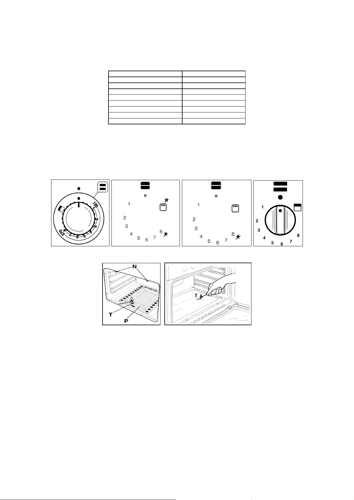
To light the oven, open the oven door and turn the knob s o the no. 8 on the scale matches the indicator (fig.26A-26B26C-26D). At the same time put a lit match next to the ignition tube that is visibl e on the oven level (fig.27A for cooker
type VEF61EG) (fig.27B for cooker type VEF91EG). Then press the thermostat knob (this makes the gas start to flow)
and keep it pressed, after the burner has been completely lit, for 10 seconds. Releas e the knob and make sure that the
burner remains on, otherwise repeat the operation.
TABLE N°6: THERMOSTAT SETTING
THERMOSTAT SETTING TEMPERATURE °C
1 120°C
2 140°C
3 160°C
4 180°C
5 200°C
6 225°C
7 245°C
8 270°C
Fig. 26A Fig. 26B Fig. 26C Fig. 26D
Fig. 27A Fig. 27B
¾ Electric ignition (only for the models equipped with this device):
In this case, first open the oven door and then turn the knob to the maximum temperature setting (number 8). Then press
the thermostat knob (models with ignition through the knob). Wait about 10 seconds after the burner has been
completely lit and then release the knob. Make sure that the burner remains on, otherwise repeat the operation. As for
cookers without ignition through the knob, press the thermostat knob and the key with the spark symbol, wait about 10
seconds after the burner has been completely lit and then release the knob. Make sure that the burner remains on,
otherwise repeat the operation.
The ignition device should not be used for more than 15 seconds. If after that period the burner still has not
been lit, do not use the device and open the door of the room or wait at least 60 seconds before trying to light
the oven again.
WARNING: when trying to light the oven, the door must always be open. When using the oven, leave the
cooker cover open to prevent it from overheating.
NOTICE: when using the oven for the first time it should be operated for 15-30 minutes at a temperature of
about 250°C without cooking anything inside in order to eliminate any moisture and odours from the internal
insulation.
21
Page 22
During normal oven use, after lighting the burner and setting the desired temperature, wait about 15 minutes before
putting in any food to preheat the oven.
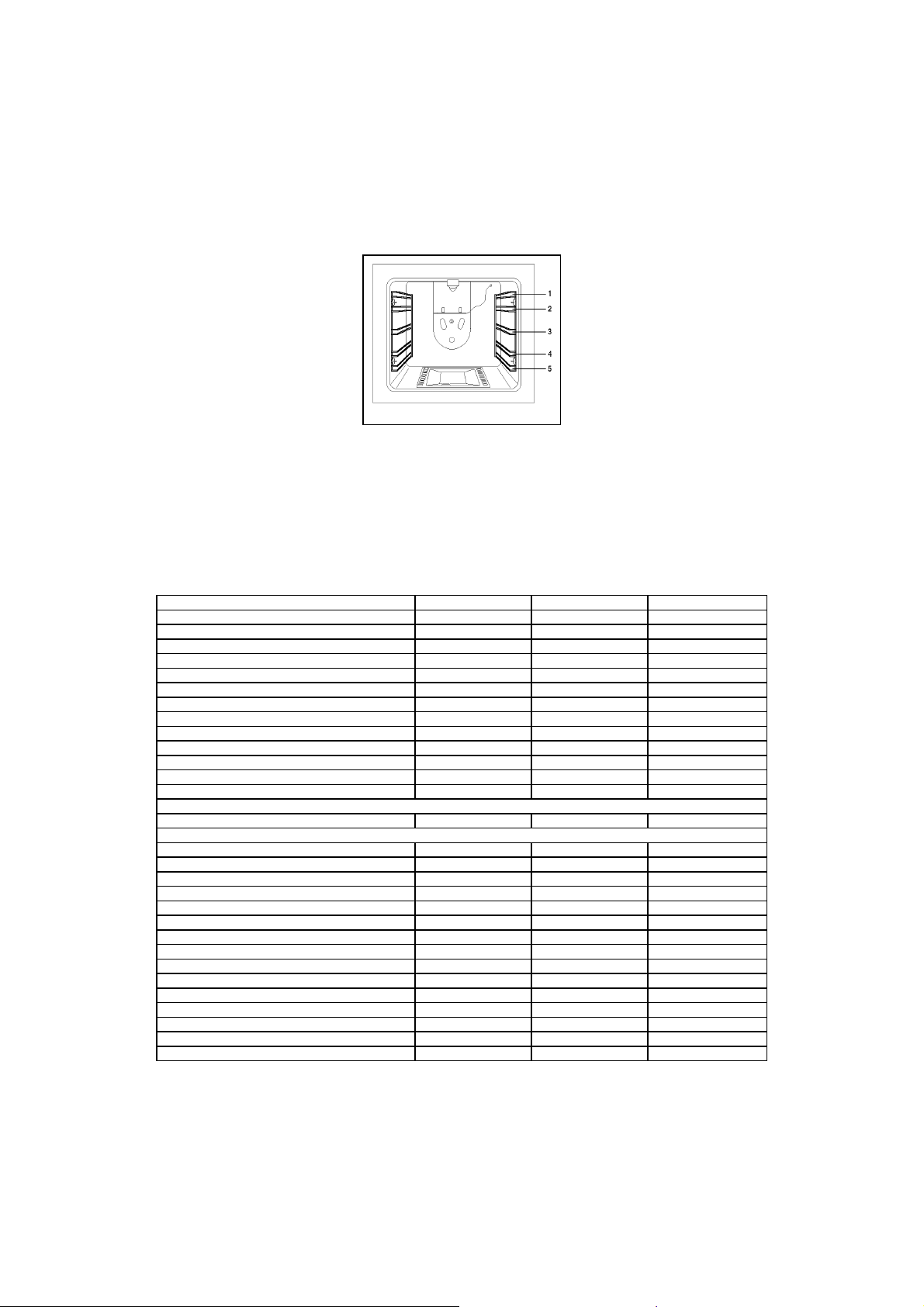
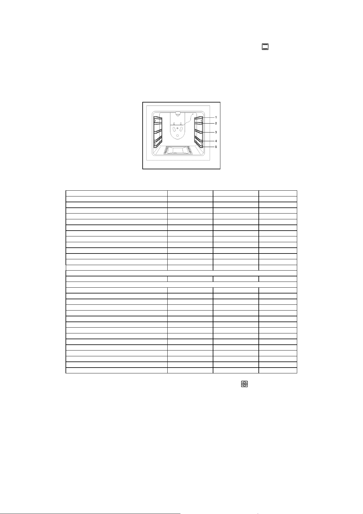
The oven is equipped with 5 guides at different heights (Fig.28) which can be us ed to insert shelves or the tray. To kee p
the oven as clean as possible it is recommended to cook meat on the tray or on the shelf that has been inserted inside
the tray. The table below lists the general cooking times and th e position of the tray for different t ypes of foods. Person al
experience will help to determine any vari ations in the values reported in the table. In any case, it is recommended to
follow the instructions of the specific recipe being used.
Fig. 28
NOTICE: Insert shelves into the guide rails on each sid e with the raised backstop towards the rear of the
oven
Temperatures between brackets are referring to the use of oven with fan assisted gas.
TABLE N°8: GAS OVEN COOKING TABLE
TEMP °C HEIGHT MINUTES
MEAT
PORK ROAST 220 (210) 4 60-70
BEEF ROAST (YOUNG STEER) 250 (240) 4 50-60
BEEF ROAST 240 (230) 4 60-70
VEAL ROAST 220 (210) 4 60-70
LAMB ROAST 220 (210) 4 45-55
ROAST BEEF 230 (230) 4 55-65
ROAST HARE 235 (225) 4 40-50
ROAST RABBIT 220 (210) 4 50-60
ROAST TURKEY 235 (225) 4 50-60
ROAST GOOSE 225 (215) 4 60-7 0
ROAST DUCK 235 (225) 4 45-60
ROAST CHICKEN 235 (225) 4 40-45
SWEET PUFF PASTRIES 220 (210) 3 20
SAVOIA COOKIES 190 (180) 3 15
APPLE FRITTERS 220 (210) 3 20
SAZOIARDI SANDWICH 220 (210) 3 20-30
TOAST SANDWICH 250 (240) 4 5
FISH
PASTRY
FRUIT PIE 200 (210) 3 35-40
TEA CAKE 190 (180) 3 50-55
BRIOCHES 175 (165) 3 25-30
SPONGE CAKE 235 (225) 3 20
RING CAKE 190 (180) 3 30-40
RAISIN LOAF 220 (210) 3 15-20
STRUDEL 180 (170) 3 15-20
BREAD 220 (210) 3 30
PIZZA 220 (210) 3 20
200-225 (190-215) 3 15-25
22
Page 23
USING THE THERMOSTAT WITH SWITCH IN SERIES
(COOKERS WITH A SINGLE-CONTROL CONVENTIONAL ELECTRIC OVEN)
The electric oven is controlled by an electric thermostat combined with a switch used to turn on the elements. The
electric oven can be combined with an electric grill. The oven is heated by 2 elements: one on the top and one on the
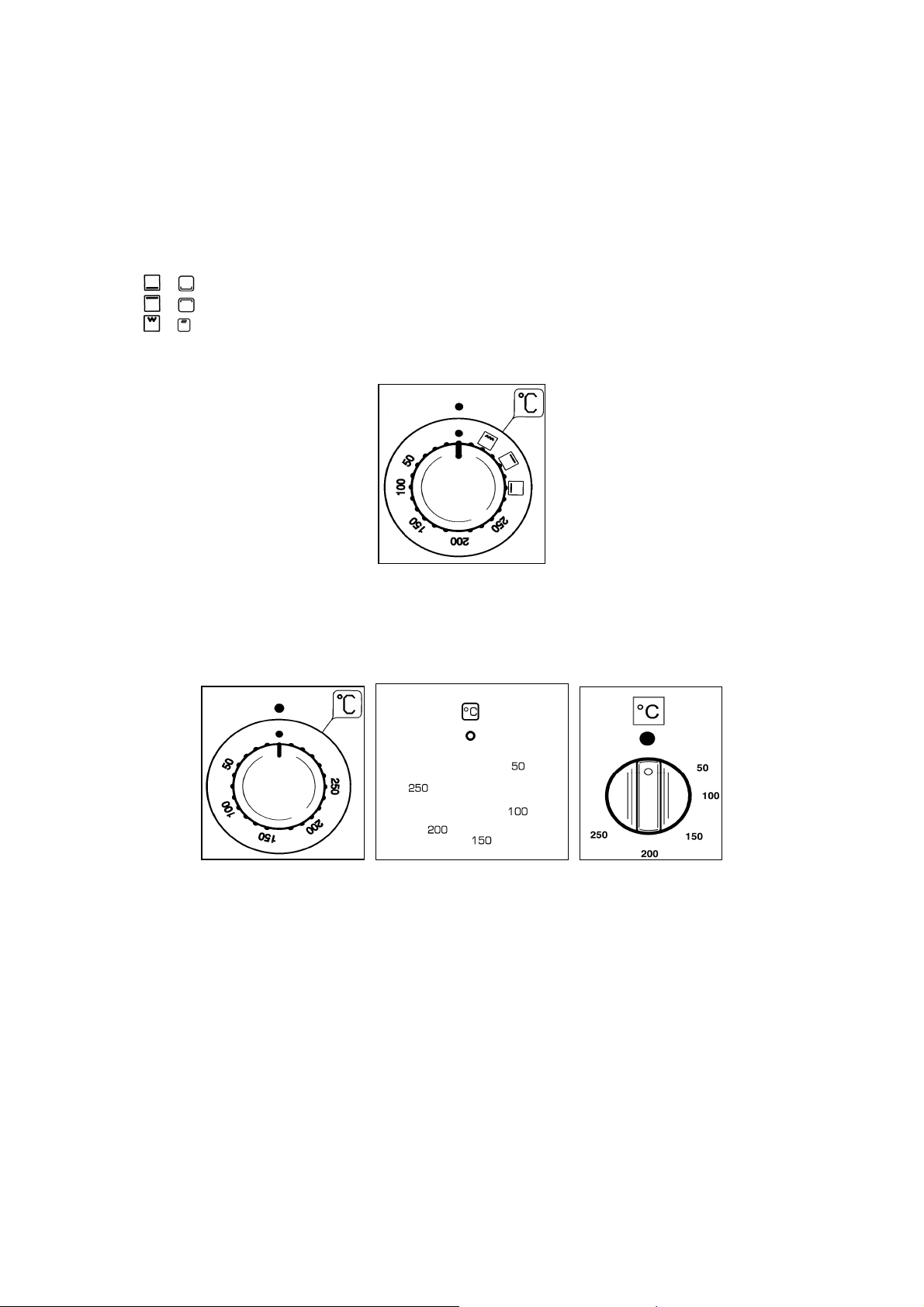
bottom. Turning the knob (Fig.29) turns on the bottom element and the top external elements while the thermostat is
used to set the temperature ranging from 50°C to 250°C. It can be adjusted using the scale indicated on the ring around
the knob. An orange light turns off indicating that the temperature setting has been reached. T herefore, it is normal for
this light to turn on and off while the oven is working. There are 3 fixed positions beyond the 250°C setting:
or indicates the only the bottom element (1300W M6; 1800 W M9) has been turned on;
or indicates that only the top ext ernal element (900W M6; 1200 W M9) has been turned on;
or indicates th at only the grill element (1500WM6; 1800W M9) has been turned on;
In these positions the temperature is not controlled by the thermostat.
Fig. 29
USING THE ELECTRIC THERMOSTAT
The thermostat supplied with the relative models maintains a constant temperature inside the oven at a specific
temperature setting ranging from 50°C to 250°C (Fig.30A-30B-30C).
Fig. 30A Fig. 30B Fig. 30C
Turn the knob clockwise and align the select ed temperature indicated on the ring with the index etched on th e control
panel. Thermostat operation is indicated by an orange light which will turn off when the temperature inside the oven is
10°C greater than the temperature setting, and will turn on when the oven is 10°C less than the temperature setting. T he
thermostat can control the oven elements only if the r elative switch is in one of the possible oven element operating
modes: if the switch is in position 0, the thermostat has no effect on the oven elements, which remain off.
23
Page 24
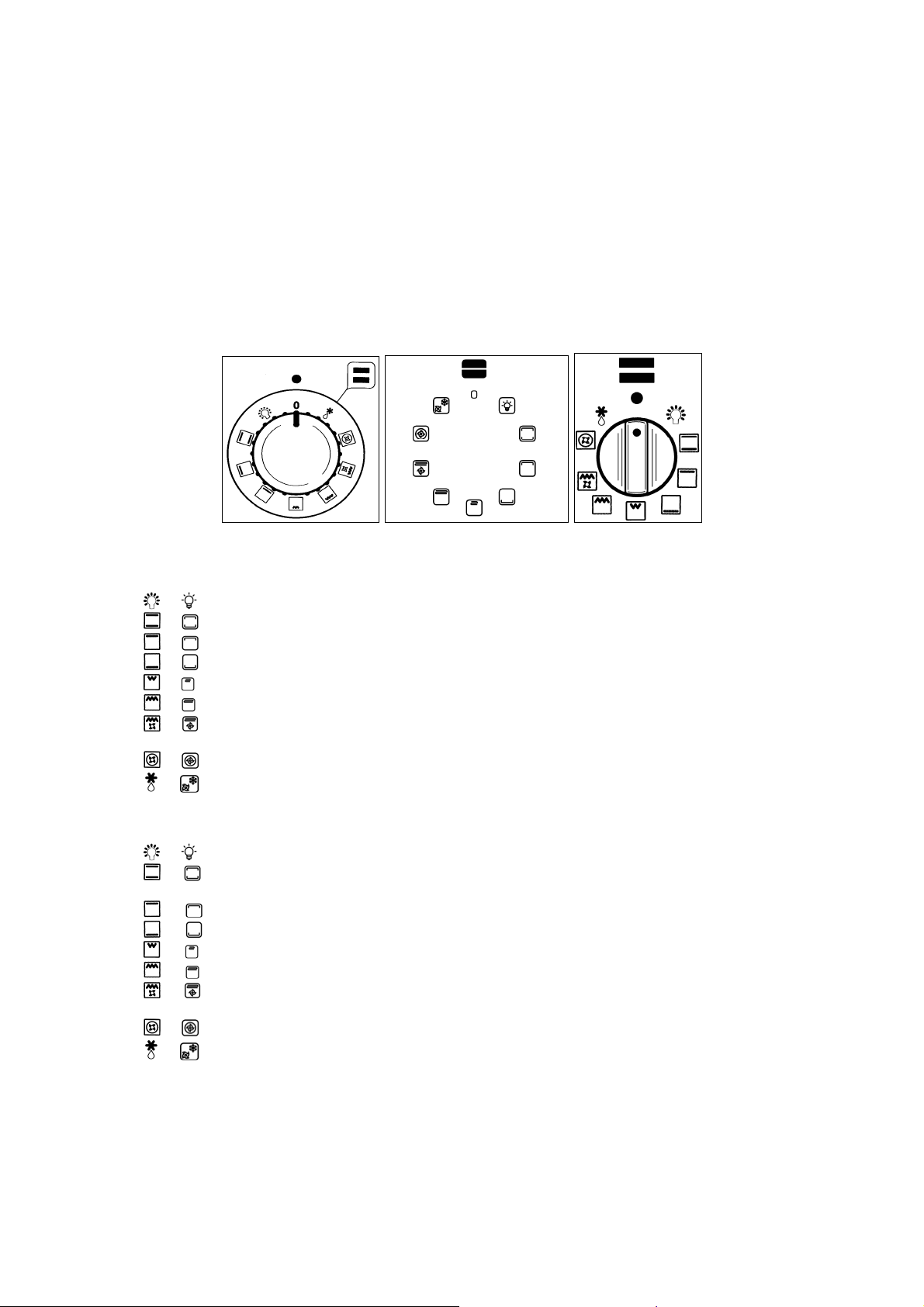
USING THE OVEN FUNCTION KNOB (Fig.31A-31B-31C)
The oven function knob installed in the multifunction oven models is used, along with the thermostat, to control the
electric fan and the oven elements since they can be turned on by turning the oven function knob and the thermost at
knob. Turning just one of the two knobs will not have any effect on the oven e xcept to turn on the oven light or the
electric fan when selected. The electric oven is heated by 4 elements: one on the bottom, two on the top or one circular;
turning the oven function knob turns on the element relativ e to the symbol indicated on the ring but to be activated the
thermostat knob must be turned until the orange light turns on indicating that the element has been turned on. Placing
the oven function knob on any of the nine operating modes turns on the oven light, together with the relative element.
Once the temperature and the elements to be used have been set, the oven elements are turned on and off by the
thermostat; therefore, it is normal for the orange light to turn on and off while the oven is working.
To turn off the electric oven set the oven function knob to position 0 to prevent the thermostat from controlling the
elements. Setting the thermostat knob to position 0 turns off the elements but it is still possible, using the oven function
knob, to turn on the electric fan and the oven light.
The knob has 9 different fixed positions corresponding to 9 different types of oven operation:
Fig. 31A Fig. 31B Fig. 31C
For type VEF61EG:
or indicates that only the oven light is turned on;
or indicates that the bottom element (1300W) and the top external eleme nt (900W) have been turned on;
or indicates that only the top externa l element (900W) has been turned on;
or indicates the only the bottom element (1300W) has been turned on;
or indicates that only the grill element (2000W) has been turned on;
or indicates that the top external element (900W) and the grill element (2000W) have been turned on;
or indicates that the top external element (900W), the grill element (2000W) and the electric fan have
been turned on;
or indicates that the circular element (2400W) and the electric fan have been turned on;
or indicates that only the electric fan has been turned on.
For Type VEF91EG:
or indicates that only the oven light is turned on;
or indicates that the bottom element (180 0W)and the top external element (1200W) have been turned
on;
or indicates that only the top external element (1200W) has been turned on;
or indicates the only the bottom element (1800W) has been turned on;
or indicates that only th e grill element (18000W) has been turned on;
or indicates that the top externa l element (1200W) and the grill element (1800W) have been turned on;
or indicates that the top external element (1200W), the grill element (1800W) and the electric fa n have
been turned on;
or indicates that the circular element (3000W) and the electric fan have been turned on;
or indicates that only the electric fan has been turned on.
When the knob is set to one of these nine positions, the oven light is always on, thus indic ating that the oven is
being energised.
24
Page 25
USING THE NATURAL CONVENTIONAL ELECTRIC OVEN
When using the oven for the first time it should be operated for a maximum of 30 minutes at a temperature of about
250°C to eliminate any odours generated by the internal insulation. During normal oven use, select the desired cooking
temperature using the thermostat knob and wait until the orange light turns off before putting in any food. The oven is
equipped with 5 guides at different heights (Fig.28) which can be used to insert shelves o r the tray. To keep the oven as
clean as possible it is recommended to cook meat on the tray or on the shelf that has been inserted inside the tray. Table
No. 8 below lists the cooking times and the position of the tray for different types of foods. Personal experience will help
to determine any variations in the values reported in the table. In any case, it is recommended to follow the instructions of
the specific recipe being used.
Fig. 28
TABLE N°8:
TEMP °C HEIGHT MINUTES
MEAT
PORK ROAST 225 4/5 60-80
BEEF ROAST (YOUNG STEER) 225 4/5 60-80
BEEF ROAST 250 4/5 50-60
VEAL ROAST 225 4/5 60-80
LAMB ROAST 225 4 40-50
ROAST BEEF 230 4/5 50-60
ROAST HARE 250 4/5 40-50
ROAST RABBIT 250 4 60-80
ROAST TURKEY 250 4 50-60
ROAST GOOSE 225 4 60-70
ROAST DUCK 250 4/5 45-60
ROAST CHICKEN 250 4/5 40-45
FISH
PASTRY
FRUIT PIE 225 3 35-40
TEA CAKE 175-200 3 50-55
BRIOCHES 175-200 3 25-30
SPONGE CAKE 220-250 3 20-30
RING CAKE 180-200 3 30-40
SWEET PUFF PASTRIES 200-220 3 15-20
RAISIN LOAF 250 3 25-35
STRUDEL 180 3 20-30
SAVOIA COOKIES 180-200 3 40-50
APPLE FRITTERS 200-220 3 15-20
SAZOIARDI SANDWICH 200-220 3 20-30
TOAST SANDWICH 250 4 5
BREAD 220 4 30
PIZZA 220 3 20
When using the oven for the first time it should be operated for a ma ximum of 30 minutes at a temperature of about
250°C to eliminate any odours generated by the internal i nsulation.
Before cooking, allow the oven to reach the desired temperature setting by waiting for the orange light to turn off. This
type of oven is equipped with a circular element around which a fan has bee n installed that creates forced-air circul ation
in the horizontal direction. Thanks to this type of operation, the ventilated oven can be us ed for different types of cooking
at the same time, without changing the taste of each food . Only some models are equipped with a removable metall ic
filter applied to the rear screen which collects the f at while a roast is cooking. Therefore, it is recomme nded to remove
this fat periodically, washing the screen with soapy water and rinsing thor oughly. T o remove the metallic filters just appl y
slight pressure towards the top on the tab indicated by the arrow. Hot-air circulation guarantees a uniform distribution of
heat. Pre-heating the oven is not necessary, but for very delicate pastries, it is recommended to heat the ove n before
inserting the trays.
The ventilated conventional system partially changes the various notions a bout tradition al cooking. Meat no lo nger ne ed s
to be turned while it is cooking and the rotisserie is no longer needed t o cook a roast on the spit. Just put the meat
directly on the shelf.
NATURAL CONVENTIONAL ELECTRIC OVEN COOKING TABLE
200-225 3 15-25
USING THE VENTILATED ELECTRIC OVEN
25
Page 26
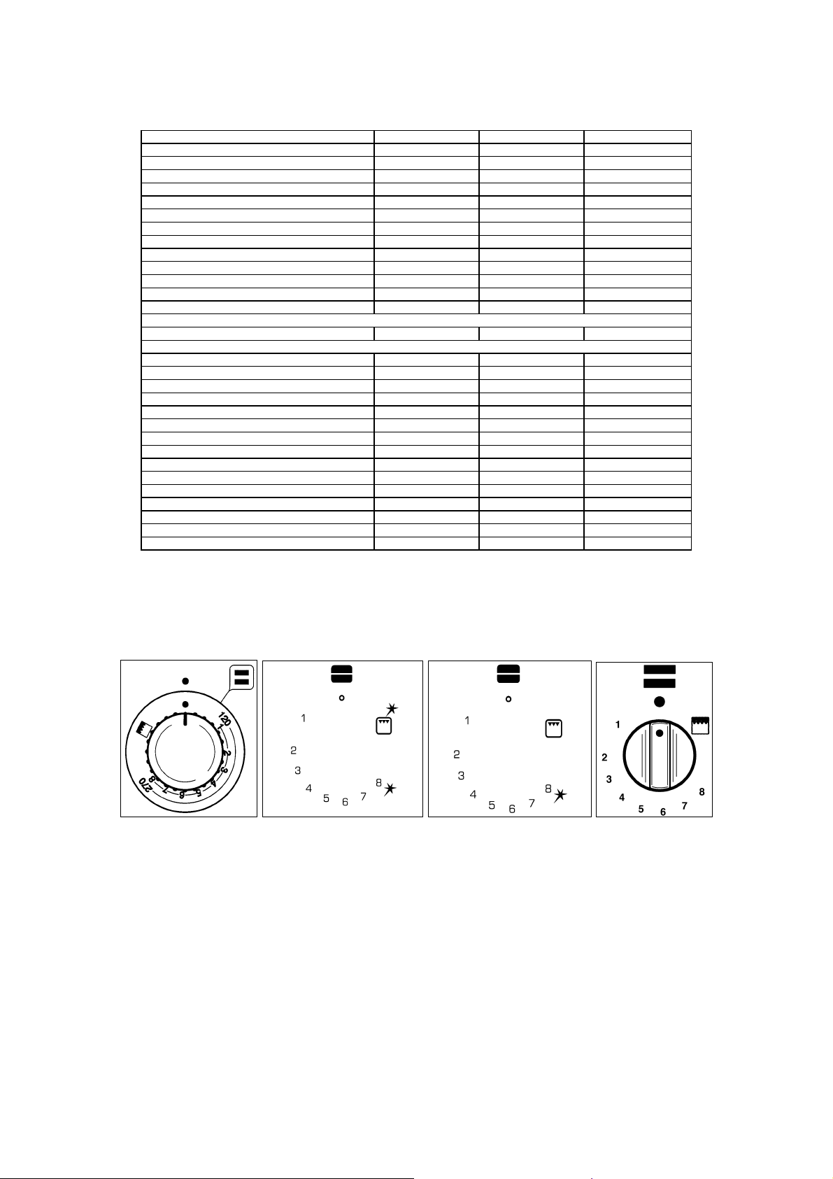
TABLE N°9: VENTILATED ELECTRIC OVEN COOKING TABLE
MEAT
PORK ROAST 160-170 3 70-100
BEEF ROAST (YOUNG STEER) 170-180 3 65-90
BEEF ROAST 170-190 3 40-60
VEAL ROAST 160-180 3 65-90
LAMB ROAST 140-160 3 100-130
ROAST BEEF 180-190 3 40-45
ROAST HARE 170-180 3 30-40
ROAST RABBIT 160-170 3 80-100
ROAST TURKEY 160-170 3 160-240
ROAST GOOSE 160-180 3 120-160
ROAST DUCK 170-180 3 100-160
ROAST CHICKEN 180 3 70-90
FISH
PASTRY
FRUIT PIE 180-200 3 40-50
TEA CAKE 200-220 3 40-45
BRIOCHES 170-180 3 40-60
SPONGE CAKE 200-230 3 25-35
RING CAKE 160-180 3 35-45
SWEET PUFF PASTRIES 180-200 3 20-30
RAISIN LOAF 230-250 3 30-40
STRUDEL 160 3 25-35
SAVOIA COOKIES 150-180 3 50-60
APPLE FRITTERS 180-200 3 18-25
SAZOIARDI SANDWICH 170-180 3 30-40
TOAST SANDWICH 230-250 4 7
BREAD 200-220 4 40
PIZZA 200-220 3 20
TEMP °C HEIGHT MINUTES
160-180 3 / 4
USING THE GAS GRILL
The gas grill can be combined only with the gas ov en. It is controlled with the same gas oven knob (fig. 26A-26B-26C 26D), but turning it clockwise instead of counterclockwise (see the gas ov en use instructions) and matching the symbol
with the indicator.
Fig. 26A Fig. 26B Fig. 26C Fig. 26D
The grill burner always operates at maxim um and therefore there is n o minimum position. In ad dition, it is equipped with
a safety device to prevent the flame from going out. The gas grill can also be ignited in different ways:
¾ Manual lighting: Completely open the oven door, turn the knob so that the relative symbol matches the
indicator, while pressing the knob, and, at the same time, put a lit match next to the burner. Make sure that the
burner is completely lit and after about 10 seconds rele ase the knob. Make sure that the burner remains on,
otherwise repeat the operation.
¾ Electric ignition: In this case, completely open the oven door; turn the knob so that the relative symbol
matches the indicator, then press the thermostat knob (models with ignition through the knob). Wait about 10
seconds after the burner has been completely lit and then release the k nob. Make sure t hat the burner remains
on, otherwise repeat the operation. As for cookers without ignition through the knob, press the thermostat knob
and the key with the spark symbol, wait about 10 sec onds after the burner has been completely lit and then
release the knob. Make sure that the burner remains on, otherwise repeat the operation.
WARNING: As with the oven, the grill must be lit with the door completely open.
26
Page 27
The gas grill can be used to grill foods on the oven shelf or using the rotisserie.
Grilling on the shelf
In this case, the shelf supplied is placed on level 1 or 2 and the foods to be gri lled are placed on top, while the tray is
inserted on the lower levels to collect the cooking juices.
Then light the grill burner according to the instructions described above.
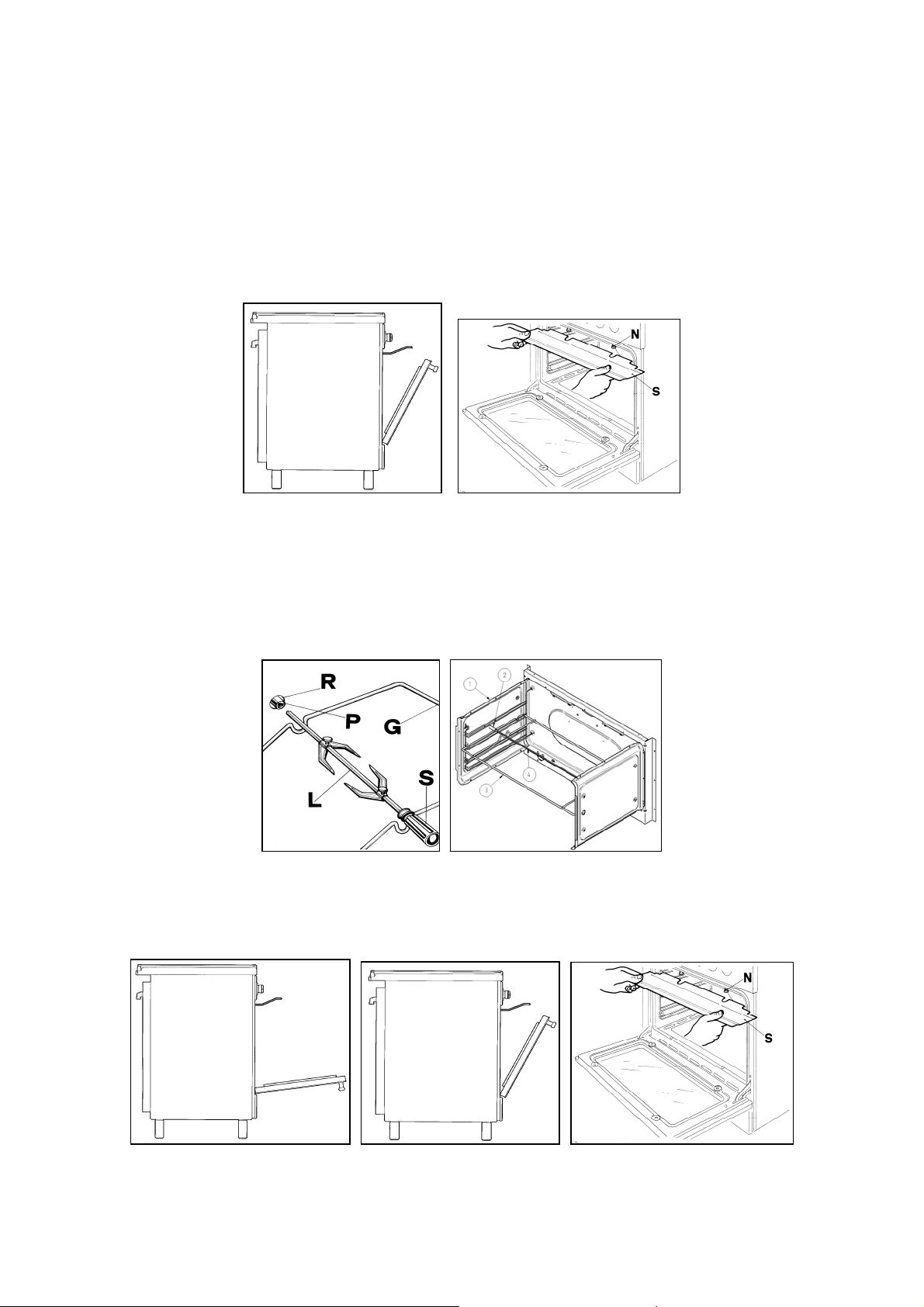
IMPORTANT: Grill foods on the shelf always with the door semi-open (Fig. 35) and, to avoid overheating,
mount the handle guard on the relative latches (Fig. 32).
Fig. 35 Fig. 32
Grilling with the rotisserie
This is used to grill with the rotating skewer. Insert the skewer holder on the side shelves at level 3. Place the food on the
skewer and insert this into the oven, placing the point of the skewer into the spindle that projects out from the rear or left
size of the oven and resting the front of the skewer into the skewer holder support (Fig. 33 for cooker type M6) (F ig. 34
for cooker type M9). Then, insert the tray into one of the lower guides and press the button that starts the rotisserie. Then
light the grill burner according to the instructions described above.
Fig. 33 Fig. 34
IMPORTANT: Grill foods with the rotisserie always with the door open (Fig. 36 ) for cooker type M6V and
with the door semi-open (Fig. 35) for cooker type M9V and, to avoid overheating, mount the handle guard on the
relative latches (Fig. 32).
Fig.36 Fig. 35 Fig. 32
WARNING: the accessible parts may become very ho t while grilling. Keep children away from the appliance
while cooking.
27
Page 28
USING THE CONVENTIONAL ELECTRIC GRILL
The electric grill can also be combined with the gas oven or electric oven.
In both cases, the grill is controlled using the oven’s temperature knob (see also, Using the gas or electric oven). Like
the gas grill, the electric grill can be used for grilling on the oven’s grill or using the ro asting spit.
The static electric grill must be used with the door closed. T he temperature set on the thermostat (when present) must
not exceed 150°C.
The power of the electric grill for M6 cookers with gas oven is 1500W whereas for M9 cookers with gas oven it is 1800W.
Grilling on the shelf
In this case, the shelf supplied is placed on level 1 or 2 and the foods to be gri lled are placed on top, while the tray is
inserted on the lower levels to collect the cooking juices. Then turn on the grill elemen t switching the thermostat to the
relative position (electric oven version).
Grilling with the rotisserie
This is used to grill with the rotating skewer. Therefore, insert the skewer holder on the side shelves at level 3. Place the
food on the skewer and insert this into the oven, inserting the poi nt of the skewer into the spindle that projects out from
the rear or left size of the oven and resting the front of the skewer into the skewer holder support. Then, insert the tray
into one of the lower guides and switch the thermostat to the rel ative position and press the button with the rotisserie
symbol (electric oven version).
WARNING: The accessible parts may become very hot while grilling. Keep children away from the appliance
while cooking.
USING THE VENTILATED ELECTRIC GRILL
The ventilated electric grill is a special function equi pped only on the multifunction oven. Set the oven f unction knob to
the relative position to activate the grill element (2900W) and the electric fan. Generally, to ensure excellent grilling, place
the oven shelf in the middle position while the oven tray should be inserted at the bottom.
IMPORTANT: When using the ventilated electric grill, set the thermostat knob no higher than 175°C, which
is between the 150°C and 200°C setting, to avoid overheating the front of the appliance. Ventilated grilling must
be carried out with the door closed.
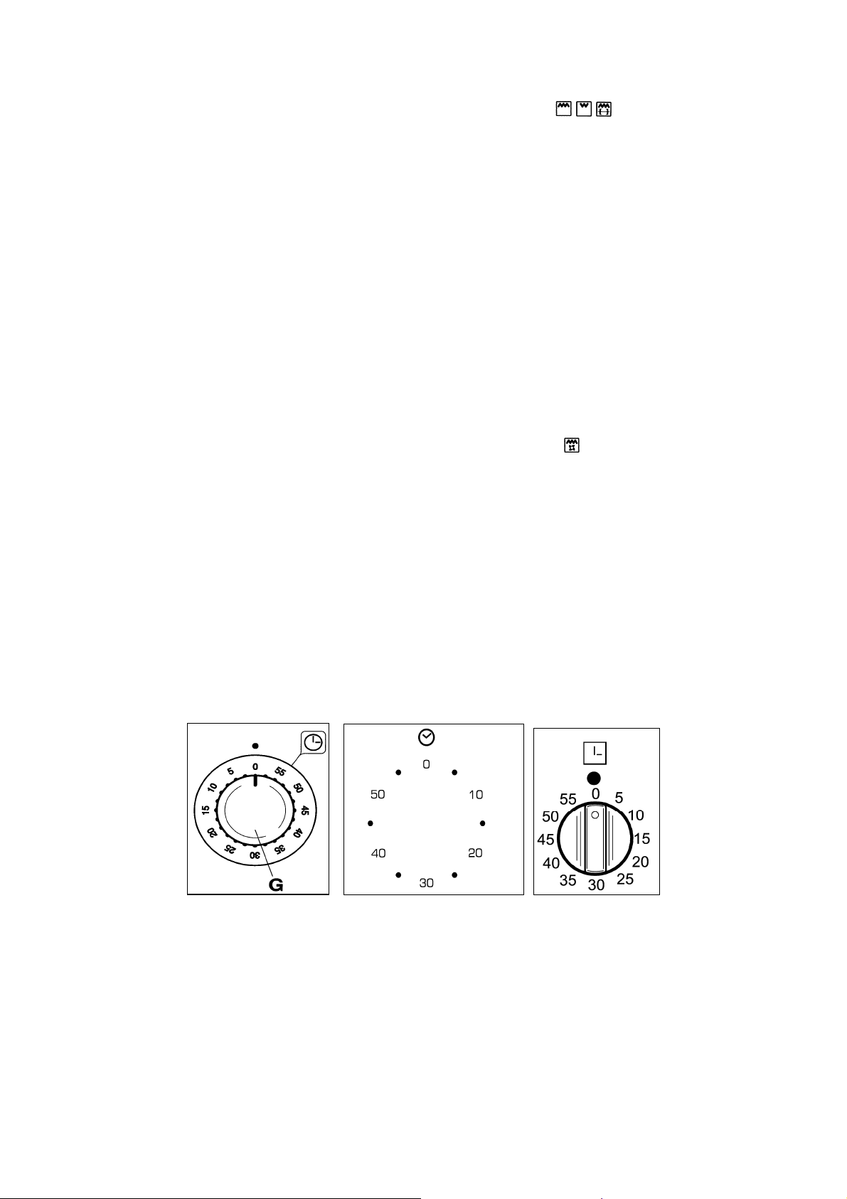
USING THE MINUTE-MINDER (Fig.37A-37B-37C)
The minute-minder advises the user, with an acoustic signal, when food has bee n cooke d, after a certain time per iod ha s
elapsed. To use the device, wind the minute-minder by turning the knob clockwise one complete turn. Then turn the knob
counterclockwise so that the indicator corresponds with the selected cooking time.
WARNING: The acoustic signal does not stop the cooking cycle. The u ser must turn off the cookin g cycle by
hand using the relative knobs.
Fig. 37A Fig. 37B Fig. 37C
28
Page 29
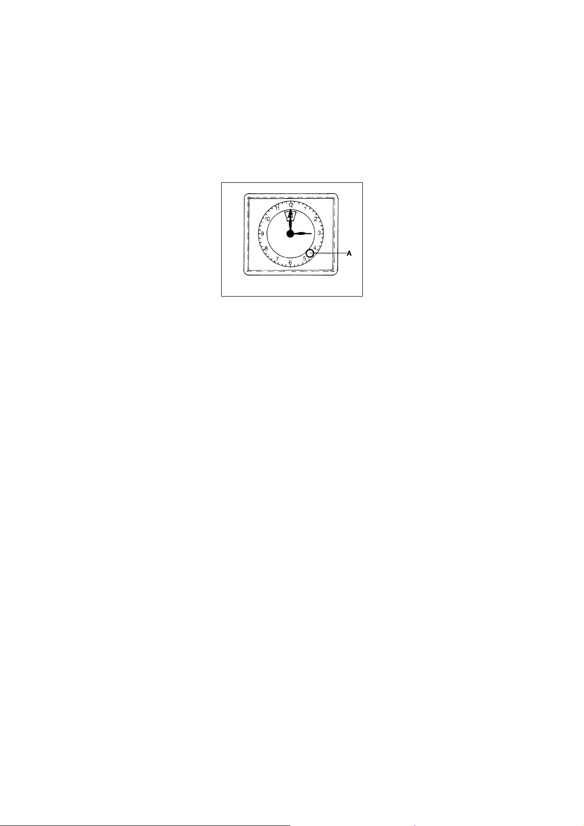
ANALOGUE CLOCK WITH TIMER (Fig. 38)
The analogue clock with timer lets you know when the cooking is finished thanks to an acoustic signal.
To set the clock, push and turn the pivot clockwise until you reach the chosen time; release the pivot, then turn it
clockwise again (without pushing) until the ring is positioned on the crossed bell: in this way only the clock will be
functioning.
To use the timer, turn the pivot clockwise without pushing and choose, using the ring, the cooking time; once the time i s
over the clock will alert you with an acoustic signal.
PLEASE NOTE that the acoustic signal does not interrupt the cooking process. To stop it, it is necessary to
switch off manually with the corresponding buttons.
Fig.38
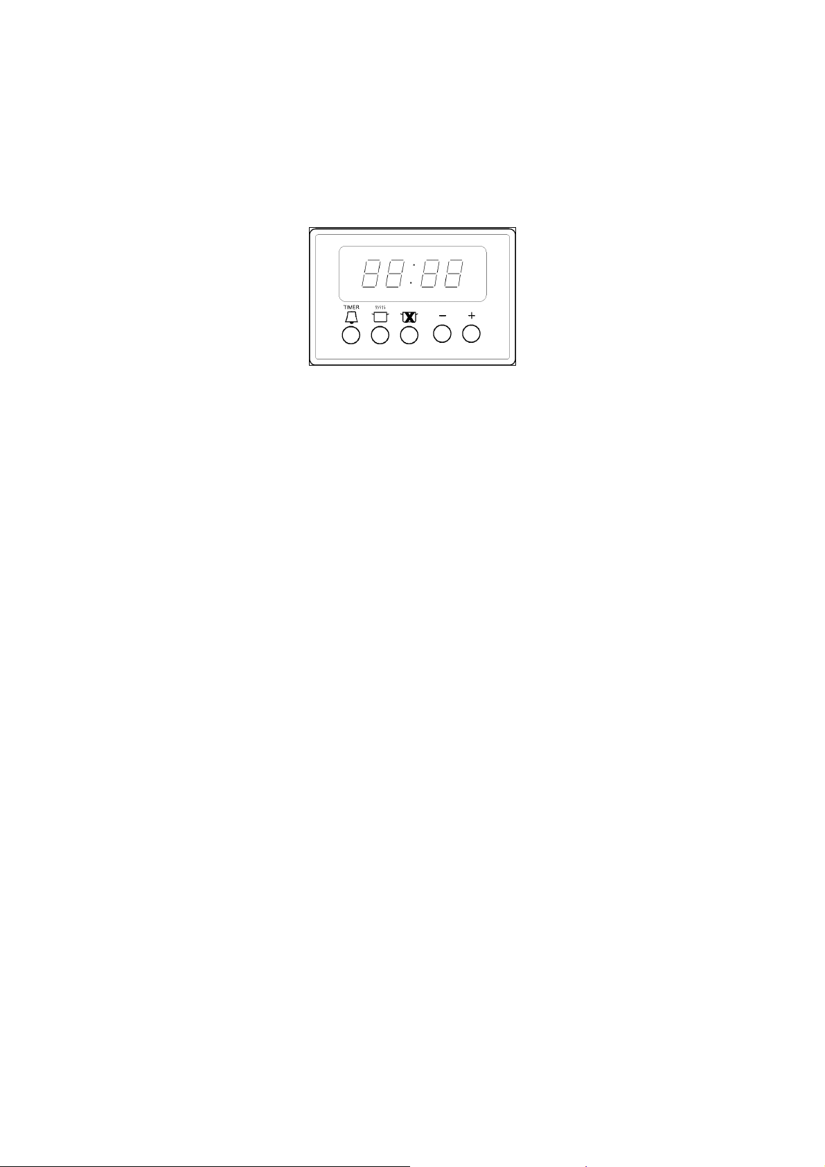
ELECTRONIC TIMER (Fig. 39)
Setting
Select a function by pressing the function button and set the required time with the +/- buttons.
+/- buttons
Pressing the “+” button increases the time set, pressing “-“ decreases it. The count-up and count down speed increases
the longer the button is held in the appropriate position
Setting the time of day
Select the time of day function by pressing the duration an d end time butt on together an d set the time of day with the +/-
buttons.
Any programme which has been set is cancelled and the outputs switched on
Manual operation
Press duration and end time button together. The relay contacts will switch on. The “A” symbol will be erased, the pot
symbol illuminated. Any programme which has been set is cancelled.
Semi-automatic operation with cooking duration
Select the cooking duration function and set the required duration with +/- button. “A” and cookpot symbol appe ar. The
relay output becomes active. If time of day = cooking end time the relay output and the cookpot symbol are switched off.
The audible signal sounds. The symbol “A” blinks.
Semi-automatic operation with cooking end time
Select the cooking end time function and set the required duration with +/- button. “A” and cookpot symbol will appear.
The relay output becomes active. If time of day = cooking end time the r ela y out put a nd t he co okpot s ymbol are switched
off.
The audible signal sounds and “A” blinks.
Fully automatic operation
Select the cooking duration function and set the requir ed duration with +/- button. The “ A” symbol appears. The relay is
switched on and the cookpot symbol appears. Select the cooking end tim e function and the earliest p ossible end time is
displayed. Set the required end time with the +/- buttons. The relay and the cookpot symbol are switched off.
The cookpot symbol appears again when time of day = the calculated start time.
After the automatic programme has ended, the symbol “A” blinks.
The audible signal is heard and the cook pot symbol and the relay are switched off.
Minute minder
Select the minute minder button and set required time with the +/- butto ns. As the time set elapses the bell symbol is
displayed. After the time set has elapsed, the audible signal sounds.
Audible signal
The audible signal sounds at the end of a minute m inder cycle or of a cooking prog ramme for a period of 7 minutes. T he
signal can be cancelled by pressing any function button. Pr essing the “-“ button without having previously selected a
function the frequency of the signal changes. A selection from 3 possibiliti es can be mad e. The selecte d signal is au dible
as long as the time the “-“button is pressed.
Programme start and verification
A programme which has been set is carried out after setting the time required. The “time to run” can be verified at an y
time by selecting the appropriate function.
29
Page 30
Setting error identification
The setting is correct if the time of day is in between the calculated cooking start and end times. If an error has been
made, this will be indicated by the audible signal and by the symbol “A” flashing. The faulty setting can be corrected b y
changing one or both functions.
Cancelling programme
A programme can be cancelled by selecting the manual func tion. After a programme which has been set comes to an
end, it is automatically cancelled.
Fig. 39
CLEANING THE APPLIANCE
Before cleaning the appliance, it should be disconnected from the power supply and turn off the main gas
feeder valve.
Cleaning the work surface
Periodically clean the burner heads, the enamelled steel gr ids, the enamelled covers and the flame caps using warm
soapy water. Then those parts should be rinsed and thoro ughly dried.
Any liquid that overflows from pots must always be removed using a rag.
If it becomes difficult to open or close a valve, do not force it, but immediately request the assistance of the
technical service personnel.
Cleaning the enamelled parts
To maintain the original features of the enamelled parts they shoul d be cleaned frequently with soapy water. Never use
abrasive powders. Do not leave acidic or alk aline substances on the enamelle d parts (vinegar, lemon juice, salt, tomato
sauce, etc.) and do not wash the enamelled parts while they are still hot.
Cleaning the STAINLESS steel parts
Clean the parts with soapy water and then dry them with a soft cloth. The shine is maintained by periodically using
special products that generally are found in the market. Never use abrasive powders.
Cleaning the burner flame caps
Since the flame caps are resting on the bur ner, to clean them just remove them from their seat and wash them with
soapy water. After they have been thoroughly dried an d having checked that the holes are not clogged, they can be
replaced in their proper position.
Cleaning the inside of the oven glass
One of the features of the oven is the possibility of removing the interior glass simpl y by loosening the 2 screws B (Fig.
41), to clean the inside surface of the glass (Fig. 40). This operati on s hould be carri ed ou t while the oven is c old an d with
a damp cloth. Do not use abrasives.
Cleaning the inside of the oven
To thoroughly clean the inside of the oven, it is recommended to disassemble the door by carefully following the
instructions described below. Insert the hook C into the hinged sector D. Put the door in a semi-open position and usin g
both hands pull it towards you until it is relea sed from the attachment. To repl ace the door, do the oppos ite making sure
to insert the two sectors F correctly. In addition, the side shelves can be remove d very e asily, by loose ning the lock r ings
that attach them to the oven.
30
Page 31
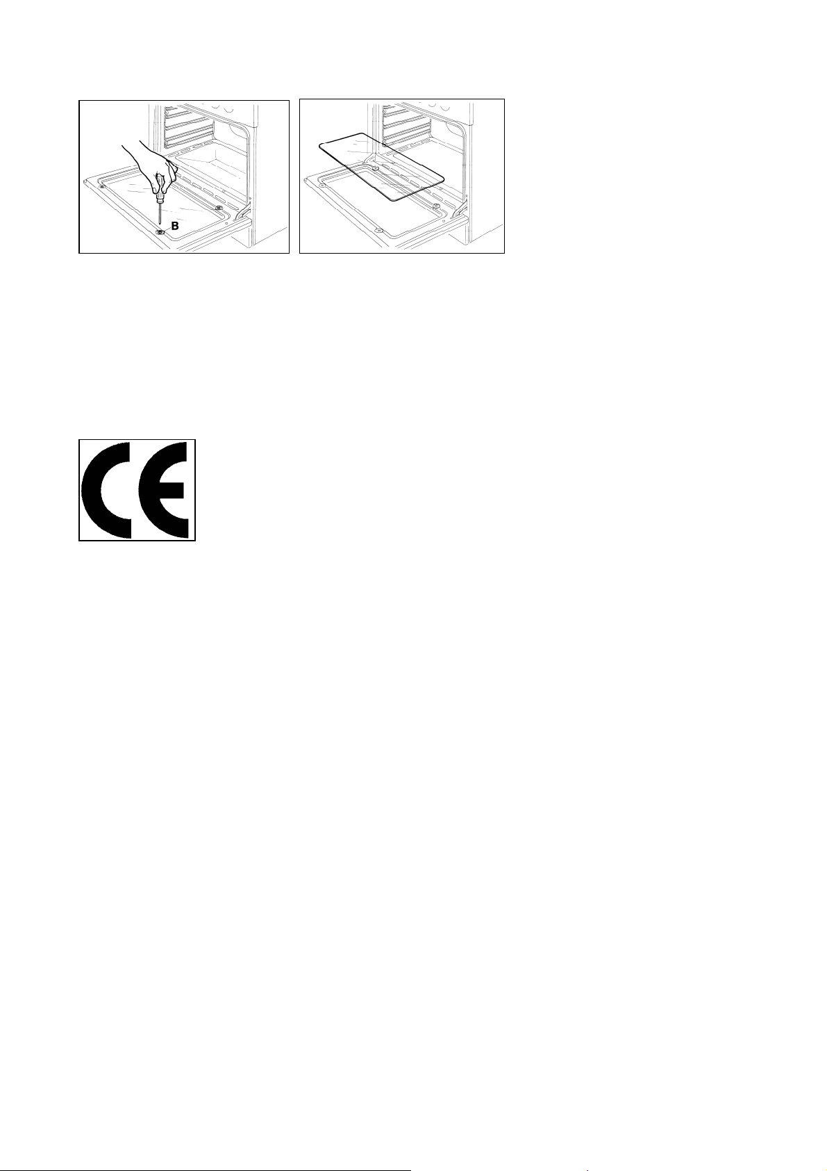
Fig.41 Fig. 40
AFTER-SALES TECHNICAL SERVICE AND SPARE PARTS
Before leaving the factory, this appliance was tested and calibrated by skilled and qua lified personnel.
Any repairs or calibration that may become necessary after leaving the factory should b e performed b y skilled pers onnel.
For this reason we advise the customer to contact the Retailer that sold the applia nce or the Customer Care Team on
1800 444 357, providing them with information about the type of appliance and the t ype of problem that has occurred. If
defective parts must be replaced, it is recommended to replace them with orig inal spare parts that are available from
Pronto Parts (1300 306 973) and authorised dealers.
310223
31
 Loading...