

Venini VEF61.1GG Installation Instructions User Instructions

INSTALLATION INSTRUCTIONS
USER INSTRUCTIONS
COOKER MODEL
F61GG
60X60 cm

Dear Customer,
Congratulations on purchasing your new product from Think Appliances.
To register your parts and labour warranty (some conditions apply please refer to your
warranty card for more details) please contact out Customer Care team on:
1800 444 357
Our Customer Care centre is there to ensure you get the most out of your appliance. For
example, should you want to learn more about recommended cooking temperatures, the
various cooking functions available, how to set and program your LED clock, and importantly
taking care of your appliance when cleaning, please call us because we are here to help you.
It is important that you read through the following use and care manual thoroughly to
familiarize yourself with the installation and operation requirements of your appliance to
ensure optimum performance.
We also carry a complete range of spare parts for all Think products. For all your spare parts
enquiries please contact our team at Pronto Parts on:
1300 306 973
Again, thank you for choosing an appliance brought to you by Think Appliances and we look
forward to being of service to you.
Kind regards
Management
Think Appliances

Important information
Introducing your new cooker
We thank you and congratulate you on your choice.
These carefully designed products, manufactured with the highest quality materials, have
been carefully tested to satisfy all your cooking demands.
We therefore request that you read and follow these easy instructions which will allow you
to obtain excellent results right from the start.
AlI cookers feature a gas hotplate containing 4 cooktop burners, including one wok burner
positioned at the left, electronic ignition to all burners, and a minute minder. The fan gas
oven is fitted with an electric grill element positioned against the roof of the oven and self
cleaning oven linings.
The cooker's data plate is accessible even with the cooker fully installed. It is positioned
on the inside of the oven door, centre bottom.
Always quote the details from it to identify the appliance when ordering spare parts or
requesting a service call.
Notes on disposal
Old appliances still have some residual value. An environmentally friendly method of
disposal will ensure that valuable raw materials can be recovered and used again.
Before you dispose of your old appliance, make sure that it has been rendered inoperable.
Your new cooker was protected by suitable packaging while it was on its way to you. All
materials used for this purpose
are environmentally friendly and suitable for recycling.
Please make a contribution to protecting the environment by disposing of the packaging
appropriately.
Do not spray aerosols in proximity of this appliance while it is in operation.
Where this appliance is installed in a marine environment or in caravans,
for safety reasons it should not be used as a space heater.
This appliance is unsuitable for installation in marine crafts, caravans or
mobile homes, unless each burner is fitted with a flame safeguard.
DO NOT MODIFY THIS APPLIANCE.
DO NOT USE OR STORE FLAMMABLE MATERIALS NEAR THIS APPLIANCE.
This appliance is not intended for use by persons (including children) with
reduced physical, sensory or mental capabilities, or lack of experience and
knowledge, unless they have been given supervision or instruction
concerning use of the appliance by a person responsible for their safety.
Children should be supervised to ensure that they do not play with the
appliance.
Warning: Accessible parts will become hot when in use. To avoid burns or
scalds children should be kept away.
Warning: In order to prevent accidental tipping of the appliance, for
example by a child climbing onto the oven door, the stabilising means

must be installed. Refer to the instructions for installation.
Before connecting your new cooker
Before using your new cooker, please read these 'Instructions for Use' carefully. They
contain important information concerning your personal safety as well as on use and care
of the oven.
Please keep the operating and installation instructions in a safe place; this important
documentation may also be of use to a possible subsequent owner.
Do not use the cooker if it is damaged in any way.
Installation and connection of the cooker should be performed according to the
instructions and connection diagram provided, and should be entrusted to a licensed
specialist. In the event of damage that occurs as a result of improper connection, the
warranty will be void.
Our appliances meet the applicable safety regulations for electrical appliances. Repairs
may be performed only by authorised persons. Inexpert repairs may cause serious injury to
you, the user.
Safety considerations
Never leave the appliance unattended when cooking with fat or oil. It could ignite if
overheated.
In case of a defect, switch off at the mains.
Do not clean the oven with steam or high pressure cleaners.
Ensure that the power cord does not get caught in the hot oven door. The plastic
insulation could melt.
Do not use loose greaseproof paper in the oven (e.g. when heating the oven). The paper
could be drawn to the fan and damage the fan and the element.
Do not insert a baking sheet or aluminium foil sheet at the bottom of the oven. A heat
build-up could result and cooking times and temperatures could change or enamel could
be damaged.
Do not pour water on the hot oven floor. Damage to enamel could result.
Always place a baking tray below a roast to prevent juices from dripping on the oven lining.
Do not place heavy items on the oven door when open as this may result in damage to the
door hinges.
To ensure correct cooking the oven door must be closed properly.
Keep the door sealing surfaces clean at all times.
Installation instructions
Statutory regulations
This appliance should be installed in accordance with the manufacturer's installation
instructions, local gas fitting regulations, municipal building codes, electrical wiring
regulations, AS 5601 the Australian Standard for gas installations. Refer also to AS 5601
for pipe sizing tables.
Gas supply
Check that the data plate shows the appliance is suitable for the available gas supply. The
data plate is located on the inside of the oven door, centre bottom.

Electrical supply
The cooker requires connection to a 10 Amp wall socket.
Instructions
1. The model number and the type of appliance, gas pressure and gas type are found on
the inside of the oven door, centre bottom.
2. The appliance requires connection to a 240 V,50 Hz electric supply. The power point
must be installed by an authorized person.
3. Before commencing any work, make sure that the power point switches are turned off
and the three pin plug is removed.
4. If the appliance cannot be adjusted to perform correctly contact your local gas utility.
5. Instruct the user in the operation of the appliance before leaving.
Vertical clearances:
The cooker should be installed so that a vertical clearance of at least 600 mm is maintained
between its burners and any combustible material, and where this is not practical, the
underside of any combustible material less than 600 mm above the burner should be
protected by noncombustible millboard at least 6 mm thick which is covered with sheet
metal not less than 0.4 mm thick, or should be protected by an equivalent material,
extending at least 225 mm beyond the sides of the cooker.
Overhead clearances:
Range hoods and exhaust fans should be installed in accordance with the manufacturer's
instructions. However, in no case should the clearance between the top of the highest burner
of the cooking appliance and the underside of a range hood be less than 600mm, or an
overhead exhaust fan, 750 mm.
Side clearances
to vertical surface:
If the distance measured from the periphery of the nearest burner to any vertical
combustible surface, is less than 200 mm, the surface should be protected in accordance
with clause 5.12.1.1 and 5.12.1.2 of A5 5601.
Installation
Make sure the minimum clearances to combustible materials are maintained during the
installation including adequate space for the operation and servicing of the cooker. For
height limitations use the dimensions as shown in the drawing.
Overall dimensions (with legs adjusted to 180mm).
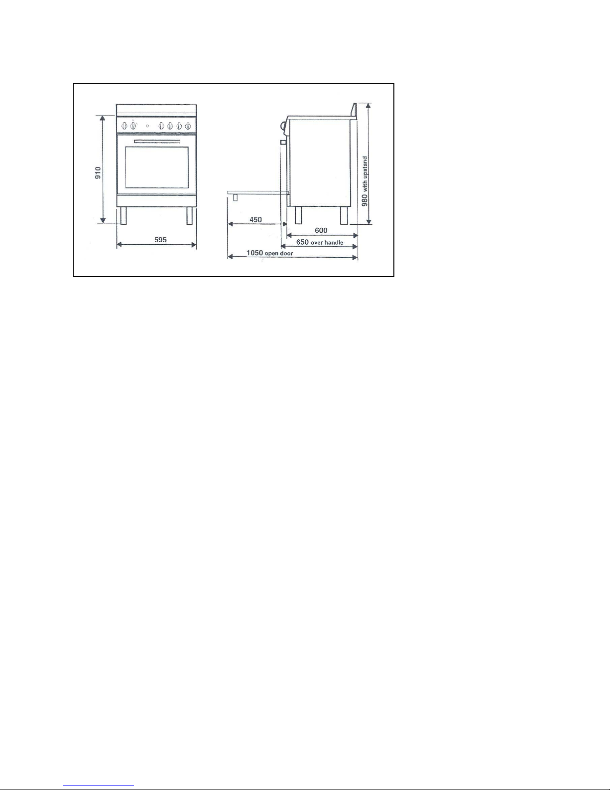
Height over hob: 910 mm
Height over upstand: 980 mm
Width: 595mm
Depth: (incl. oven door handle & knobs): 650mm
Depth: (flush with oven door): 600mm
Gas and electric connection
Electrical connection
The electric lead and plug are for connection to a 10 Amp socket. A 10 Amp
socket is to be within 1 m of the appliance.The lead is situated at the left hand side
of the cooker.
Gas regulator
The gas connection is via 1/2" compression. Connect the cooker to the gas supply
and check for gas soundness.
If using a flexible connection
This appliance is approved for connection with a Flexible Hose, which complies with
AS/NZS 1869 (AGA Approved), 10mm ID, class B or D, between 1 - 1.2m long .
Connection shall be in compliance with AS 5601, clause 5.12.1.8.
When installing the hose restraint device, the appliance anchor point is the rear panel
securing.
If using copper connection

To allow the cooker to be moved forward for service make a loop in the copper tube
before connecting onto the regulator.
Gas connection
The cooker must be connected to the gas supply with upstream connection of an
isolation valve in accordance with the respectively valid regulations. We
recommend that the isolation valve be fitted prior to the cooker to enable isolation
of the cooker from the gas supply. The valve must be easily accessable at all times.
To find out the factory set gps type, see the label at the rear of cooker.
The gas connection is via 1/2" compression. Connect the cooker to the gas supply
and check for gas soundness. NEVER use a naked flame to check for gas leaks.
Gas inlet (mm)- Nat gas Gas inlet (mm)- LPG
From RH rear side: 35 mm From RH rear side: 35mm
Up from floor: 590 mm Up from floor: 675 mm
Gas inlet with different leg heights – mm
Min NG: 560 LP: 645
Ref NG: 590 LP: 675
Max NG: 595 LP: 680
Energy consumption
Burners Gas type
Pressure (kPa)
Injector (mm) Mj/hr Watts
Small Natural 1.0 0.90 4.00
U-LPG 2.75 0.54 3.75
Medium Natural 1.0 1.18 7.10
U-LPG 2.75 0.70 6.20
Wok Natural 1.0 1.55 12.0
U-LPG 2.75 0.93 11.5
Oven Natural 1.0 1.50 11.0
U-LPG 2.75 0.85 9.40
Grill 2000 W
Test the operation of the cooker before leaving
Note: These burners have no aeration adjustment.
Check correct operation of the ignitions system and operation of burners individually and in
combination. Burner flames should be clear blue, with no yellow tipping. If the burners
show any abnormality check that the burners are correctly located. If satisfactory
performance can not be obtained, contact the local gas utility.
Important
Before leaving instruct the owner in the use of the cooker. It should be expressly noted that
we cannot accept any liability for direct or indirect damage caused by wrong connection or
improper installation. When being repaired, the appliance must always be disconnected
from the mains supply; if required, notify our customer service.
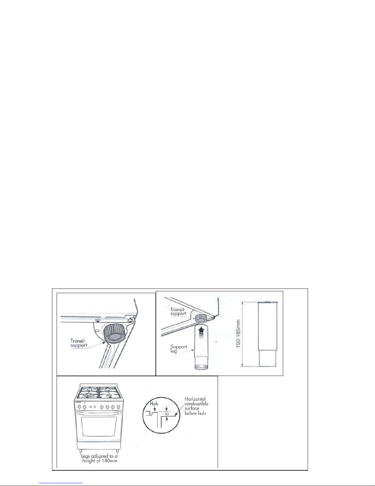
Support legs
The cookers are supplied with four transit supports.(One for each corner).
4 support legs are supplied separately and are fitted on location to the four corners
of the lower support frame. Each support leg is pushed over the relevant transit
support until flush with the support frame.
Each leg is adjusted by screwing the lower section in or out as required for fitting to a
900mm bench height. For lower bench tops adjust the height as required.The adjustment
range for the leg is 150-185mm. With the legs adjusted to a height of 180mm the hob is
located 10mm above the horizontal combustable surface, ref. AS5601.
 Loading...