

Page 1
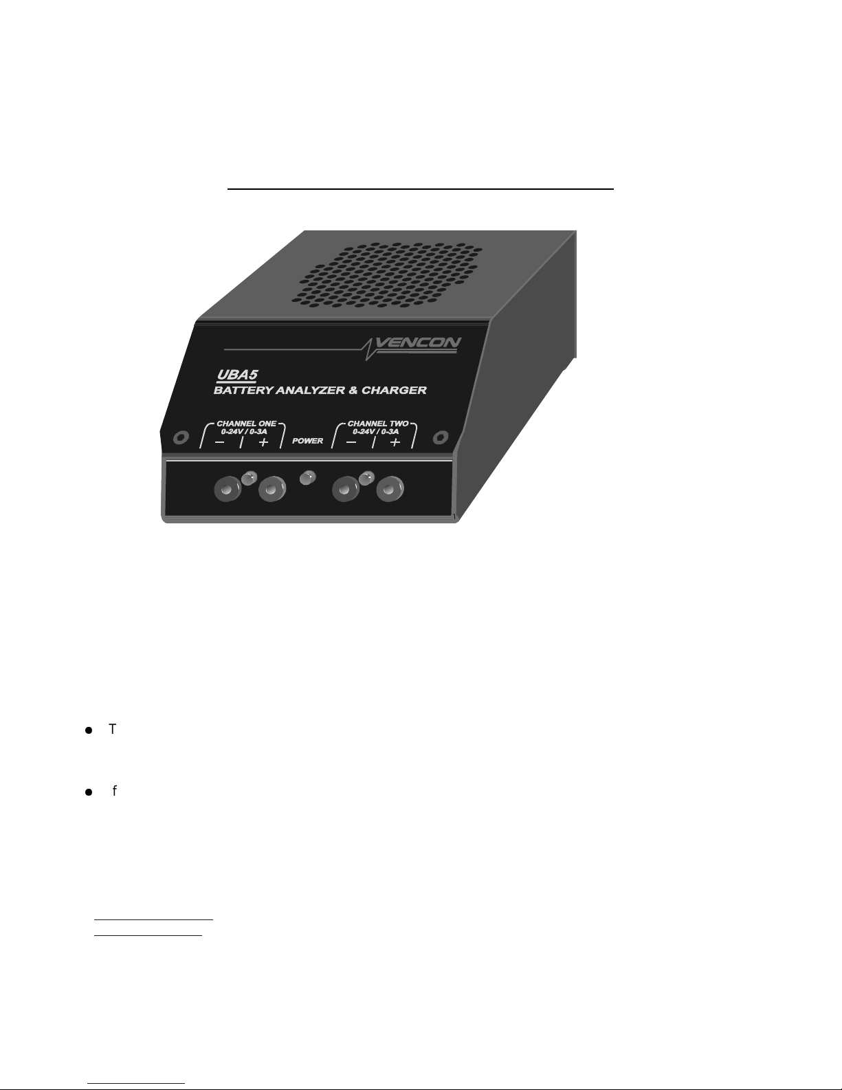
The UBA (Ultimate Battery Analyzer) is a battery analyzer, charger, discharger and reconditioner. It’s also a data
logger, thermometer and electronic load . Wow! That’s a lot of stuff in such a small box. How do we do it? Easy. We
get the PC to do most of the work.
The first three chapters in this guide show you how to setup the UBA then takes you step by step through a complete
battery analysis. Once you’ve done your first battery analysis, you can use the online help that comes with the UBA
Software to learn more. We recommend that you read these first three chapters before you run your first battery
analysis (it won’t take that long).
Notes:
●
The latest version of software and online help is available at the private area of our web site. To get there, run
UBA Console and click on Get latest news on Vencon Website (Help menu), or go to:
http://www.vencon.com/UBA4News/B-0.96.html, or use the shortc ut on the installation CD.
●
If you need help using the software or testing batteries, don’t hesitate to call or email us. You can also email
us your battery analysis results for assistance in interpreting them.
Printed September 2007 for UBA Console version 1.0.
The UBA Let's Get Started Guide Page i
Page 2
Batteries are electro-chemical devices that have the potential to burn, explode, or emit harmful chemicals.
Please read these safety warning s:
Safety Warnings:
●
Observe battery temperature. Allow cold batteries to warm up and hot batteries to cool
before charging. Stop the battery test if the battery becomes very hot.
●
Do not attempt to charge non-rechargeable batteries such as alkaline, carbon-zinc,
or non-rechargeable lithium batteries. Attempting to charge them may result in explosion.
●
Do not short the positive and negative battery terminals together.
●
Do not exceed the battery manufacturer’s recommended charge current and voltage limits.
Doing so may damage the battery and result in venting or explosion.
●
Charge and discharge lithium batteries in a fire proof container.
●
Double check the settings before starting a battery analysis.
Page ii The UBA Let's Get Started Guide
Page 3

Table of Contents
1.Setting Up The UBA.........................................................................................................................................................1
1.1.Connecting the UBA to a Power Supply..................................................................................................................1
1.2.Connecting the UBA to a Computer........................................................................................................................2
1.3.Connecting More than One UBA to a Computer.....................................................................................................2
1.4.Extending the Serial Cable......................................................................................................................................2
1.5.Ventilation................................................................................................................................................................3
1.6.Battery Cables..........................................................................................................................................................3
2.UBA Console Installat ion instr uctions..............................................................................................................................4
2.1.Installing UBA Console............................................................................................................................................4
2.2.Starting UBA Console..............................................................................................................................................5
2.3.Initializing the UBAs.................................................................................................................................................5
2.4.Locating and Installing the UBA Calibration File(s).................................................................................................6
3.Is My Battery any Good? The Battery Analysis...............................................................................................................6
3.1.The Multitester.........................................................................................................................................................6
3.2.Setting Up the Bat tery Anal ysis...............................................................................................................................7
3.3.Starting the Battery Analysis..................................................................................................................................10
3.4.Monitoring the Battery Analysis.............................................................................................................................11
3.5.Interpreting the Results – Is My Battery Any Good?.............................................................................................11
4.Creating a Battery Analysis Routine.......................................................................................... ....................................13
4.1.“Advanced” BAR Concepts....................................................................................................................................17
4.2.BAR Actions...........................................................................................................................................................19
4.3.BARs Included with UBA Console.........................................................................................................................19
5.Advanced Topics............................................................................................................................................................20
5.1.Choosing and Setting Up a Power Supply.............................................................................................................20
5.2.Importing Results into a Spreadsheet...................................................................................................................22
5.3.Warnings................................................................................................................................................................22
5.4.Current and Power Limitations..............................................................................................................................23
Appendix A – Troubleshooting..........................................................................................................................................24
Appendix B – FAQs...........................................................................................................................................................25
Appendix C – Included Battery Analysis Routines............................................................................................................27
UBA Accessories – Optional Temperature Probes...........................................................................................................29
UBA Accessories - Channel Combiner.............................................................................................................................33
UBA5 Specifications..........................................................................................................................................................35
Two Year Limited Warranty...............................................................................................................................................35
The UBA4 Let's Get Started Guide Page iii
Page 4

Regulatory Compliance
FCC Class B Information
This equipment has been tested and found to comply with the limits for a Class B digital device, pursuant to Part 15 of
FCC Rules. These limits are designed to provide reasonable protection against harmful interference in a residential or
commercial installation. This equipment generates, uses and can radiate radio frequency energy and, if not installed
and used in accordance with the instructions, may cause harmful interference to radio or television reception, which
can be determined by turning the equipment off and on, the user is encouraged to try to correct the interference by one
or more of the following measures:
●
Reorient or relocate the receiving antenna.
●
Increase the separation between the equipment and receiver.
●
Connect the equipment into an outlet on a circuit different from that to which the receiver in connected.
●
Consult the dealer or an experienced radio/TV technician for help.
CE Compliance for Europe
This equipment has been verified to comply with
CISPR22/EN55022 - Class B - Limits and methods of measurements of radio disturbance characteristics of
Information Technology Equipment and
EN50082-1 - Generic Immunity Standards, Residential, Commercial and Light Industry.
The UBA Let's Get Started Guide Page v
Page 5

1. Setting Up The UBA
●
Unpack the UBA shipping box and check that you’ve received the following:
●
The UBA battery analyzer, charger, and conditioner.
●
Vencon UBA Console CD, which contains the software for the UBA.
●
A 2 metre 9 pin male to female shielded serial cable.
●
Two sets of test leads with alligator clips.
●
A printed copy of this guide.
●
A power supply (if you purchased a UBA Combo).
What you need to get started (in addition to the above):
●
A power supply (included with the UBA Combo).
●
A PC with a free serial port or a USB port and a USB to serial converter.
1.1. Connecting the UBA to a Power Supply
The UBA requires a power supply with a DC voltage from 15 to 24V (see section 5.1 “Choosing and Setting Up a
Power Supply” for more information). Connect the power supply output cable to the back of the UBA and plug the
power supply’s AC cable into a wall outlet. The battery red LEDs will flash once, the fan will spin a couple of times and
the power LED will turn on. If this doesn’t happen then check the voltage on the power cable: it should be at least 15V
with the centre pin positive.
If you use your own power supply ensure that it has a 2.1mm DC barrel plug that mates with the power input on the
back of the UBA. The UBA is reverse voltage protected, if you reverse wire the DC supply cable no damage will result,
but the UBA won't turn on. Also ensure that the power supply voltage is no more than 25V no-load, otherwise you risk
damaging the UBA.
The UBA Let's Get Started Guide Page 1
Page 6
1.2. Connecting the UBA to a Computer
UBA
Vencon
To Additional
USB Converter
Serial cable
(1 per UBA)
USB
Port
Serial
Port
UBAs
PC
Vencon
UBA
First UBA
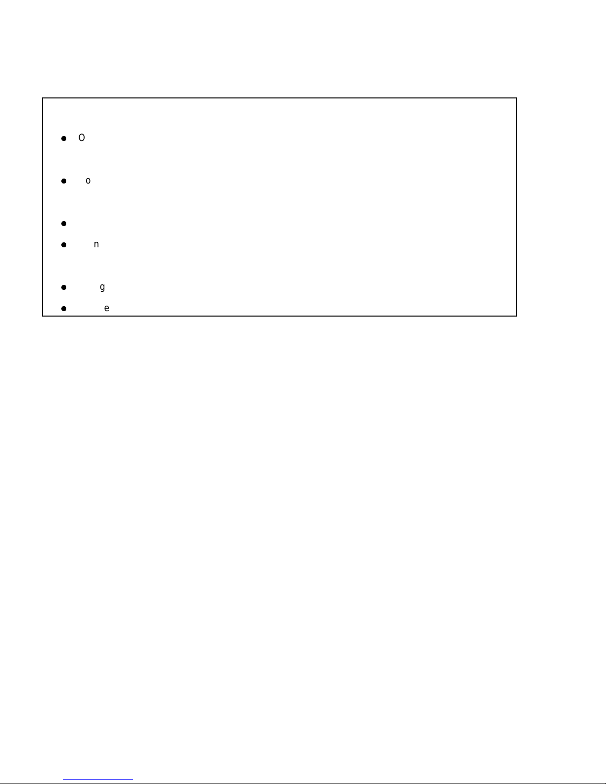
Figure 1: UBA serial port connections for one or more UBAs.
The UBA connects to any unused serial port the PC. You can use a USB port with a USB to serial port converter contact us for purchase information. Connect one end of the supplied serial cable to the UBA (the connector marked
“RS232 from Computer or other UBA”) and the other end to the PC serial port or USB converter.
Second UBA
1.3. Connecting More than One UBA to a Computer
If you are using more than one UBA, then connect the first one to the PC as described above and the second UBA to
the first UBA. No adapters or gender changers are required. Repeat this for any additional UBAs (the maximum is
253 UBAs per serial port, but performance and memory limits are reached before that). Each UBA requires its own
power supply or they can share a single power supply with enough current to power them all. You can connect the
UBAs while they are on, but you will have to re-initialize the UBA network for any new UBAs to be recognized.
1.4. Extending the Serial Cable
You can extend the UBA's serial cable with a shielded extension cable. We have successfully run the UBA with a 30m
(100ft) cable. Check for resent commands in the communication port display (accessible from the UBA Network
window by right clicking on the comm port). You really shouldn't have any, but if you do, don't worry as the UBA uses
advanced error correction so that any corrupted transmissions are resent.
Figure 2: Communication port display showing UBAs connected and the number of commands sent and resent
(commands are resent if there is a communication error). Here 21 million commands were sent without error.
This is an actual image from our burn-in station where UBAs are run for at least 12 hours.
Page 2 The UBA Let's Get Started Guide
Page 7
1.5. Ventilation
Battery
The UBA can generate up to 90 Watts of heat during a battery discharge or charge. Do not obstruct the air holes on
the top or bottom. Be careful when touching the UBA during a high current discharge or charge, as it can get quite hot
(the fan automatically turns on when the UBA gets too warm). Avoid running a high power discharge or charge when
the UBA is in a hot environment (greater than 30 degrees Celsius).
It is normal for the UBA to get get warm (some might call it hot) before the fan turns on. You can check that the fan is
functioning by watching if it turns on when power is applied to the UBA or during network initialization or you can turn it
on from the Multitester instrument (described later). If you would prefer that the fan turn on earlier, there is an option
for this in the Options... menu (under File, click on Options... and select the General tab).
1.6. Battery Cables
-
+
Vencon
UBA
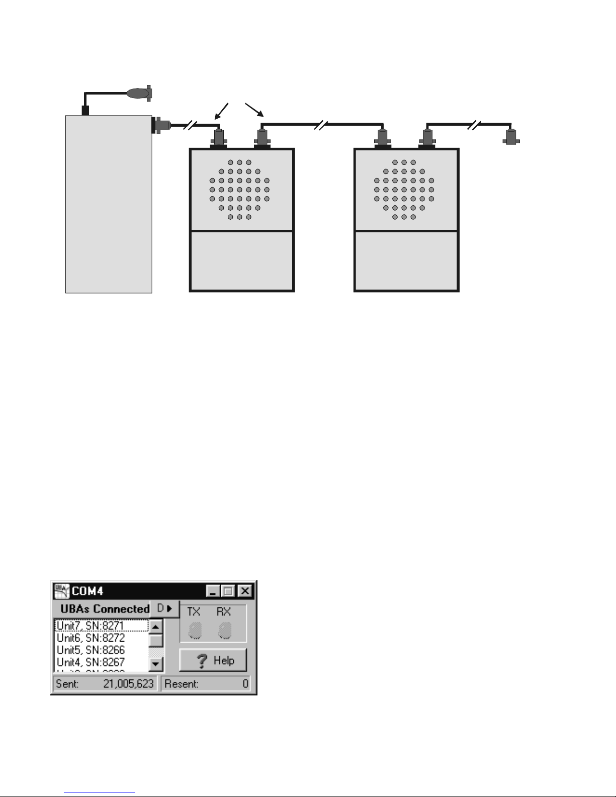
Figure 3: Connecting a battery to the UBA.
banana jacks for its battery connections and comes with two sets of battery cables with alligator clips. Additional plugs
or cables are available from us. Plug the cables into the front of the UBA and connect the red clip to the positive
terminal of the battery being tested and the black clip to the negative terminal of the battery.
NOTE: The UBA inputs are polarity protected, thus connecting the battery backwards will not damage your battery,
nor the UBA.
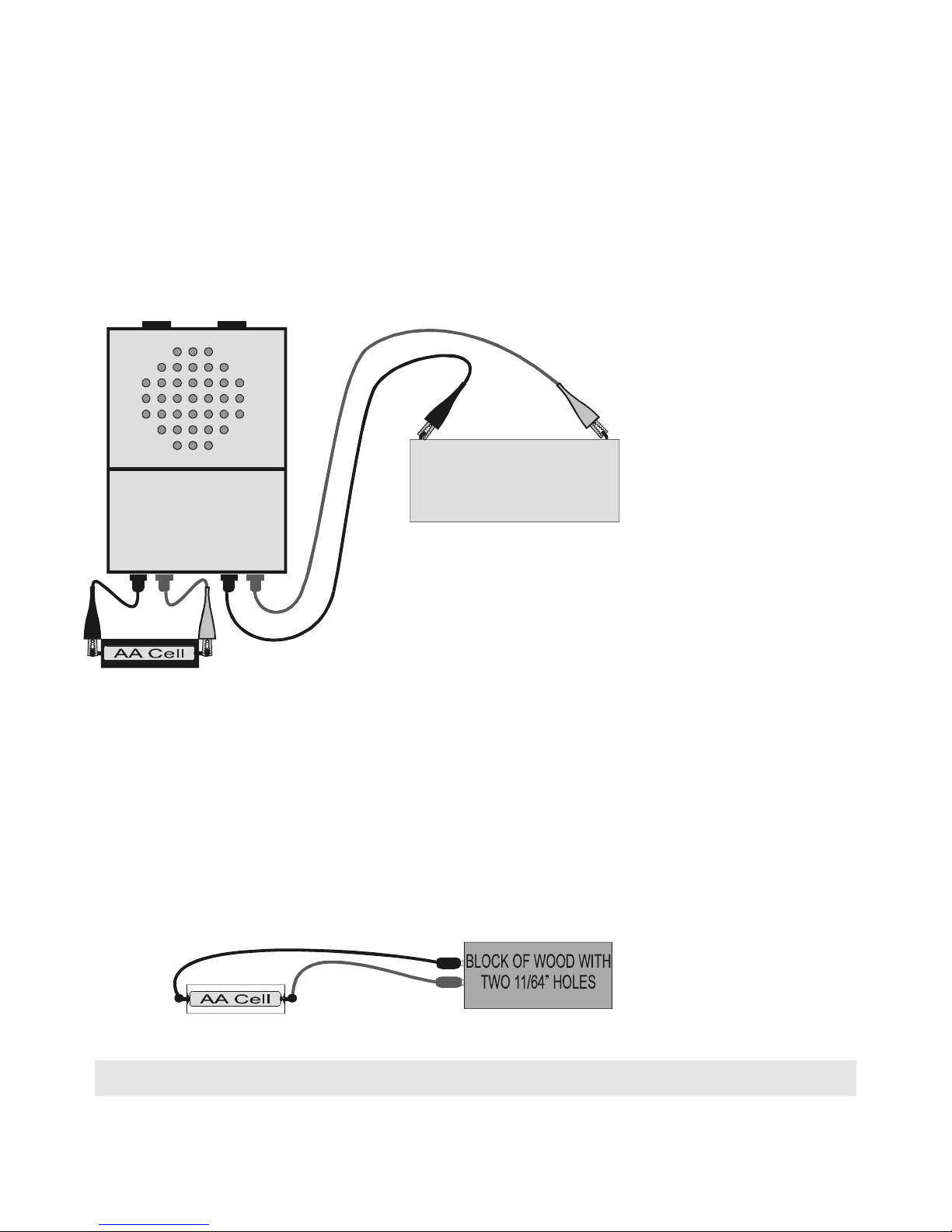
CAUTION: When the battery cables are connected to a battery but not plugged into the UBA, the banana plugs can
touch each other resulting in very high currents potentially causing burns or the battery might gas or explode. For this
reason, we recommend that the banana plugs be plugged into the UBA before connecting them to your battery. In our
lab banana plugs connected to a battery, when not connected to a UBA, are inserted into a piece of wood with 11/64”
(4.5mm) holes that keep the plugs safely apart.
The UBA uses standard
Figure 4: Using a block of wood to keep battery banana plugs from shorting.
Hint: If you expect to be testing cylindrical cells (like AA, AAA, C, ...) then consider using battery connectors
with magnets. Contact us for ordering information.
The UBA Let's Get Started Guide Page 3
Page 8
2. UBA Console Installation instructions
The software that runs on the PC and controls the UBA is called UBA Console. Install it on a PC running Microsoft
Windows (Win95 or later) or Linux (we have an application note on our website explaining how to do run UBA Console
under Wine).
Windows 95 and NT users: If you will be installing UBA Console on a PC with a fresh install of Windows 95
or NT then you might have to install the HTML help application and some other upgrades to your operating
system. See the troubleshooting section at the back of this guide.
2.1. Installing UBA Console
Insert the UBA CD into the PC’s CD drive. Installation should start automatically. If it doesn’t, run SETUP.EXE on the
CD. If you’re installing from a file that you downloaded from our website, then run that file.
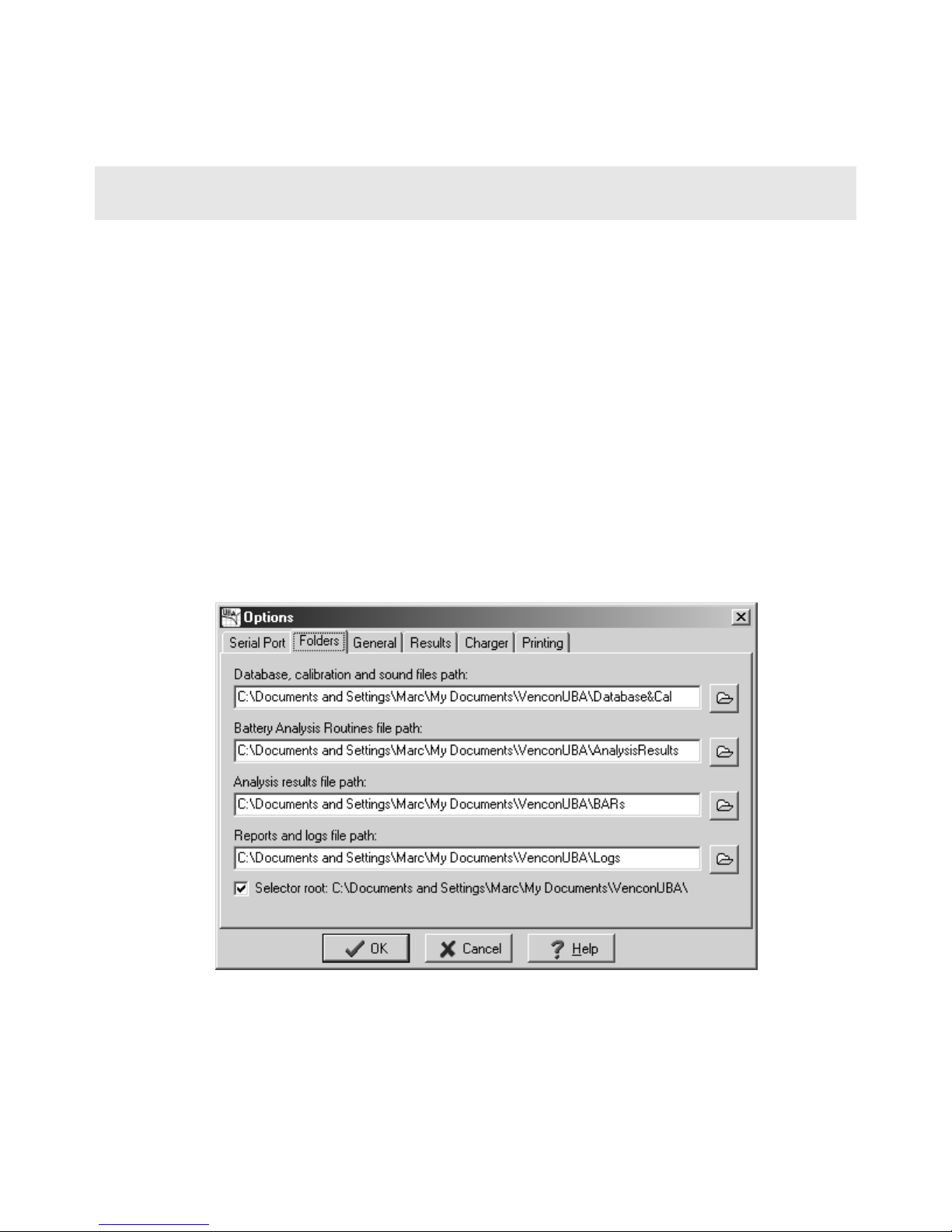
Important -- Data Location:
During the installation you will be asked where to locate the “application's database”. This folder, called VenconUBA,
is where the files containing battery analysis routines are stored as well as where the analysis results are stored. By
default it's put in the same folder as UBA Console, i.e.:
C:\Program Files\Vencon\Ve nco nUB A <- default (not recommended)
We recommend you choose a different location which is regularly backed up. For example on our PCs we put it in My
Documents:
C:\Documents and Settings\UserName\My Documents\VenconUBA <- recommended
You can change the folder location after UBA Console has been installed by moving (or dragging) the VenconUBA
folder to the new location then specifying it on the Folder tab in the Options dialog box (File menu).
Figure 5: Example folder paths.
The following four folders are created in the VenconUBA folder:
AnalysisResults – Analysis results are stored here.
BARs – Battery Analysis Routines are stored here.
Page 4 The UBA Let's Get Started Guide
Page 9
Database&Cal – Database, calibration, and sound files are stored here.
Logs – Log files are stored here.
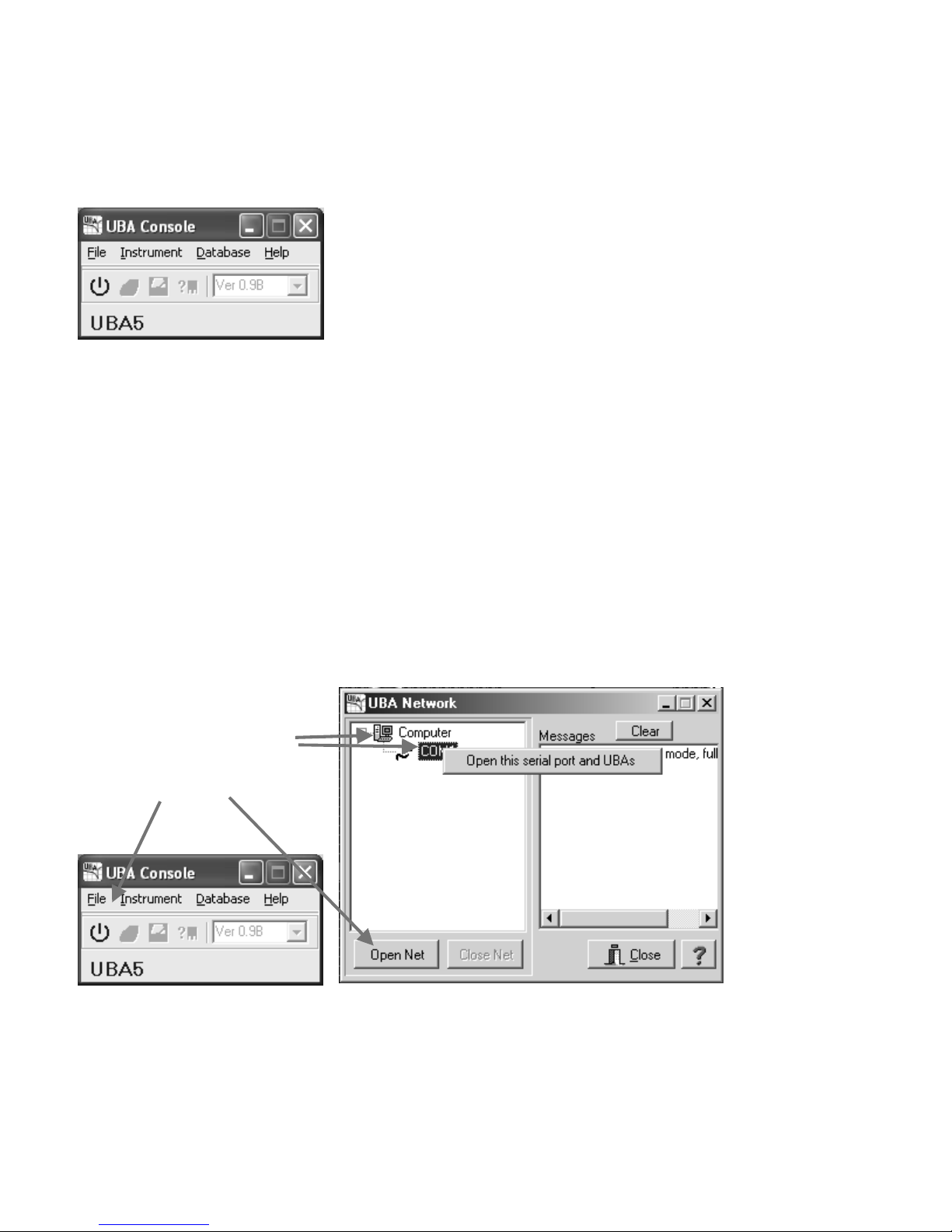
2.2. Starting UBA Console
Start UBA Console (accessible from the Windows Start menu).
Figure 6: UBA Console - UBA Network not yet initialized.
If you don’t get this, see Appendix A - Troubleshooting.
Don’t be surprised if your version of UBA Console appears slightly different then this as we’re always improving the
software.
2.3. Initializing the UBAs
UBA Console is now running, but its not yet communicating with the UBA. For that to happen, you have to initialize the
UBA Network. Tell the software which comm port(s) to use on the Serial Port tab in the Options dialog box (File
menu). Only free comm ports are displayed. You can choose more then one comm port, UBA Console will check
them all for a UBA each time you initialize the UBA network.
You can initialize the UBA Network by clicking on the first icon on the main menu (the “on/off” switch) or by the other
ways shown below.
Four ways to initialize the UBA
network:
Right click here or here.
or click here or here
Figure 7: Multiple ways to initialize the UBA Network.
Either way UBA Console will try to connect to the UBA using the serial ports that you have selected. You can close the
UBA Network window by clicking on the Close button or the X (this does not close the UBA network).
The UBA Let's Get Started Guide Page 5
Page 10
2.4. Locating and Installing the UBA Calibration File(s)
Every time UBA Console initializes a UBA Network, it reads the calibration file for each UBA that it detects. If it can’t
locate the calibration file in the VenconUBA\Database&Cal folder, it will put up a Calibration file not found dialog box.
Every UBA comes with a calibration file that can be found on the installation CD or it was emailed to you. Once
located, UBA Console copies it into the VenconUBA\Database&Cal folder so that it can find it next time.
Don’t lose the UBA’s calibration file, but if you do, don’t panic. We keep a copy. If you’ve made it so far you should
see this:
Figure 8: UBA Console with the UBA network initialized (icons are enabled).
UBA Console has now established communications with the UBA(s) and you can start any instrument.
3. Is My Battery any Good? The Battery Analysis
In this chapter, we're going for a quick tour of the UBA and to run a battery analysis. Start up UBA Console and
initialize the UBA Network.
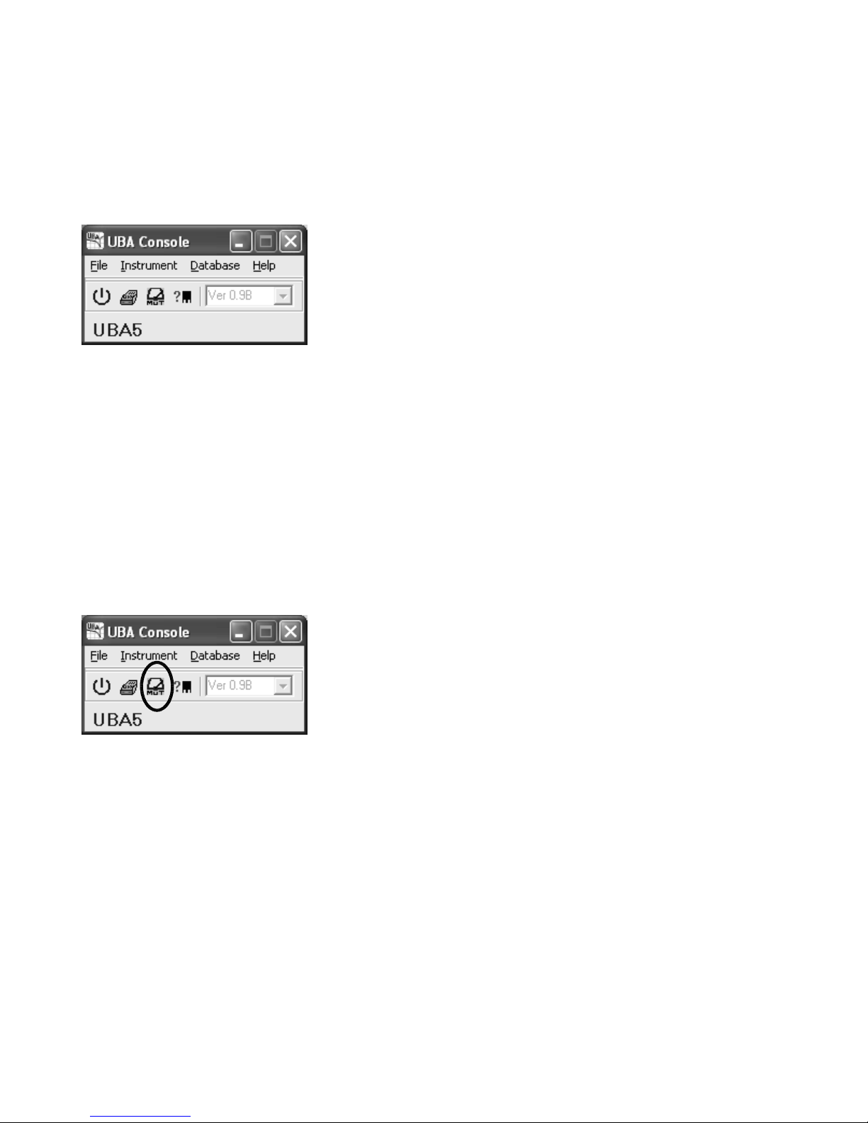
3.1. The Multitester
Before starting a battery analysis, let’s do some exploring. Click on the third icon, which starts the Multitester. The
Multitester is a great place to start, as you can check the battery’s voltage and the operation of the UBA.
Figure 9:
UBA Console ready to start an instrument. Click on the circled icon to start a Multitester.
Page 6 The UBA Let's Get Started Guide
Page 11
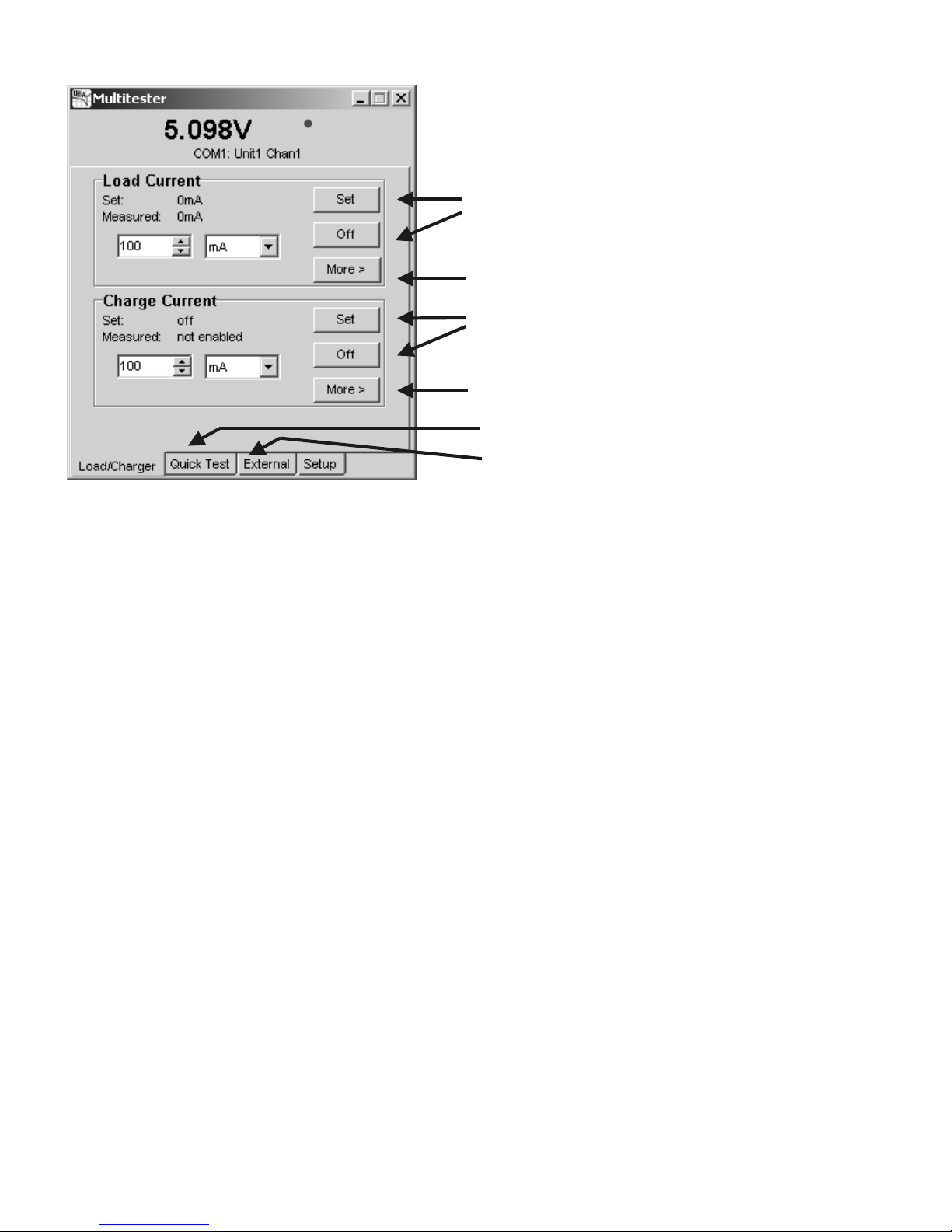
This is what the Multitester looks like:
Sets the load to the requested
current, or turns it off.
More options include:
constant resistance and power.
Sets the charger to the requested
current, or turns it off.
More options include:
Constant voltage and PWM
Quick Test page.
External load control.
Figure 10: Multitester Instrument. Use it to monitor the battery voltage while applying a
load or charge current, plus other functions.
With a battery connected, if the Multitester says 0V (zero volts) then check the connection to your battery – it should be
connected to channel one with the correct polarity.
For this test don’t use a battery pack that has any protection circuitry inside that might interfere with the testing. You
can test those batteries once you are comfortable using the UBA.
For this example, I am using a four cell 600mAh NiCd battery.
Enter a small test current (100mA for example) into the load or charge current edit boxes and click the corresponding
Set button. The battery voltage should rise a bit if you set a charge current or drop a bit if you set a load current. This
verifies that the UBA charger and load are functioning and that you have a good connection to the battery. Note, you
can’t run the load and the charger at the same time.
Besides applying a load or charge current, the Multitester can also do a constant voltage charge, a quick test
(measures battery internal resistance), or read the UBA temperature probes (if connected). Press F1 for more
information from the online help. Experiment with some of the options.
Warning: The Multitester does not check the suitability of the charge or load current that you are using. Unless you
know your battery’s condition, you should limit the charge and load current to just a few seconds so you don’t damage
it.
Close the Multitester window so that you can start a battery analyzer on that channel: it is not possible to run two
instruments on the same channel at the same time.
3.2. Setting Up the Battery Analysis
Open a battery analyzer by clicking on the battery analyzer icon on the tool bar.
The UBA Let's Get Started Guide Page 7
Page 12
Start a battery analysis.
Figure 11: UBAConsole: Starting a battery analysis. Click on the circled icon.
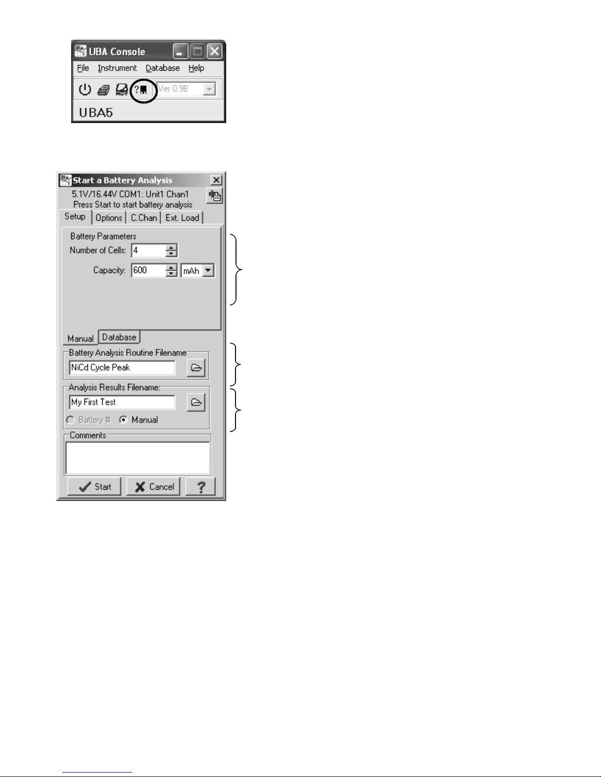
This opens up the Start a Battery Analysis dialog box:
Battery Parameters
Choose a BAR
Choose filename to store results.
Figure 12: Start a Battery Analysis dialog box: Entering analysis parameters.
There are three sections that need to be filled in before you can start the analysis.
Battery Parameters: Number of Cells and Capacity
Enter the number of cells (in series) and rated capacity of the battery. For battery packs the rated capacity and
nominal voltage should be printed on the pack. Calculate the number of cells by dividing the nominal pack voltage by
the nominal cell voltage.
Page 8 The UBA Let's Get Started Guide
Page 13

Battery Chemistry Nominal Cell Voltage (Volts per cell)
1Ah
1Ah
1Ah
NiCd or NiMH 1.2 V
SLA, lead acid or gel cells 2 V
Lithium ion or lithium polymer 3.6 V
Same battery examples:
12V Lead Acid 6 cells
4.8V NiCd or NiMH 4 cells
7.2V NiCd or NiMH 6 cells
9.6V NiCd or NiMH 8 cells
12V NiCd or NiMH 10 cells
3.7V Li-ion or Li-polymer 1 cell
7.4V Li-ion or Li-polymer 2 cells
Sometimes the battery pack manufacturer prints a nominal voltage that’s a bit higher then the standard values, in this
case round down the number of cells to a whole number.
In general, NiCd, NiMH, lead acid and gel cell battery packs have all the cells in series. Therefore, the number of cells
that you enter is the number of cells in the battery pack and the capacity is the capacity of each cell, not the sum of the
capacity of all the cells (i.e. the cell capacity is the same as the pack’s capacity). For example, the following pack,
which consists of three 1Ah cells, has a rated capacity of 1Ah and a cell count of three.
1Ah 1Ah
Figure 13: Example battery pack. Pack capacity: 1Ah, cell count: 3.
Lithium-io n packs can have cells in parallel and series. The number of cells that you enter is the number of cells in
series and the capacity is the rated capacity of the pack (sum of the capacity of parallel cells). For example, the
following pack, which consists of six 1Ah cells, has a capacity of 2Ah and a cell count of three.
1Ah 1Ah
Figure 14: Example battery pack. Pack capacity: 2Ah, cell count 3.
The UBA Let's Get Started Guide Page 9
1Ah 1Ah
Page 14

Note, you have to enter a battery capacity, even if it's not required for the BAR that you'll be using. For example, if you
are using the Datalog BAR you can enter any value for the capacity – 1mAh works fine.
Battery Analysis Routine Filename
The battery analysis routine (BAR) contains a sequence of actions that describe the battery analysis that is to be
performed. UBA Console includes BARs that you can use right away. Click on the folder icon beside the BAR
filename to display them. Select the BAR you want to use and click Open.
Select NiCd Test with Peak Charge, NiMH Test with Peak Charge, or SLA Test depending on the chemistry of the
battery that you'll be testing. Note, lithium batteries have a nasty habit of exploding or catching fire if over charged,
they should be tested in a fireproof container.
In Chapter 4 Creating a Battery Analysis Routine I’ll show you how to create your own BARs.
Hint: Double clicking on the BAR filename will open that BAR in the BAR designer.
Analysis Results Filename
In the Analysis Results Filename edit field, enter a filename to store the analysis results. I suggest that you use a
filename that contains information describing the battery you’re testing. For example, use the job number, warranty
return number or battery serial number.
Comments (optional)
Enter any comments that you would like stored in the battery analysis results file; for example, “This battery was
returned by a customer who says that it doesn't work.”. You can edit the comment text in the results file after the
analysis ends using a text editor.
3.3. Starting the Battery Analysis
Once you’ve entered in all the parameters, start the battery analysis by clicking on the Start button. If the Start button
is grayed out then some information is missing or the channel is being calibrated. The battery analysis window should
look like this:
Figure 15: A running Battery Analysis.
The battery analysis is now running. The buttons on the tool bar offer the following options in order:
• Restart the battery analysis (grayed out while battery analysis is running, click on stop first).
• Stop the battery analysis.
• Skip to the next step in the battery analysis.
Page 10 The UBA Let's Get Started Guide
Page 15

• Show the results graph.
• Hide this window (use Active Instruments on the Instruments menu to redisplay).
• Show the starting parameters.
Right click on this battery analyzer window and select Grow (or Show More Information) for more information.
Tool bar
Battery voltage. Move the mouse cursor
over the voltage to get the per cell value.
Summary of events and test results.
Current action and the elapsed time.
Additional information available on these tabs:
Measured: various measured values.
Programmed: the “set to” values.
Finished: conditions for the current action to finish.
Figure 16: Battery Analysis window (after right clicking on it and selecting Grow).
Hint: hold your mouse cursor over the Discharged value for percentage discharged, double click on it to
change the displayed value to percentage. Double click again to switch back.
3.4. Monitoring the Battery Analysis
Note that in this example the battery analysis starts in discharge. This is the default behavior of most of the BARs that
come with UBA Console. When the battery voltage reaches the cut-off value (the voltage where the battery is
considered fully discharged) the load is shut off and the charging starts (sometimes after an optional rest).
Click the View Results icon on the tool bar to get a graphical view and summary of the progress so far.
The battery analysis is finished when either the word “Finished” appears or the battery is in trickle charge (assuming
that trickle charge is the last action in the BAR).
3.5. Interpreting the Results – Is My Battery Any Good?
When the analysis is over, press the View Results icon on the tool bar to get a graph of the battery voltage and the
test results. If you've closed the battery analysis window, you can view the results from Battery Analysis Results File
Viewer from the File menu.
The UBA Let's Get Started Guide Page 11
Page 16

The analysis that I received is shown on the next page. During the discharge portion the battery voltage follows the
classic NiCd/NiMH form: an initial fast drop in voltage, a gradual decrease as the battery loses its charge, and a fast
drop at the end when the battery is fully discharged. After discharge, the charger is turned on and the battery voltage
rises quickly as it recovers, then rises gradually as the battery accepts the charge, and then peaks when it’s fully
charged. The voltage drops after the peak as the charge current is reduced from the 600mA peak charge current to
the 60mA equalization charge current.
“Battery discharged” is the tested
capacity of the battery.
Figure 17: Sample battery analysis result of a discharge followed by a charge cycle.
Now look at the text below the graph. In the One Hour Discharge: section you can see that the battery with a rated
capacity of 600mAh, was discharged 580mAh. This battery tested at 97% of rated capacity (580mAh / 600mAh x
100%). A battery with a capacity of over 90% of its rated value is considered in good condition. One with between
80% and 90% of its rated capacity is acceptable, however one below 70% to 80% should be replaced (these figures
depend on the battery and it's intended application). For the discharge capacity to be used as an acceptance criteria,
the battery must be fully charged before the test. The NiCd and NiMH BARs that come with UBA Console run for two
cycles, the first cycle leaves the battery fully charged so that the next cycle can give an accurate result. For SLA and
lithium batteries either start the test with a fully charged battery, edit the BAR so that the discharge follows a charge or
run the BAR twice.
Page 12 The UBA Let's Get Started Guide
Page 17

In the Peak Charge section notice that the battery was quick charged for 738mAh. This is greater than the measured
capacity of the battery, which is to be expected since charging is always less than 100% efficient. This also means
that the battery received the full peak charge and didn’t false peak. A false peak is a voltage peak that can occur
during the beginning of the charge cycle. It normally occurs on a new battery or a battery that hasn't been cycled in
over a couple of months. Also a poor electrical connection to the battery can cause a premature peak. Had the
charged capacity been less than the discharged capacity then, most likely, something interrupted the charging, and the
battery wasn’t fully charged. The 3h Equalization Charge is programmed for 3 hours at 60mA which equalizes the
cells and ensures that each one is 100% charged.
Note: for this example we used a simplified version of the “NiCd Test with Peak Charge.bar” BAR with just one
discharge and one charge cycle.
Conclusion:
This battery is in good condition. Cycle it regularly to keep it effective and replace it when its capacity drops to below
70 or 80%.
Hints:
• To zoom, use your mouse to select an area (top left to bottom right).
• To pan, press the right mouse button and drag.
• To change the title, click on Title (Edit menu).
Congratulations! You've completed a battery analysis. You now know how to setup and initialize the UBA, start a
battery analysis and interpret the results. The next stage is to create your own BARs so that you can get the UBA to
do exactly the analysis that you want.
4. Creating a Battery Analysis Routine
I consider the battery analysis routines the most exciting part of UBA Console. We designed the battery
analysis routine from the ground up to be so powerful and expandable that you'll be able to analyze your
batteries using methods that you never thought possible -- this has certainly been our experience. Once
you've used our battery analysis routine designer you'll never want to go back to the old "fill in the blank" type
of battery analysis.
Marc A. Venis P.Eng., M.A.Sc
President Vencon Technologies Inc.
The Battery Analysis Routine (BAR) Designer allows you to create a battery analysis using graphical techniques.
Once you learn the basics of how to design a simple BAR, you'll be able to design your own advanced BARs that can
form, recondition, and life test batteries, create and erase memory in NiCd/NiMH cells, and many other advanced
functions.
Let's create a simple BAR: a NiCd battery test based on IEC (International Electrotechnical Commission)
specific ations. From the UBA Console main window select Battery Analysis Routine Designer (File menu). You
should get an empty routine like this:
The UBA Let's Get Started Guide Page 13
Page 18

Figure 18: An empty BAR (Battery Analysis Routine).
We want our BAR to first charge the battery, so we'll add a quick charge cycle or action. Actions are the building
blocks of the BAR. There's no limit (except for screen size) to the number of actions that a BAR can contain.
Right click on the gray background and choose: NiCd/NiMH | Add Cycle | Quick Charge Cycle.
Figure 19: Adding a new action (Quick Charge Cycle) to the BAR.
Now add a standard charge cycle by right clicking and choosing NiCd/NiMH | Add Cycle | Standard Charge Cycle.
Finally add a cycle that will discharge the battery and measure its capacity. Right click again and choose
NiCd/NiMH | Add Cycle | Discharge Cycle.
Now would be a good time to save what you’ve done. Choose Save As... (File menu) and save the file as NiCd IEC
Test. You should get this:
Figure 20: The BAR with actions (action parameters not yet specified).
The BAR starts at the "Begin" circle and proceeds from left to right to the "End" circle. Each action is executed in this
left to right sequence. Click Animate (Window menu) to see this.
Page 14 The UBA Let's Get Started Guide
Page 19

Now to get this BAR to actually analyze a battery you need to set the charge and discharge values. Click on the NiCd
Quick Charge action and enter the parameters as shown below.
Enter “1” for the Charge Current
which gives a current of 1C.
This will charge the battery in
approximately one hour.
Enter “10” for the Sample Time.
The battery voltage and charge
current will be saved every 10
seconds to the results file.
Figure 21: Charge Action: Entering the charge current parameters.
Now click the Finished tab to enter the parameters that determine when the quick charge cycle ends.
Figure 22: Charge Action: Entering the finished parameters.
Enter “1.3” for the Maximum
Charge Capacity. Thus quick
charging will end when the battery
has been charged 1.3 times its
rated capacity. This is a fail safe
feature to limit over charging.
Click on the Peak Charge
checkbox. This adds a Peak
Charge page.
The UBA Let's Get Started Guide Page 15
Page 20

Enter “10” (mV/cell) for the
Peak Charge finish criteria. Thus
when the cell voltage drops 10mV
below its peak value, charging
stops.
Enter “0.05” for the
Minimum Charge so that during
the first 5% of the charging any
voltage peaks are ignored. This
skips false peaks that can occur
at the beginning.
Figure 23: Charge Action: Entering the peak charge parameters.
Click OK to save the changes.
Repeat for the NiCd Standard Charge action but use these parameters:
• Charge Current: 0.1 C (this is a slow C/10 charge that equalizes the cells without overcharging).
• Write to results every: 30 seconds (saving the results more often than this gives no additional useful
information).
• Capacity (fraction): 0.3 (at the C/10 charge rate this gives about 3 hours of charge).
Click OK to save these changes.
Now click on the NiCd Discharge action and fill in the fields as show below:
Load:
Select Relative.
Enter “0.2” for the Discharge Current.
This is the IEC standard and wil l
discharge the battery in approximately
five hours.
Enter “30” for the sample time. Since it
will take five hours to discharge the
battery it's not necessary to save the
voltage and current more often then this.
Figure 24: Discharge Action: Entering the discharge current parameters.
Click the Finished tab:
Page 16 The UBA Let's Get Started Guide
Page 21

Enter “1.0” for the Cut Off Voltage. This is
the value specified in the IEC standard.
Figure 25: Discharge Action: Entering the finished parameters.
Click OK to save these parameters and then Save (File menu) to save the BAR file.
That’s it. You’ve created a new BAR that you can use whenever you want.
4.1. “Advanced” BAR Concepts
Renaming and Deleting Actions
Right click on an action to rename or delete it.
Rearranging Actions
If you would prefer to have the order of actions changed, drag any action to a new location. Don’t forget to save
afterwards.
Figure 26:
The "One Hour Discharge" action is dragged to be after the "Equalization Charge."
Using BAR Routines
In order to keep the BAR layout uncluttered and easy to maintain, you can use subroutines, called routines, to group
actions. For example, to add a battery analysis routine (a discharge cycle followed by a charge cycle) right click on the
background and choose: "NiCd/NiMH | Add Routine | Battery Analysis Routine. Now if you click on the newly
created button you'll get the BAR subroutine. Click on Animate (Window menu) to see the action flow.
The UBA Let's Get Started Guide Page 17
Page 22

Figure 27: Action flow in a subroutine.
Relative Currents and Time
You might have noticed the use of relative currents (based on the battery's C current) and time based on capacity.
This is different from other battery analysis systems. The use of relative currents allow you to design BARs that work
independently of battery capacity. If you prefer, you can still specify absolute values.
Figure 28: Here we have a relative load current of 1C. If you ran this BAR on a 600mAh
battery you'd get a 600mA load, on a 2Ah battery you'd get a 2A load.
Page 18 The UBA Let's Get Started Guide
Page 23

4.2. BAR Actions
There are five actions that you can use to build a BAR:
Figure 29: All available actions .
NiCd/NiMH Quick Charge Cycle, Standard Charge Cycle and Trickle Charge Cycle:
These are actually all the same – just a blank constant current action than can be terminated by a number of methods.
You would normally use this for charging NiCd and NiMH cells. But you can use it for other functions. We use it to
prequalify a lithium ion battery.
NiCd Discharge and Li-ion/SLA Discharge:
These are the same discharge action. You can choose the load (constant current, power, or resistance) and the
termination method. You would specify about 1 V per cell for the cut off for NiCd or NiMH, about 2.75 V for lithium,
and about 1.75 V for SLA.
Li-ion/SLA Standard Charge
This is the constant voltage charging action designed for lithium ion, lithium polymer and SLA/gel cells/lead acid
batteries.
Routine (from NiCd/NiMH->Add Routine->Empty Routine)
This is an empty routine. Click on it to open the subroutine. There a couple of routines already populated with some
actions. They are accessible from: NiCd/NiMH->Add Routine->.
Goto
This branches either forward or backwards. You can specify the number of times to branch (i.e. run a
charge/discharge cycle 10 times) and allow a discharge action to break out of the loop before the repeat count is
reached.
4.3. BARs Included with UBA Console
Although making your own BARs isn’t very difficult (we just did one last section, remember?), there’s no glory in
reinventing the wheel; therefore we’ve included a few BARs with UBA Console that have been written by our resident
battery expert, me! I suggest that you use them, at least until you have gained enough confidence to write your own.
And remember, when using a new BAR for the first time, watch the battery analysis while it's running the first time to
ensure sure that it does what you intended it to do.
Actually the easiest way to create BARs is to modify existing ones. Modify ours, we don’t mind. There are many
parameters in a BAR and it’s easy to over look something. By modifying a working one you increase the chance of
getting it working the first time.
The UBA Let's Get Started Guide Page 19
Page 24

Hint: the BARs that came with your software are designed to minimize the chance of your overwriting them
(specifically, the Owner field is filled in), but if you do, you can get a new copy from your install CD in the
Image/BARs folder.
See Appendix C for a list of the BARs included with UBA Console.
5. Advanced Topics
5.1. Choosing and Setting Up a Power Supply
The UBA requires a 15 to 24V DC voltage at sufficient current to power both its internal chargers. The voltage needs
to be at least 3V greater than the maximum battery pack voltage during charge (for NiCds and NiMH this would be
about 1.6V per cell, for sealed lead acid: 2.5V per cell and for Li-ion: 4.2V per cell). An unregulated power supply can
be used, but the charge current measurements will be less accurate.
If you are using a power supply that can’t provide the full 2A per channel charge current with an additional 250mA for
the UBA itself then you can set the UBA to limit the current that it draws. This is done in the calibration file or entered
manually each time UBA Console is run, as explained below.
Power Supply Description Lines in Calibration File
Each UBA has its own calibration file (xxxx.uba, where xxxx is the serial number of the UBA). In t he calibration file
there’s three lines that describe the power supply that’s powering the UBA.
For example, the 19V 4.5A power supply that comes with the UBA5GP combo is described as follows:
PowerSupplyV: 19
PowerSupplyI: 4.5
PowerSupplyR: 0
If you purchased a UBA combo from us then we’ve already entered the power supply parameters into the calibration
file. If the UBA is used with a different power supply or if it wasn't purchased as a combo then you can edit the
calibration file to prevent overloading of the power supply. An overloaded power supply will either shut down, drop the
output voltage or burn out.
You can edit these lines with a text editor (notepad works fine). UBA Console only uses the maximum current value
(PowerSupplyI), the voltage and resistance lines are ignored, but the voltage value should be filled in for future
compatibility. Note, a value of 0 for the power supply current means that no current limiting is necessary (i.e. your
power supply has a current output of at least 4.25A).
Temporarily Changing the Power Supply Current Limit
You can view the current limit by clicking on the "General" tab in the UBA Window:
Page 20 The UBA Let's Get Started Guide
Page 25

Figure 30: UBA Display window (click on the UBA icon in the UBA Network window to
get this display, then click on the General button). In this example, the UBA Console S/W
will limit its power supply current draw to no more than 1.0A.
You can change this value by entering in a new one, but note that this number is not saved into the calibration file.
Remember that a value of 0 (zero) means that the UBA will not limit its power supply current draw (but will never
exceed 4.25 A).
Sharing Power Supply Current Between Both Channels
You can specify that both channels equally share the power supply current by checking the Evenly divide between
channels radio button on the Charger tab in the Options dialog box (File menu). This evenly divides the power
supply current among both channels so that each channel can have up to half the maximum current.
Figure 31: Option dialog box showing the Charger current settings.
Examples:
1. You have a power supply with a 4.25A or greater output current rating. Since the power supply can supply
both channels with their maximum current rating (2A) with at least 250mA left over for the UBA's electronics,
then no output current limiting is necessary. Either a setting of 4.25 or greater or 0 in the power supply rating
box is acceptable. The Power Supply Current radio button selection has no effect.
The UBA Let's Get Started Guide Page 21
Page 26

2. You have a 1.0A power supply which doesn't supply enough current to power both channels at their maximum
charge current. You should enter 1.0 as the power supply current in the UBA's calibration file. The setting of
the Pow er Supply Current radio selection box is important. If Evenly divide between channels is selected
then each channel will get up to almost 500mA charge current. If Share as required between channels is
selected then one channel can use almost the full 1A charge current and the other channel gets nothing.
Notes:
• If you enter in power supply rating higher then what your power supply can provide then you risk damaging
your power supply.
• If your power supply can't provide the maximum current to each channel and you have checked the Share as
required between channels radio button then you should only run one battery analysis at a time. Otherwise
one channel can have little or no current available for charging. The software isn't able to delay starting a
charging cycle on a channel until the required current is available.
• If you are running the UBA off of two power supplies, one for the UBA's electronics and one for charging (i.e.
the UBA5-30V) then enter a negative number, i.e. -3.0 if you have a 3A power supply. The negative sign
means that the power supply is not powering the UBA's electronics and no margin need be made for that.
• The UBA uses the peak current from each channel for sharing the power supply current. So if one channel is
on PWM charge (i.e. the charge current is pulsing) the peak current is used. This is very conservative and will
be looked into in the future.
• If you are using the UBA exclusively for testing primary batteries then set the maximum power supply current
to 0.001 (1mA), not 0. The UBA will then never turn on the charger
5.2. Importing Results into a Spreadsheet
You can import the results file (.uba file) into a spread sheet for further analysis or graphing.
Microsoft Excel
In Microsoft Excel, select Open... (File menu). For Files of type: choose Text Files (*.prn *.txt, *.csv), type “*.uba”
into the File name: box and press Enter or click Open. Choose a results file and cl ick Open. In the Text Import
Wizard dialog box choose Delimited, click Next and then select Comma as the delimiter. Click Finished.
A faster method is to add a “.csv” file extension after the “.uba” on the results file (i.e. My Test.uba.csv). Double click
on the file and Excel will start up and import the results file.
In the private section on our web site you’ll find a macro for Excel that imports and graphs results files automatically.
OpenOffice.org Calc
In OpenOffice.org Calc, select Open... (File menu). For Files of type choose Text CSV (*.csv, *.txt), type “*.uba into
the File name box and click Open. Now locate the file you want to import. The Text Import window will pop open.
Choose Comma for the Separator options and click OK. The UBA results file will be imported into Calc ready for
graphing.
5.3. Warnings
The negative battery inputs on both channels are connected to the ground on the PC and to the ground/earth on the
UBA power supply. Only test batteries that are floating (i.e. not connected to anything). We sell a self powered RS232
opto-isolator designed specifically for the UBA that will isolate the UBA from the PC’s ground for testing batteries that
aren’t floating (contact us for assistance).
Page 22 The UBA Let's Get Started Guide
Page 27

5.4. Current and Power Limitations
Load Limit: 3A and 45W
The UBA can discharge at up to 3A per channel, with a maximum dissipation of 45W. During discharge, the UBA
converts the battery current into heat which it dissipates with its chassis. The power is limited to 45W per channel to
prevent over heating the chassis and load transistors. The UBA's internal fan turns on at a power dissipation of 10W
on either channel.
Thus for batteries 15V and lower you'll be able to use the full discharge current of 3A. For batteries higher then 15V the
UBA will reduced the current to keep within it's 45W maximum.
If you want a higher load current, then combine both channels (see the section UBA Accessories - Channel
Combiner) or use a series power resistor (contact us for more details). Don't worry about damaging the UBA from
over-current or over-power as UBA Console automatically limits the current to safe values.
Charger Limits: 2A (and 28W internal dissipation)
The UBA can charge at up to 2A per channel (power supply permitting). It uses a low noise linear constant current
charger that drops the voltage from the power supply to your battery. The difference between the power supply
voltage and the battery voltage is absorbed by the UBA's charger. The power is limited to 28W per channel to prevent
overheating the UBA.
Thus, when charging a single cell, the UBA might limit the charge current. For example if you have a UBA5GP with a
19V power supply and you want to charge a single 1.2V cell at 2A, the UBA would have to dissipate about 35W ((19 –
1.5V) x 2A). This is worst case, it's actually less than this as any wiring would drop the power supply voltage. So in
this case the UBA would reduce the charge current to about 1.7A. If you want to charge single cells or low voltage
battery packs at high currents then either combine two or more channels, use a lower voltage power supply (but not
less than 15V), charge the cell in series with other cells or add a resistor in series with the cell (contact us for more
details).
The UBA Let's Get Started Guide Page 23
Page 28

Appendix A – Troubleshooting
Win95 and NT: Software Installation Problems
UBA Console requires files that don’t come with a fresh install of Windows 95 or NT4. If you have a Microsoft Internet
Explorer or Microsoft Office installed, you shouldn’t have a problem. Otherwise you can get the missing files off of our
website (www.vencon.com/downloads/Win95-NT.html
website.
Icons on UBA Console Aren’t Displayed (for Win95/98 and NT only)
If the icons on the tool bar don't display correctly you need to upgrade your comctrl32.dll file (Microsoft Windows
Common Controls). The file 50comupd.exe installs the Internet Explorer version 5.0 version of this DLL. See above
for location of files.
A required .DLL file, HHCTRL.OCX, was not found (for Win95 and NT only)
If you get this error then you don’t have the Microsoft’s HTML Help software installed. Install it by running the
hhupd.exe file. See above for location of files.
The DLL with the name "SHLWAPI.DLL" is not found (for Win95 and NT only)
If you receive this error message, you will need to install shlwapi_Win95.exe or shlwapi_NT4.exe. See above for
location of files.
) , the UBA Console install CD (in the “Win95_NT”), or Microsoft’s
Self Test
The UBA does a self test every time it’s turned on. If the self test passes, it will flash the channel LEDs and the fan.
You can also test the serial communications by connecting the serial cable that came with the UBA between the two
serial connectors on the back of the UBA. Power on the UBA. If the UBA’s serial communication is functioning, the
UBA will continually do a self test and you’ll see the front channel LEDs flash.
Communication Monitor
Before the UBA is initialized, the channel one red LED will show very fast flashes when it detects any activity on the
serial port. So if you are having problems connecting to the UBA and the channel one LED isn't flashing during
initialization, then the UBA isn't receiving any commands.
Page 24 The UBA Let's Get Started Guide
Page 29

Appendix B – FAQs
Software
Can I run a life cycle test on my battery?
Yes. Change the repeat count in a BAR that cycles the battery to a large value (99,999 for example). Have the
charge or discharge actions only write to the results file every minute or so in order to reduce the size of the results file.
When the life time test is over (either by the number of cycles or the battery capacity), view the results file in the
Battery Analysis Results Viewer (File menu) and select Write Report (Results Viewer File menu). This will write a
comma separated table of capacity vs cycle number which can be loaded into your favorite spreadsheet. Note, a long
life test can take a few minutes to display. It’s best that you not view it while a battery test is running since you can
lose communications. Use a second computer, or start up a second instance of UBA Console for viewing the results
file.
How complicated can I make a Battery Analysis Routine (BAR)?
You can make a BAR as complicated as you want. We’ve even had customers make them with nested loops where
the inner loop simulated the load on their device (for example 5 seconds low load and 1 second high load for a twoway radio) and the main loop did a life cycle test. The only limit is screen size, and you can get around that by using
routines.
Battery Testing
How do I know how many cells are in my battery pack?
In order to get the number of cells in a battery pack, divide the battery pack’s nominal voltage (usually printed on the
pack) by 3.6V for li-ion cells, 1.2V for NiCd/NiMH cells or by 2V for SLA cells.
My battery pack has four 1000mAh cells in series. What’s the pack’s capacity?
In this case, the packs capacity is 1000mAh. It would be 4000mAh had the cells been in parallel.
What’s the quickest I can test a battery?
Well you can do a Quick Test in just a few seconds which measures your battery’s internal resistance. This tells you
how bad the battery is, but not how good it is. A high internal resistance means a battery is in poor shape, a low
internal resistance gives little indication about its capacity.
If you have the time, a full battery discharge is best. This can be done in as little as 1 hour (or 30 minutes if you don’t
mind stressing your battery a bit), provided the battery is initially fully charged and the load current is within the UBAs
capabilities. Unless the battery is designed for high rates of charge and discharge, discharging or charging it in less
than one hour is not advisable as it unnecessarily stresses the battery and gives low capacity results. A full chargedischarge cycle can take as little as three hours on a NiCd, NiMH, li-ion or li-polymer battery and as long as a day on a
SLA or gel cell battery. If you have a specific test requirement feel free to contact our technical support department for
assistance.
Can I test primary (non rechargeable) batteries with my UBA?
Sure. But you can only discharge them and the test is destructive (i.e. you can’t use the battery again, except, of
course, as a paperweight).
The UBA Let's Get Started Guide Page 25
Page 30

I have a lot of batteries (or cells) to test. Can I test them by putting them in series?
Yes and no. If the batteries are voltage charged, like lead acid or lithium ion, then the answer is no you can’t charge
them since any imbalance will result in some cells being overcharged and some undercharged. For NiCd or NiMH
batteries, you can charge them in series provided they are the same model and initial state of charge. For discharging
you’ll get the capacity of the weakest cell.
General
How to you pronounce UBA?
Spell it out, “U” “B” “A”. Do not call it an “Ooba”!
How many UBAs can be connected together?
Theoretically 253, although nobody has every tried that many (at least as far as we know). The record is 30 UBAs on
one serial port (that’s 60 channels). Don’t try this with Win95, Win98 or WinMe as they have limited graphical
resources.
How often does the UBA need to be calibrated?
We recommend a one year calibration interval. We have found that it’s rare for a UBA being recalibrated to require
any changes to the calibration file since there are no adjustable parts inside that can drift.
Can I use a UBA to turn on my charger? Can I use my charger to start a discharge cycle?
Yes and yes. The accessory port on the UBA, which is located inside, has two digital outputs and two analog inputs.
You can control the output lines with your BAR (use external battery load setting) and respond to the analog input
signals (simulate temperature). We sell a connector to bring the accessory port to the back of the UBA and also an
optical isolated output connector. More information can be found in our External Devices Manual located in the
Support : Reference Manuals section of our website.
My UBA gets hot during operation. Why isn’t the fan turning on?
The fan only turns on when the UBA gets very hot. You can have the fan turn on earlier by reducing the turn-on power
limit on the General tab in the Options dialog box (File menu). Enter a power less than 10 Watts (6 for example) and
the fan will turn on when that power (or more) is being dissipated.
My battery is very small and the minimum charge and load current are too high for it.
For small batteries, less than 100mAh, you might consider having the UBA customized by us for low currents. We
have expertise in customizing the UBA all the way down to 1uA full scale.
I have a question about the database.
Stay away from the database functions in UBA Console (unless you really need them). They are only partially
implemented and are not written very well. We will be rewriting them in the future and can’t guarantee backwards
compatibility.
So where is the power switch?
There is none. The UBA draws so little current when it’s not in use that there was no point in installing a power switch.
We’ve thought about having UBA Console turning off the green power LED when you close the UBA network, but that
would be confusing.
Page 26 The UBA Let's Get Started Guide
Page 31

Appendix C – Included Battery Analysis Routines
The following BARs are included with the UBA. You’re free to examine and modify them in the Battery Analysis
Routine Designer and save them under a different nam e.
Battery Analysis
Routine
NiCd Peak Charge NiCd
NiMH Peak Charge NiMH
NiCd Test with Peak
Charge
NiMH Test with Peak
Charge
NiCd Test with Timed
Charge
NiMH Test with Timed
Charge
NiCd Forming NiCd
NiMH Forming NiMH
NiCd Recondition NiCd
NiMH Recondition NiMH
Chemistry Used for:
NiCd
NiMH
NiCd
NiMH
Peak charging a NiCd or NiMH battery in any initial
charge state. If the battery hasn’t been cycled in a
while, the peak charge might end prematurely due to
false peaks. If this happens then you should use the
NiCd Test with Timed Charge or NiMH Test with
Timed Charge routine.
Cycling a battery to determine its capacity and
exercising it. Use this routine if the battery is regularly
cycled. If you’re getting premature false peaks while
charging then you should use the NiCd Test with
Timed Charge or NiMH Test with Timed Charge
routine.
Cycling a battery to determine its capacity and
exercising it. This routine takes longer then the NiCd
Cycle with Peak Charge / NiMH Cycle with Peak
Charge routine but it won’t false peak on a battery that
hasn’t been cycled in a while.
Forming new batteries or those that haven’t been
charged for a few months. It slow charges the battery
for 16 hours followed by a discharge and then peak
charge.
Reconditioning NiCd and NiMH batteries with low
capacity. It uses a two step discharge: the battery is
discharged then deep discharged followed by a peak
charge. This cycle is repeated twice. Restoration of
capacity works best on cells that don’t suffer from
physical deterioration (normally the separator).
The UBA Let's Get Started Guide Page 27
Page 32

Battery Analysis
Routine
Chemistry Used for:
Lithium-ion
Li-ion Charge
Lithium-polymer
Lithium-ion
Li-ion Test
Lithium-polymer
SLA Charge
SLA Test
SLA, gel cell or
lead acid
SLA, gel cell or
lead acid
Datalog N/A
Cyclone Test
Cyclone SealedLead cells
Charging a lithium ion or lithium polymer battery.
Before using this routine, check that the default charge
voltage (4.2V) is appropriate for the battery otherwise
the battery can be damaged or explode.
Cycling a lithium ion or lithium polymer battery to
determine its capacity. Before using this routine, check
that the default charge voltage (4.2V) is appropriate for
the battery otherwise the battery can be damaged or
explode.
Charging a sealed lead acid (SLA) or wet lead acid
battery. It uses a two step charge algorithm consisting
of a current limited charge to 2.40V/cell followed by a
float charge at 2.3V/cell.
Cycling your battery to determine its capacity and
exercising it. It discharges the battery and then
charges it back up using a two step charge algorithm.
Logging the voltage on the battery or accessory input s
and logging temperature.
Cycling a Cyclone Sealed-Lead cell. This routine
discharges the cell and then charges it back up.
Page 28 The UBA Let's Get Started Guide
Page 33

UBA Accessories – Optional Temperature Probes
White Temperature Probe
If the UBA came with temperature probes then you'll be able to view and record the battery temperature during a
battery analysis. Afterwards you can load the results into a spreadsheet and plot the temperature curve along with
battery voltage and current.
That's not all. You can program the software to stop battery charging when the battery reaches a certain temperature
or rate of temperature rise (dT/dt).
Connecting The Temperature Probes to the UBA
The temperature probe set comes with two temperature probes, a blue and a white one, and a connector on the back
of the UBA. Except for the colour, they are identical. The two temperature probes plug into the back of the UBA, one
of them into the upper two pins, the other one into the lower two pins. The centre two pins are not used. In the
calibration file the probes are named “BlueTherm” and “WhiteTherm”. If you plug the blue probe into the upper part of
the connector and the white probe into the lower part of the connector then they will match the description in the
calibration file. If you wish, you can change the probe names in the calibration file.
Blue Temperature Probe
TEMPERATURE
PROBE
Temperat ure Probe Connector
(on back of UBA)
Figure 32: Temperature Probe connections on back of UBA chassis.
Checking the Operation of the Temperature Probes
Start UBA Console and initialize the UBA network. Start a Multitester and choose the Setup tab. Click on the Get
Battery temperature from: drop down list and choose a temperature probe (if a probe is in use, or an other accessory
is using the same accessory analog input, it won't appear as a selection). If there are no probes listed then your
calibration file isn't set up for temperature probes. Shortly after selecting a temperature probe, the probe's temperature
should appear.
Connecting the Temperature Probes to the Battery
We sell two types of temperature probes. The non-magnetic ones can be taped to the battery, ideally near the centre.
The magnetic ones will stick to the battery. If the battery is non-metallic then you can tape the magnetic probe on.
You want the probe to contact the warmest part of the pack.
The UBA Let's Get Started Guide Page 29
Page 34

Connecting to an existing Thermistor Inside the Battery
If the battery pack has a built in 10k thermistor with both leads floating or one connected to battery negative then you
can use it as the temperature sensor (you'll need a temperature probe connector on the back of the UBA for this).
Contact us for more information.
Running a Battery Analysis
When you are setting up a battery analysis, click on the Options tab and select a temperature probe. If you want the
charging to be controlled by temperature then you'll need to set this in the BAR. For NiCd/NiMH charging, open the
BAR in the BAR designer and click the charging action. Select the Finished tab and check Temperature Probe. On
the Temperature tab you can set the temperature rise rate and maximum temperature. When enabled, if either of
these conditions are met then the charging cycle ends.
Figure 33: Temperature conditions that terminate battery charging for NiCd/NiMH cells.
The BAR Designer has a option where if the temperature probe reaches a specified temperature, the battery analysis
is ended.
Figure 34: Maximum battery temperature in a BAR (mainly used for lithium cell charging).
Page 30 The UBA Let's Get Started Guide
Page 35

When Is a Battery Fully Charged?
The most important part in fast charging is when to stop. Overcharging a battery can damage it and is dangerous. In
the graph on the next page we deliberately overcharged a NiMH battery to show you what happens. Look at the
battery temperature line. It rises slowly at first then quickly rises when the battery is almost 100% charged. The fast
charging stops when the temperature reaches the maximum temperature of 45ºC as set in the BAR. If the fast
charging didn't stop then the temperature would continue to rise and the battery would eventually vent (release
electrolyte) causing permanent battery degradation. Overcharging a lithium-ion or lithium-polymer battery can result in
the battery bursting into flames.
Now look at the voltage graph. This is the most common method to terminate a NiCd/NiMH quick charge as it requires
no temperature sensing. The "X" axis is the fraction of charge being put into the battery. At "1.0", in theory, the battery
would be fully charged. In actuality the battery isn't fully charged until a bit past this value. The line at "A" is the point
where the battery voltage has dropped enough (about 2mV/cell) so that a peak charge would have stopped there.
Notice at "A" the battery receives about a 5% overcharge (based on a theoretical 100% efficiency charge) which is
acceptable.
Now look again at the temperature graph. We've drawn two temperature curves - one for the battery temperature and
the other for the rate of battery temperature change. The temperature peaks at line "B" which is when the charger was
turned off. A temperature cut-off works best as a backup method of ending the battery charge cycle. Temperature
rate of change (dT/dt) is a better method of determining when the battery is fully charged. In this example, if you would
have specified a maximum temperature rise of 1ºC/minute then the charging would have terminated exactly at the
100% efficiency fully charged mark. Since rate of temperature change is dependent on the battery pack construction
(the less cooling the faster the temperature will rise) it's difficult to come up an optimum value to use.
What's best? We recommend that you start with a maximum battery temperature of 35 to 40ºC and a maximum dT/dt
of 0.5ºC/minute to 1.0ºC/minute. If the charging is stopping too early then increase these values. You can tell what
caused the charging to stop from the text at the bottom of the results viewer.
You can use the UBA to create your own chart. Run a battery test with a temperature probe. Then import the results
file into a spreadsheet program and use a simple formula to get the dT/dt (in degrees Celsius per minute): ((Temp2Temp1)/(Time2-Time1) * 60). For this graph we matched up the end of fast charge and beginning of slow charge
which compensates for the voltage drop of the cable (during peak charge the battery voltage is sampled with the
charge current on, afterwards the battery voltage is sampled with the charge current off).
The UBA Let's Get Started Guide Page 31
Page 36

Over Charging a NiMH Battery Pack
A B
Voltage per Cell
1.60
1.55
1.50
1.45
1.40
1.35
1.30
1.25
50
40
Bat t ery Temp erature
30
20
Bat t ery V ol tage
10
dT/dt
0
-10
-20
0.00.51.01.5
dT/dt (ºC/Min) Temp (ºC)
Charging Capacity (1.0 = 100%)
Figure 35: Test results from deliberately over charging a battery pack.
Page 32 The UBA Let's Get Started Guide
Page 37

UBA Accessories - Channel Combiner
UBA
Channel Combiner
Single UBA
The channel combiner allows you to combine both channels of the UBA doubling the charge and discharge current
and power. To do this, connect the battery positive terminal to both positive battery inputs and the battery negative
terminal to the negative battery input (the negative battery inputs are already wired together).
The Channel Combiner makes this easy to do. Plug one end of the channel combiner into either positive input (red) on
the front of the UBA and the other end into the other positive input. The battery to be tested is then connected to one
of the negative (black) inputs (it does not matter which one) and to the banana input on the channel combiner. See
diagram below.
-
Battery
being
tested
Figure 36: Using the UBA Channel Combiner.
+
Two or More UBAs
Combine the channels of two or more UBAs the same as you combine the channels on one UBA, but in addition to
connecting the positive inputs in parallel you have to connect the negative inputs between the UBAs. If you don't do
this then battery current will flow through the serial cable and the power supply lines.
Software Instructions
Once you've physically connected the channels in parallel you have to set up a “virtual UBA” that controls these
combined channels. The virtual UBA acts as if it's a single channel, but with higher current and power limits plus some
additional features.
1. Start a virtual UBA by clicking on the Virtual UBA icon:
The UBA Let's Get Started Guide Page 33
Page 38

2. Add channels to it by clicking on the Channel menu:
3. Then start a battery test on the virtual UBA by clicking on the Instrument menu:
Figure 37: Software instructions for combining
channels and starting a battery analysis.
Page 34 The UBA Let's Get Started Guide
Page 39

UBA5 Specifications
Battery Types
Chemistry: NiCd, NiMH, lead acid, gel cell, Li-ion, Li-poly and all primary cells.
Two ranges: 0 to 6.5V & 0 to 24V, accuracy 0.2% rdg ±10mV.
Voltage &
Number of cells (in series):
Capacity: 20mAh to 120Ah (or more)
Internal Load (two per UBA)
Type: Programmable constant current.
Current: 12mA to 3000mA in 12mA increments with 45W limit.
Load cycle terminated by
any of the following conditions:
Accuracy: 0.5% reading ±2mA.
Resolution: 0.1mAh.
Internal Charger (two per UBA)
Type: Programmable constant current, voltage and duty cycle.
Current: 20mA to 2.0A in ~20mA increments with internal 28W limit.
Charge cycle terminated by any of the
following conditions:
o NiCd, NiMH: 1 to 16 cells.
o Lead acid, gel cell: 1 to 9 cells .
o Li-ion, Li-poly cells: 1 to 5 cells.
Cut off voltage.
Maximum time and/or capacity.
Temperature (with optional probes).
Peak (delta V).
Maximum time and/or charged capacity.
Temperature (limit or dT/dt - with optional probes).
Miscellaneous
Battery input: Banana connectors (two pairs of cables included).
Accessory ports: Two (extra analog and digital lines for accessories).
Power: DC: 15V to 26V, 4.5A max.
120/230VAC universal power supply comes with UBA “combos”.
Approvals: CE and FCC
Size, Weight: 130mm x 170mm x 75mm (WxLxH), 820g
Warranty: Two year parts and labour.
Software: UBA Console included (for Win9X/NT4/ 20 00/ XP/V is t a/ Linux-Wine)
Two Year Limited Warranty
Warrants that the UBA and accessories are free from defects in materials and workmanship for a period of two
years from the date of purchase. Within this period contact Vencon to obtain a RMA number then send any
malfunctioning units to an authorized repair centre prepaid. We will repair or replace it at our option without charge for
parts and labour and return it in a timely manner at our expense. Any product which has been subject to misuse or
accidental damage is excluded from this warranty.
The foregoing limited warranty is Vencon’s sole warranty and is applicable only to products sold as new. The
remedies provided herein are in lieu of a) any and all other remedies and warranties, whether expressed, implied or
statutory, including but not limited to, any implied warranty of merchantability or fitness for a particular purpose, and b)
any and all obligations and liabilities of Vencon for damages including, but not limited to accidental, consequential, or
special damages, or any financial loss, lost profits or expenses, or lost data arising out of or in connection with the
purchase, use or performance of the Product.
The UBA Let's Get Started Guide Page 35
 Loading...