

VENCO VAX-J series, VAX-JR series, VAX-J 400-50, VAX-JR 400-50, VAX Installation, Operation And Maintenance Manual
...
INSTALLATION – OPERATION MAINTENANCE MANUAL
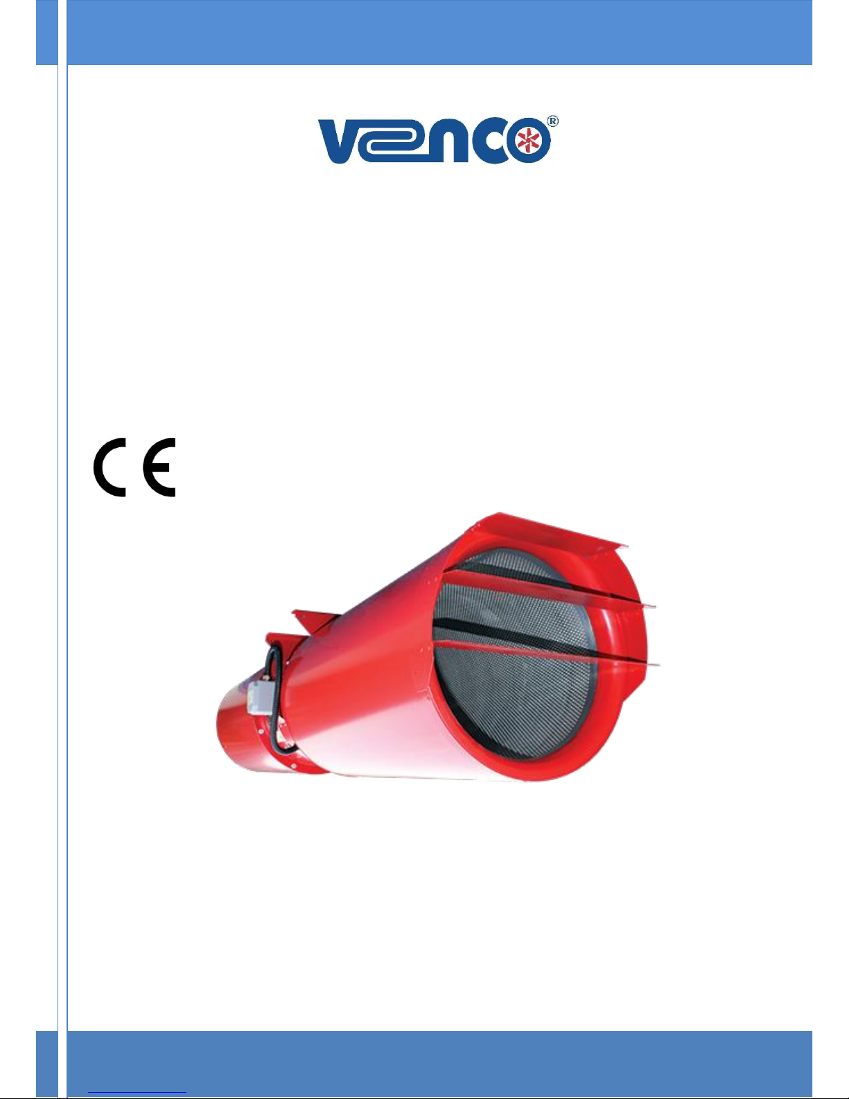
AXIAL JETFANS
VENCO Havalandırma ve Makina San.ve Tic. A.Ş.
2004. Cad. No:5 45400 OSB Turgutlu – MANİSA / TÜRKİYE
Tel: 0090 (236) 332 5070 Fax: 0090 (236) 332 5030
www.venco.com.tr venco@venco.com.tr
2017.03
2017.03 1 / 6
INDEX
1. INTRODUCTION ..................................................................................................................................... 1
2. GENERAL IDENTIFICATION OF DEVICE TYPE and MODEL ............................................................... 2
3. TECHNICAL DATA ................................................................................................................................. 2
4. TECHNICAL SPECIFICATIONS ............................................................................................................. 3
5. INSTALLATION ....................................................................................................................................... 3
6. OPERATION ........................................................................................................................................... 4
7. HANDLING & STORAGE ................................................................ ........................................................ 5
8. MAINTENANCE ...................................................................................................................................... 5
9. FAULT DETECTION ................................................................................................ ............................... 5
10. WARRANTY ........................................................................................................................................ 5
11. ANNEX ................................................................................................................................................ 6
11.1. Annex-1: Electrical Wiring Diagrams ................................................................................................ 6
1. INTRODUCTION
Before operating VENCO branded VAX-J and VAX-JR Axial Type Jetfans, please examine carefully the
instruction manual and keep it. Do not use devices as a workbench or a storage area. VENCO VAX-J and
VAX-JR Axial Type Jetfans can only be operated in conditions of intended design and technical
specifications.
BEFORE OPERATING READ THIS MANUAL and KEEP IT IN REACH OF A SERVICE
PERSONNEL.
THIS FAN CAN ONLY BE OPERATED IN CONDITIONS OF INTENDED DESIGN AND
TECHNICAL SPECIFICATIONS. OTHERWISE THE RESPONSIBILITY BELONGS TO
INSTALLER.
DO NOT USE THIS FAN IN EXPLOSIVE and CORROSIVE ENVIRONMENT.
RESPONSIBILITY OF THE DEFECTS WHICH CAN BE OCCURED AS A RESULT OF
UNAUTHORIZED PERSONNEL INTERVENTION TO FAN or TO BE USED NON-
ORIGINAL SPARE PARTS BELONGS TO THE INSTALLER.
2017.03 2 / 6
2. GENERAL IDENTIFICATION OF DEVICE TYPE and MODEL
Jetfan system is used for smoke exhaust when there is a fire at car parks besides the daily ventilation. It
prevents smoke to diffuse whole area and provides fire escapes as smoke free and allows people to escape.
The Axial jetfans may not be used in areas in which an explosion-capable atmosphere can be found. The
motor is found combined with the impeller in canals where the air circulation actualized. There are unidirectional and reversible models which allow design flexibility The fan cannot be installed outside without
water precaution.
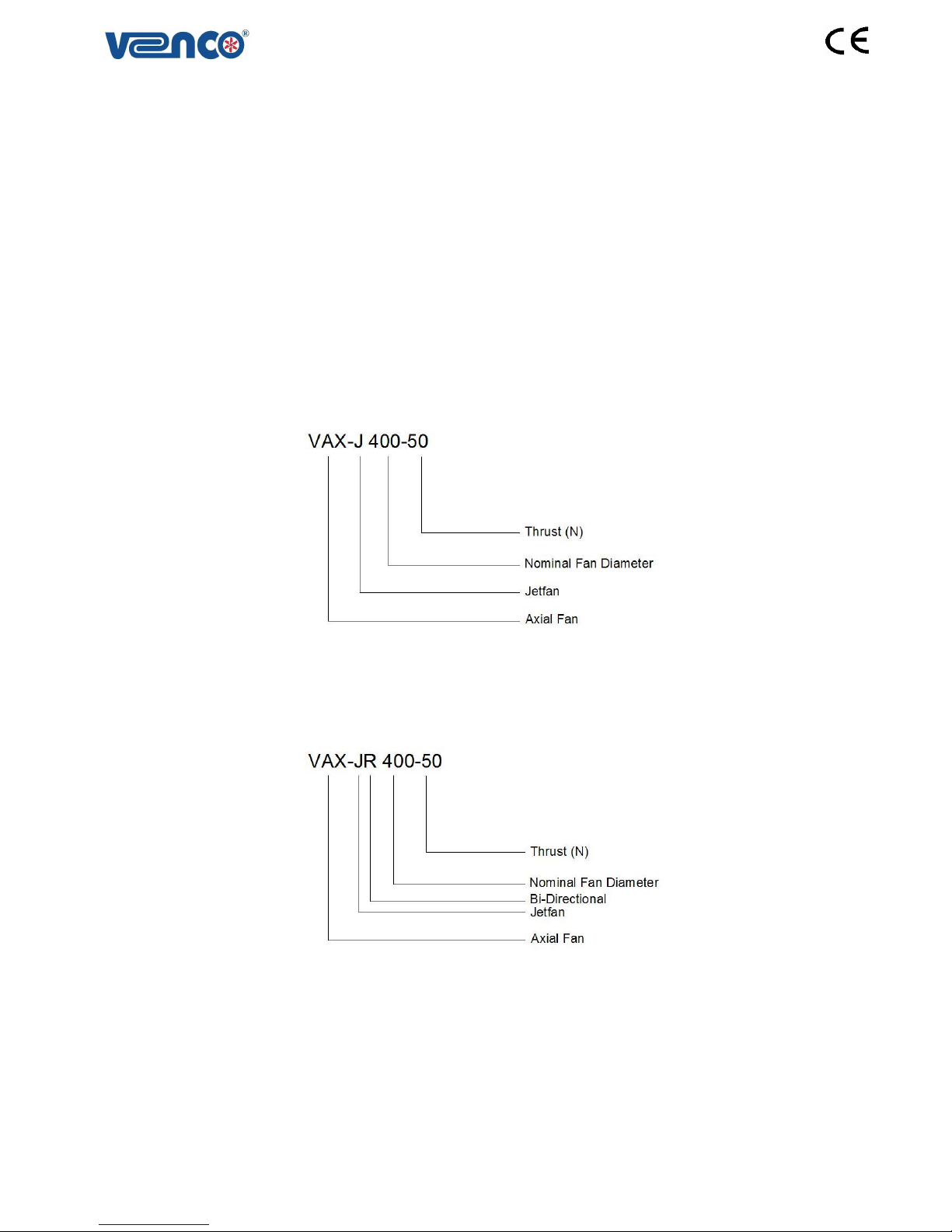
3. TECHNICAL DATA
The type key can be seen on the name plate. For Axial jetfans, it contains the following data

2017.03 3 / 6
4. TECHNICAL SPECIFICATIONS
VENCO VAX-J and VAX-JR Type Axial Jetfans;
There are bi-directional and reversible models which allow design flexibility
Ø 400 diameter
Hot deep galvanized sheet metal casing
Just aluminum adjustable blade angle
Aerodynamic profile impellers allow high efficiency and low noise
Die cast aluminum alloy fan hubs
Optimum capacity obtained hub and adjustable blade combinations
IP 67 terminal box is on the fan casing
Electrical motors with IP55
230 V, 1 phase, 50 Hz and 400 V, 3 phase, 50 Hz
Jetfan has silencers at both sides to have a laminar flow besides reducing the noise level
.Uni-directional jetfan has deflector one side and zinc plated guard. Reversible jetfan has deflector at
both ends
.The jetfans are tested and approved at 300°C temperature for 2 hours regarding to EN 12101-3
standard.
5. INSTALLATION
The fan must be installed according to the air direction label on the fan. Before the start of assembly,
examine manually whether the fan wheel runs freely. Before installation, check the minimum air gap between
the blade tip and the housing according to the following table. During assembly, secure the assembly area.
Take precautions for any access by unauthorized persons. The fan should be installed in a way that makes
service and maintenance easy. A wiring diagram is applied on the inside of the junction box or separately
enclosed. Electrical installations must be made by trained and authorized electrician.
Figure 5.1

2017.03 4 / 6
MFT, JSL, VJD, JTK parts that are used with the jet fans are illustrated on the drawing 5.1.
The connection of MFT mounting bracket, JSL silencer, VJD air router and wire mesh into the jet fan
must be done as it is shown on the drawing.
MFT and JSL parts must be connected with nuts and VJD and JTK parts must be connected with selftapping screw.
Fan Diameter
VAX-J
VAX-JR
Min. (mm)
Max. (mm)
Min. (mm)
Max. (mm)
400
5,5
6,88
5,5
6,88
6. OPERATION
Before starting, check the followings; Be sure that foreign objects are removed from fan area and
connected duct system, check connection to the electrical installation, minimum air gap between the tip of the
blade and the housing and no noise appears when starting the fan. If the air gap is correct, switch the device
on and off briefly, in order to check the direction of rotation of the fan. The rotation direction of the fan must
match up with the direction of the arrow on the housing of the fan. If the direction of rotation is wrong,
interchange two phases in order to set the correct direction of rotation.
ALL ELECTRICAL CONNECTIONS SHALL BE DONE ACCORDING TO EN 60204-1
BY TRAINNED AND AUTHORIZED PERSONNEL.
SWITCH THE ENERGY SUPPLY OFF BEFORE YOU BRING ABOUT THE
ELECTRICAL CONNECTION OF THE FAN. MAKE SURE THAT THE ENERGY
SUPPLY CANNOT BE SWITCHED ON AGAIN PREMATURELY. THE ELECTRICAL
CONNECTION MAY ONLY BE CARRIED OUT BY TRAINED PERSONNEL.
THE ELECTRICAL CONNECTION IS TO BE DONE ACCORDING TO VALID
DIRECTIVES AND ONLY BY A QUALIFIED FITTER WITH MATCHING SAFETY
DEVICES FOR THE PROTECTION OF THE MOTOR.
ALL COMPONENTS SHOULD BE EARTHED. DEVICE EARTH CONNECTION MUST
BE DONE ON TOP OF THE CONNECTOR IN JUNCTION BOX and FROM
GROUNDING SCREW WITHIN BODY.

2017.03 5 / 6
7. HANDLING & STORAGE
The fans are delivered on wooden pallets wrapped in plastic stretch. Transport the fan to the place of
assembly in its original packaging. During transport, connection cables, terminal box and wire connections
mustn’t be damaged. Load and unload the fan carefully, in order to avoid possible damage. Use suitable
lifting equipment. The fan should be stored in a safe, clean, dry, vibration free, location. A regular monthly
rapid spin of the impeller is recommended to prevent grease hardening and possible brinelling of the
bearings; the impeller should not be in the same angular position after rotation.
When dismantling the crate to gain access to the fan assembly care should be taken to avoid injury from
sharp edges, nails, staples, splinters, etc.
8. MAINTENANCE
Periodically check the screw connections, coil resistance, function of the safety components and control
elements. Only clean the fan manually, with a vacuum cleaner or with compressed air. Before service,
maintenance or repairing, disconnect the electrical connections and the impeller is stopped. The fan must be
cleaned when needed, at least once per year to maintain the capacity. The fan bearings are maintenancefree and should be renewed only when necessary. Cleaning should be done without dislodging or damaging
the impeller. Make sure that there is no unexpected noise from the fan.
In addition to routine maintenance motor bearings will in the longer term require attention. If the motor
bearings are greased through extended lubricators, a quality of grease should be periodically applied in
accordance with the information on the fan or motor nameplate and/or instructions provided.
9. FAULT DETECTION
It is necessary to turn off the fan before checking the fan and the system. During maintenance, device
electrical connections should be cut entirely. All switches and circuit breakers should be locked by brought to
the OFF position. Also “DO NOT START” sign should be placed on the control panel that will consistently
stand.
Check that the electrical connections to the unit are secure. Check that the voltage applied at the fan
terminals is as specified on the motor nameplate, and is balanced. Measure the current on each phase (one
phase in the case of single-phase motors) of the motor in turn and check that the current consumption is
within the full load current specified on the motor nameplate.
Rotate the motor shaft by hand. Investigate any sound of grinding noises, internal chaffing, rubbing or
stiffness. Any observed defect may indicate that the bearings require lubrication or replacement. Ensure that
all fixings are secure. Make sure that the fan blade is not blocked by an object, if fan is still not working,
contact your supplier.
10. WARRANTY
The warranty period starts from the date of delivery and it is for 2 years. Including all parts of the
entire fan under warranty. The maximum repairing period is 30 business days. This period starts from
the date of notification to us. Fan's warranty does not include electrical connection errors, failures that
may arise due to voltage and user errors. The warranty is only valid under condition that the fan is
assembled, operated and periodic maintenance to be made according to this manual.
ALWAYS WEAR APPROPRIATE PROTECTIVE CLOTHING (INCLUDING HARD
HATS, EYE PROTECTORS AND EAR DEFENDERS) WHEN WORKİNG IN THE
VICINITY OF THE FAN ASSEMBLY

2017.03 6 / 6
11. ANNEX
11.1. Annex-1: Electrical Wiring Diagrams
 Loading...