

Vemm Tec PTZ-BOX 3.0 User Manual
GAS-VOLUME CONVERSION DEVICE
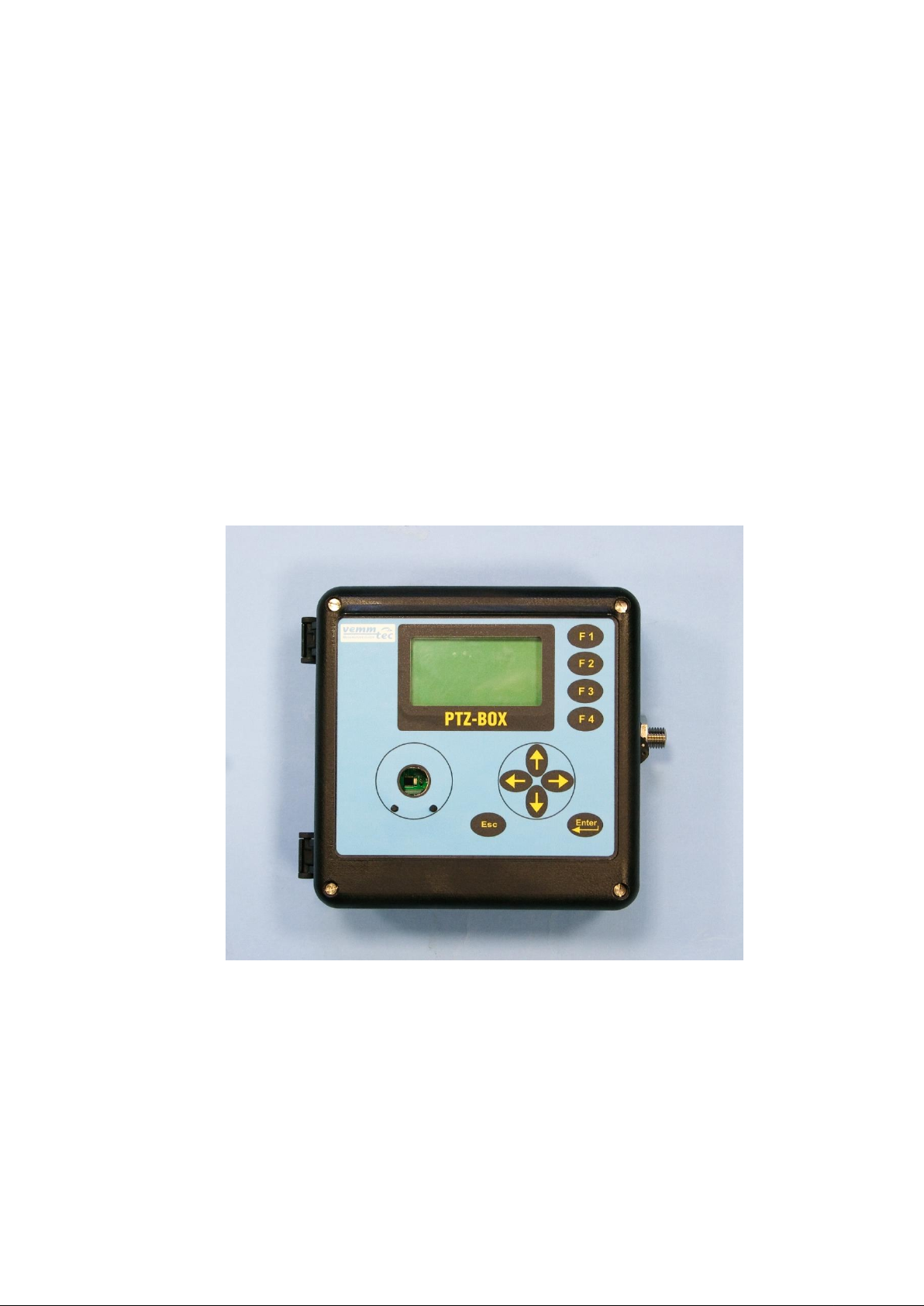
PTZ-BOX 3.0
Manual
Specifications
Technical Description
Mounting instructions
Configuration
Single-channel gas conversion device
Approved for installation in potentially explosive atmospheres.
IOM_Manual_EN_PTZ-BOX 3-0_097-102-003_2017 02.docx
February 2017

Safety Measures
This measurement device can be operated only by an operator trained in
compliance with the technical terms, safety regulations, and standards. It is
necessary to consider any other legal and safety regulations stipulated for special
applications. Similar measures also apply for special applications. Similar measures
also apply for using the accessories. The operator training must be in compliance
with Decree no. 50.1978 Coll.
The information in this manual does not have the power of a legal obligation from the
manufacturer’s side. The manufacturer reserves the right to implement changes. Any
changes in the manual or in the product itself can be performed at any time without any
previous alert, with the goal of improving the device or fixing any typographical or technical
mistakes.
IOM_Manual_EN_PTZ-BOX 3-0_097-102-003_2017 02.docx

TABLE OF CONTENTS
1 Introduction ............................................................................................. 3
1.1 Basic device description ....................................................................................... 3
1.2 Function principle ................................................................................................ 4
1.3 Device dimensions ............................................................................................... 8
2 Device technical description ..................................................................... 8
2.1 Device architecture .............................................................................................. 8
2.2 Power supply ....................................................................................................... 9
2.3 Security seals ......................................................................................................12
2.4 Product label ......................................................................................................13
3 Safety instructions ................................................................................... 14
3.1 General ..............................................................................................................14
3.2 Use in potentially explosive atmosphere .............................................................14
3.3 Risks of use .........................................................................................................14
3.4 Special conditions of use .....................................................................................15
3.5 Using different groups of gas ..............................................................................15
4 Metrological characteristics .................................................................... 16
4.1 Temperature measurement ................................................................................16
4.2 Pressure measurement .......................................................................................16
4.3 Compressibility calculation .................................................................................17
4.4 Volume measurement and calculation ................................................................18
5 Inputs and outputs .................................................................................. 20
5.1 Inputs .................................................................................................................20
5.2 Outputs ..............................................................................................................22
6 Communication with the PTZ-BOX 3.0 ..................................................... 24
6.1 RS-232 and RS-485 interfaces ..............................................................................24
6.2 Optical interface IEC-1107 ...................................................................................26
7 Functions ................................................................................................. 27
7.1 Parameter indication ..........................................................................................27
7.2 Actual values ......................................................................................................27
7.3 Archives .............................................................................................................28
7.4 Device configuration ...........................................................................................31
7.5 Other device functions ........................................................................................31
7.6 Securing the device against a change of metrological values ...............................32
IOM_Manual_EN_PTZ-BOX 3-0_097-102-003_2017 02.docx

7.7 Access passwords ...............................................................................................33
8 Starting the device .................................................................................. 37
9 Operation ................................................................................................ 38
9.1 Keypad ...............................................................................................................38
9.2 Menu system ......................................................................................................39
9.3 Initial display ......................................................................................................39
9.4 Menu structure ..................................................................................................40
9.5 Quick Access Buttons ..........................................................................................49
9.6 Change settings via the keypad ...........................................................................49
10 Mounting instructions ............................................................................. 51
10.1 Mechanical mounting of the device ....................................................................51
10.2 Cable connection, grounding...............................................................................54
11 Accessories (options) ............................................................................... 56
11.1 Assembly accessories ..........................................................................................56
11.2 Intrinsically safe power supply ............................................................................56
11.3 Barrier and communication modules ..................................................................56
11.4 GPRS communicators ..........................................................................................56
11.5 Other accessories ...............................................................................................56
12 Specifications .......................................................................................... 57
13 Intrinsically safe parameters ................................................................... 62
14 Configuration .......................................................................................... 64
14.1 Checking after installation ..................................................................................64
14.2 Connecting the PTZ-BOX 3.0 with a PC ................................................................64
14.3 Configuration with the GASCcomm software ......................................................65
14.4 Password in the device .......................................................................................76
15 Configuration examples ........................................................................... 78
15.1 Parameters display modes ..................................................................................78
15.2 Setting the gas meter impulse factor ...................................................................78
15.3 Pulse outputs setting ..........................................................................................81
15.4 Analogue output setting .....................................................................................86
15.5 Limits of measured values ..................................................................................89
15.6 Monitoring the external power supply ................................................................91
15.7 Setting of communication with MODBUS protocol ..............................................93
15.8 Configuration of Quick Access buttons ................................................................96
IOM_Manual_EN_PTZ-BOX 3-0_097-102-003_2017 02.docx

16 Exchange of pressure and temperature sensors .................................... 100
16.1 Pressure and temperature sensor replacement procedure in the PTZ-BOX 3.0 ... 100
16.2 Software settings for a new temperature sensor ............................................... 101
16.3 Software settings for a new pressure sensor ..................................................... 103
17 Additional external digital temperature or pressure sensor................... 104
17.1 Fitting an additional digital pressure or temperature sensor ............................. 104
17.2 Configuring the digital sensor in the parameter file ........................................... 106
17.3 Final verification after replacement of a sensor or adding a digital sensor ......... 107
18 What if something does not work ......................................................... 109
19 Literature .............................................................................................. 111
20 Documentation ..................................................................................... 111
21 Software................................................................................................ 112
22 Used trade marks .................................................................................. 112
23 List of figures ......................................................................................... 113
24 List of Tables ......................................................................................... 114
IOM_Manual_EN_PTZ-BOX 3-0_097-102-003_2017 02.docx

PTZ-BOX 3.0
Symbol
Description
Unit
AGA8-G1
Compressibility calculation method
AGA8-G2
Compressibility calculation method
AGA8-92DC
Compressibility calculation method
AGA NX-19 mod
Compressibility calculation method
ASC
Accredited Service Centre
BTS
Base Transceiver Station
CL-1 Module
Analogue output module (4-20mA)
CRC
Checksum – used for data protection
CTR
Communication protocol
Kx MODULE
Some of the products of series Kx module (K1
MODULE, K2 MODULE, K3 MODULE, K3/A MODULE,
K4 MODULE, K4/A MODULE)
DLMS
Communication protocol
DC
Direct Current voltage
dE
Increment of energy
MJ
dV
Increment of primary volume Vm or Vc
m3
dVb
Increment of base volume
m3
dVc
Increment of corrected primary volume
m3
dVm
Increment of primary volume
m3
E
Energy
MJ
Es
Estimated value of energy
MJ
PA1.1
Digital pressure sensor PA1.1 (RS485/Modbus
connection)
TA1.1
Digital temperature sensor TA1.1 (RS485/Modbus
connection)
EMC
Electromagnetic compatibility and resistance
EMI
Electromagnetic radiation
firmware, FW
Software equipment loaded in the device
GOST NX-19
Compressibility calculation method ( related with
AGA NX-19 mod) according to VNIMS directive (valid at
temperature range -23°C to +60°C)
Hs
Combustion heat (Superior heating value)
MJ/m3
IS
intrinsic safety, intrinsically safe
JBZ-0x
Some of the JBZ-01, JBZ-02, JBZ-02/A products
Modbus
Communication protocol designed by Modicon [15]
M900
Specific communication protocol
SGERG-88
Calculation method of gas compressibility factor, more
details in [17]
SNAM
Communication protocol
SW
Software for PC
C
Conversion factor
-
K
Ratio of compressibility factors (Z/Zb)
-
kp
Gas meter constant (number of impulses per 1 m3)
imp/m3
Used symbols and definitions
1

PTZ-BOX 3.0
Symbol
Description
Unit
N
Number of input impulses from gas meter
imp
p
Absolute pressure at measurement conditions
kPa
pb
Absolute pressure at base conditions
kPa
Qm
Flowrate at measurement conditions (further primary
flowrate)
m3/h
Qb
Flowrate at base conditions
m3/h
T
Absolute temperature at measurement conditions (T = t +
273.15)
K
t
Gas temperature
°C
Tb
Absolute temperature at base conditions
K
V
Volume Vm or Vc
Vm
Volume at measurement conditions (further primary
volume)
m
3
Vc
Corrected volume at measurement conditions (volume
corrected based on correction curve of gas meter)
m3
Vb
Volume at base conditions (hereinafter also the
standardized volume)
m3
Vbs
Error volume at base conditions (hereinafter also the
error standardized volume)
m3
Vs
Error volume at measurement conditions (hereinafter
also the error operational volume)
m3
Vd
Difference of primary volume
m3
Vbd
Difference of base volume
m3
Vf
Tariff counter of primary volume
Vbf
Tariff counter of base volume
Z
Compressibility factor at measurement conditions
Zb
Compressibility factor at base conditions
2

PTZ-BOX 3.0
1 Introduction
1.1 Basic device description
The Electronic gas volume converter PTZ-BOX 3.0 (hereinafter called: “the
device”) is a measuring instrument designed for the conversion of the gas volume
measure at measurement conditions to volume at base conditions.
The information on the gas volume passing through is measured using the
impulse outputs of the gas meter. The gas temperature and pressure are measured
by integrated converters. The device calculates the ratio of compressibility factors of
gas using standard methods or a constant value is used.
The device has been constructed and approved according to the EN 12405-1
standard as a conversion device type 1 (compact system) and can be supplied as a
T, PT, or PTZ conversion device.
From safety point of view the device is constructed according to EN 60079-11
as intrinsic safe.
It is manufactured and supplied in compliance with the following European
Parliament directives:
2014/34/EU Equipment and protective systems for use in potentially explosive
atmospheres
2014/30/EU Electromagnetic compatibility
2014/32/EU Directive on measuring instruments
Device is put on the market and into usage according to above mentioned
standards and is marked with CE mark.
The device is built in a casing with sturdy plastic with IP65 protection. It is
equipped with a graphic display and a 10-button keypad. Furthermore, it has impulse
inputs for the connection of a gas meter with LF or HF impulse output and binary
inputs. The device is also suitable for connection to encoder outputs of a gas meter.
The binary inputs can work as check inputs to check the connection with a gas meter
or can have a different function, e.g. monitoring the conditions of safety snap locks,
doors, etc. The device has 4 available outputs. These can be configured as impulse
or binary outputs, or as data outputs for the CL-1 module. When using this module,
an analogue current output can be realized.
The device is powered by a lithium battery. The life cycle of the battery is 6
years in the standard work mode. An external power supply source can be used in
applications with higher demands.
The device has a data archive of the measured values with an adjustable
structure and storing period. The binary archive stores changes on the binary inputs
and the occurrence of the monitored events (limits, etc.) Error conditions are stored
in a status archive. It is possible to program the storing of important parameters and
calculations and storage of some statistical values in the daily and monthly archive.
The archive has settings for service and metrology; in case of changing the settings,
these settings, as well as the counter values, date and time are recorded. Other
available logs are mentioned in 7.3.
3

PTZ-BOX 3.0
V =
N
kp
K =
Z
Zb
C =
p * Tb
*
1
pb
(t + 273.15)
K
For communication with a superior system, the device has a serial interface
(RS-232 and RS-485). Various communication protocols installed in the device allow
easier connection to SCADA systems. The device cooperates with common phone,
radio, GSM, and GPRS modems, and in case of an alarm condition, it can initiate the
connection.
The device can be extended by one non-metrology sensor for measuring
pressure or temperature. This extension can be performed without breaking the
official mark on an already installed device.
Basic configuration of the PTZ-BOX 3.0 offers:
- analogue input (pressure P - metrological channel)
- analogue input (temperature T - metrological channel)
- 4x digital input DI1 to DI4 (binary, pulse); input DI1 can be used for connecting a
NAMUR encoder
- 4x digital output DO1 to DO4 (binary, pulse, analogue)
- communication channel RS485/RS232 for communication with superior system
- input of external power supply
- option: connection of one digital pressure sensor PA1.1 or one digital
temperature sensor TA1.1 (non-metrological) to the internal bus via the EDT
expansion board. This extension can be accomplished by the end user on an
already installed device without breaching metrological seals.
The device can be configured using the supplied SW [22] for PCs. This SW also
allows the readout, display and archive of both the immediate measured values as
well as the contents of the internal device archives.
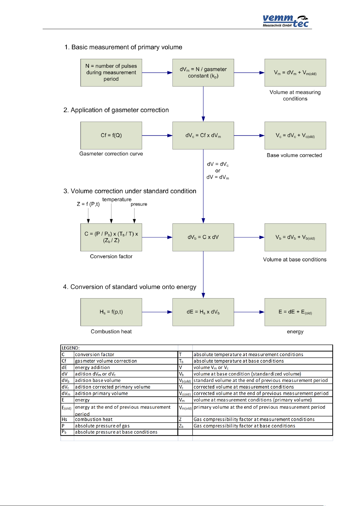
1.2 Function principle
1.2.1 Conversion using the equations of state
The device obtains data on the gas volume via impulses (N) from an LF or HF
sensor located in the gas meter. The volume at the measuring conditions (V) is
calculated from the number of impulses (N) and gas meter constant (kp).
The device obtains other data on the gas from the temperature and pressure
sensors. This data is used to calculate the conversion factor (C) which is influenced
also by: Absolute temperature at base conditions (Tb), absolute pressure at base
conditions (pb) and compressible factor of the gas at base conditions (Zb).
Volume at measuring conditions (operational volume):
Ratio of compressibility factor:
Conversion factor:
4

PTZ-BOX 3.0
Volume at base conditions (standardized volume):
Vb = V * C
The gas compressibility factor expresses the deviation of properties of natural
gas from the properties of an ideal gas. By setting the parameters, it is possible to
choose a specific method for calculation of the compressibility factor according to the
standard (AGA NX-19 mod, AGA8-G1, AGA8-G2, SGERG-88 or AGA8-92DC). A
constant compressibility value can be used for other gases besides natural gas. If the
pressure or temperature value gets out of the limits of the validity of the chosen
standard, the device calculates using a default compressibility value.
The device calculates the gas flow from the impulse frequency on the input in
real time using mathematical filtration from the input signal.
Operational flow:
Q = ∆V / ∆t [m3/h]
Where: ∆V ............................ increment of operational volume
∆t ............................. time between the impulses with an accuracy
of one hundredth of a second
The value of the flow displayed on the converter display is updated every 10
seconds.
Standardized flow:
Qb = C * ∆V / ∆t [m3/h]
1.2.2 Error values of volumes at measuring conditions and volumes
at base conditions
For calculation during error conditions (i.e. in case of a sensor error, deviation of
the parameter value from the working range, or device error), the device has
counters of the error volume at measuring conditions (Vs) and error volume at base
conditions (Vbs). These counters are interconnected with the pertinent counters of
volume at normal conditions.
A detailed description of device behaviour during normal and error conditions is
in paragraph 4.4.
1.2.3 Volume correction at measurement conditions
Device enables to compensate gas meter error according to predefined
correction curve from gas meter test certificate. This function and parameters Vc can
be activated only by the manufacturer or by an accredited service center to ensure
that the used gas meter correction curve as a function of the flowrate Qm is valid
within the working conditions.
The error of measurement is corrected by using the function f(Qm). The
corrected volume is:
Vc = Vm x f(Qm)
5

PTZ-BOX 3.0
Vc
Corrected volume at measurement conditions
Vm
Primary volume
Qm
Primary flowrate
where
Linear interpolation method is used for getting values between calibration
points. The file with correction values is to be inserted into the device by using the
service software [21]. Information about the insertion of a correction curve into the
device is logged in the setup archive.
The principle of the volume calculation is explained in Fig. 1
Condition for use of volume correction.
1. Correction is possible only in the case that the gas meter transmits at least
10 pulses per second which means the use of HF sensors is required.
2. Under Q
correction coefficient given for Q
the correction is not applied and over Q
min
will be used.
max
the value of the
max
1.2.4 Conversion of volume to energy
The device can calculate the energy content from the consumed quantity of
gas. This conversion uses the value of the combustion heat Hs. The calculation is
made with the differences dVb (and dVbs) multiplied by the actual value of the
combustion heat Hs.
dE=Hs x dVb, dEs=Hs x dV
Two counters (energy counter E and error energy counter Es) are dedicated for
measurement in units that can be selected to present the value in MJ, kWh or Btu.
No conversion of the absolute counter value (E or Es) is performed after the change
of measurement units. Following increases are added in the new units.
Principle diagram of energy calculation is drawn at Fig. 1
Combustion heat Hs
To get a correct conversion it is necessary to enter the right value of the
combustion heat and the related conditions. Then the device will make a new
conversion of the relative temperature for the defined relative conditions and the final
value will be used for the energy calculation. In case of the AGA8-92DC method the
combustion heat is not entered as a fixed value but calculated from the gas
composition according to EN ISO 6976. For the other methods the value of Hs
(MJ/m3) must be entered manually and always under the conditions:
combustion temperature/ temperature of gas = 25°C / 0 °C
bs
6
PTZ-BOX 3.0
Fig. 1 Volume and energy calculations - Scheme
7
PTZ-BOX 3.0
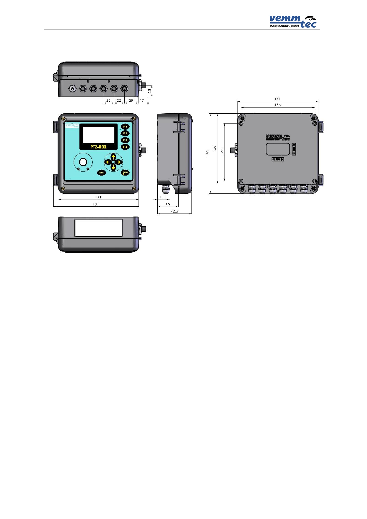
1.3 Device dimensions
Fig. 2 Device dimensions
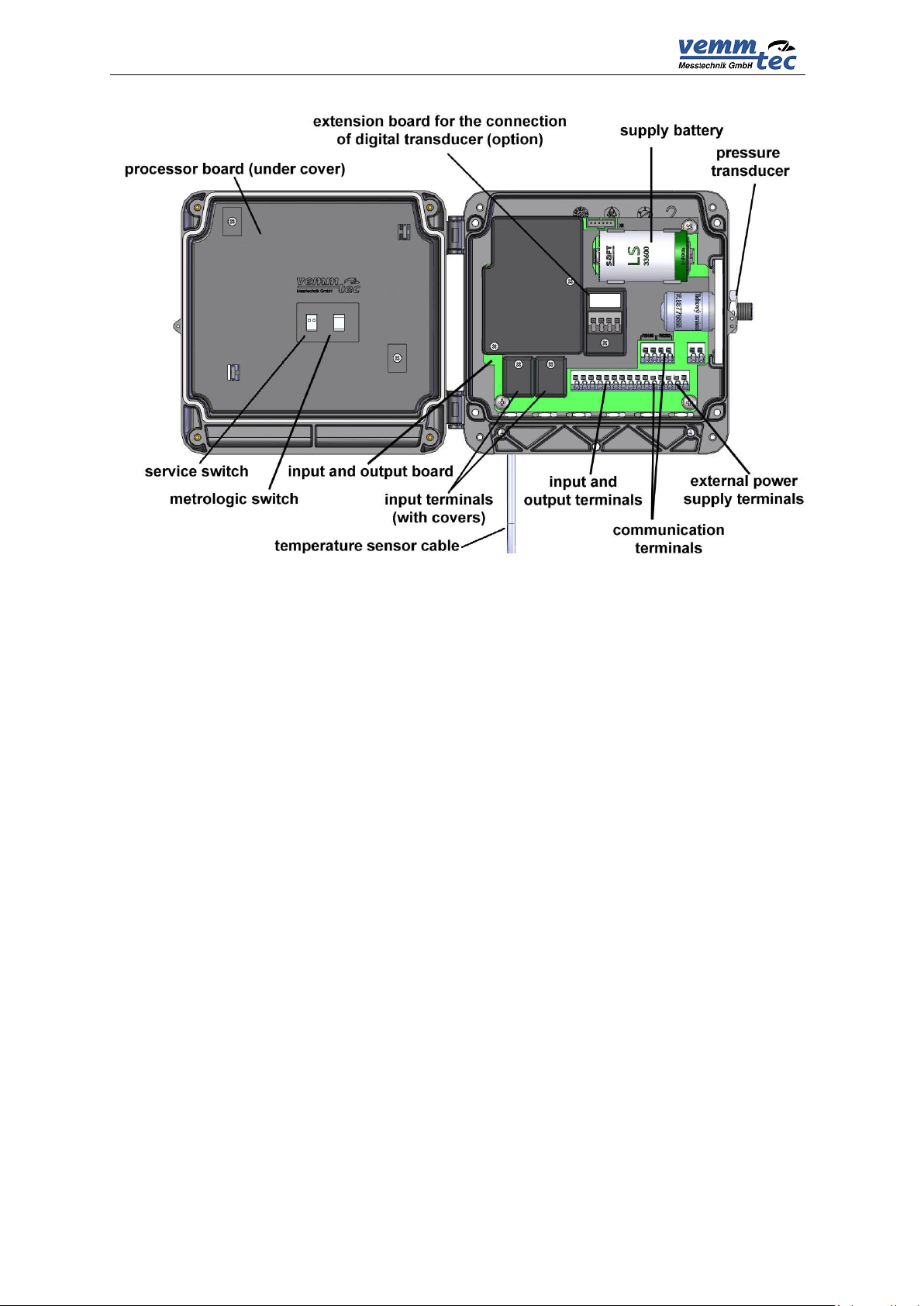
2 Device technical description
2.1 Device architecture
The device’s electronics are laid out on three basic boards.
The bottom part of the casing contains the input/output board with the battery
and back-up battery and terminals for connecting the pressure and temperature
sensors and device inputs and outputs. The connections related to the metrological
function of the converter are protected by covers which are secured with official
seals.
Optionally, the input board can have an extension board (EDT port) for
connecting an additional digital pressure sensor (PA1.1) or digital temperature
sensor (TA1.1). This additional digital sensor communicates with the converter using
the Modbus RTU protocol (via RS-485). More information can be found in chapter 17.
The lid of the housing contains a processor board that is protected by a cover
and secured by an official seal. The board cover has an opening for access to the
service switch. The service switch can be used to enable/disable the setting of the
device parameters using a service SW.
8
PTZ-BOX 3.0
Fig. 3 Main parts of the device
2.2 Power supply
2.2.1 Main supply battery
The device is powered by a built-in (lithium) battery with a voltage of 3.6 V. The
life cycle of the battery depends especially on the configuration of the device, the
frequency of communication, and the time the display is on. The consumed capacity
is calculated during the device’s activity and the capacity decrement is recorded in its
memory. The device will issue an alert to replace the battery 90 days before the
expected discharge (error message E9 – see paragraph 9.4.8.
Standard mode for a life cycle of the main supply battery of more than 5 years:
Archiving period of the data archive 1x per hour
Communication with device 2 min/day
Activating the display 2 min/day
Frequency of input impulses ≤10 Hz
Measuring period 15 s
Ambient temperature 25 °C
If the device is operated with higher consumption than in the defined mode, it
is necessary to count on a more frequent replacement of the battery or use a network
power source.
9

PTZ-BOX 3.0
Replacement of main supply battery is allowed in the hazardous area but
only with recommended type of battery.
To correct the calculation of the remaining battery capacity after
replacement it is necessary to reset the battery calculation with service SW
[22]. In the parameter file, select the hardware module and press the button
„Change battery“.
2.2.2 Replacement of main supply battery
It is advised to disconnect a discharged battery as soon as possible. While the
battery is being replaced, the device does not measure pressure or temperature, but
counts the incoming LF impulses (but does not convert the number of pulses, this will
be performed when the supply battery is connected again) and insures that the real
time clock is running. The data stored in the device archives and parameter settings
will remain.
Discharged batteries are in the hazardous waste category. According to
European directives and other internal directives batteries must not be disposed
together with household waste.
2.2.3 Back-up battery
The battery ensures the back-up of important functions in case of the discharge
or replacement of the supply battery. The back-up battery can be replaced in an
accredited service center after the official and security seal is broken (replacement
cannot be performed in a potentially explosive atmosphere). It is necessary to use
the same type of battery: Only recommended battery type may be used.
Standard mode for a life cycle of the back-up battery of 10 years
Storage temperature 25 °C
Backed-up inputs (DI1 – DI4) not connected or connected contacts
disconnected
Does not depend on the presence of the supply battery
Standard mode for a life cycle of the back-up battery of 4 years
Backed-up inputs (DI1 – DI4) short-circuited
Without powering battery
10
PTZ-BOX 3.0
12 VDC
EEx
P0
DI 1
DO 4
K3 MODULE
DO 1
DO 2
DO 3
P2
6V OUT
DI 3
DI 2
DI 4
POWER
DI1
DI2
DI3
DI4
INPUTS
DO1
DO2
DO3
DO4
OUTPUTS
PTZ-BOX 3.0
RS232
INPUT T
RS485
INPUT P
INT. BUS (optional)
Ex i
POWER
DI1
DI2
DI3
DI4
INPUTS
DO1
DO2
DO3
DO4
OUTPUTS
PTZ-BOX 3.0
RS232
INPUT T
RS485
INPUT P
INT. BUS (optional)
Ex i
=12V
=8V
JBZ-02
EEx
12 Vdc
12 Vdc
Hazardous area Safe area
Safe area
Hazardous area
Self-discharging of batteries
The back-up and supply batteries are lithium type. Their capacity drops due to
self-discharging. The recommended time frame for their replacement is 10 years,
even if the battery was never connected.
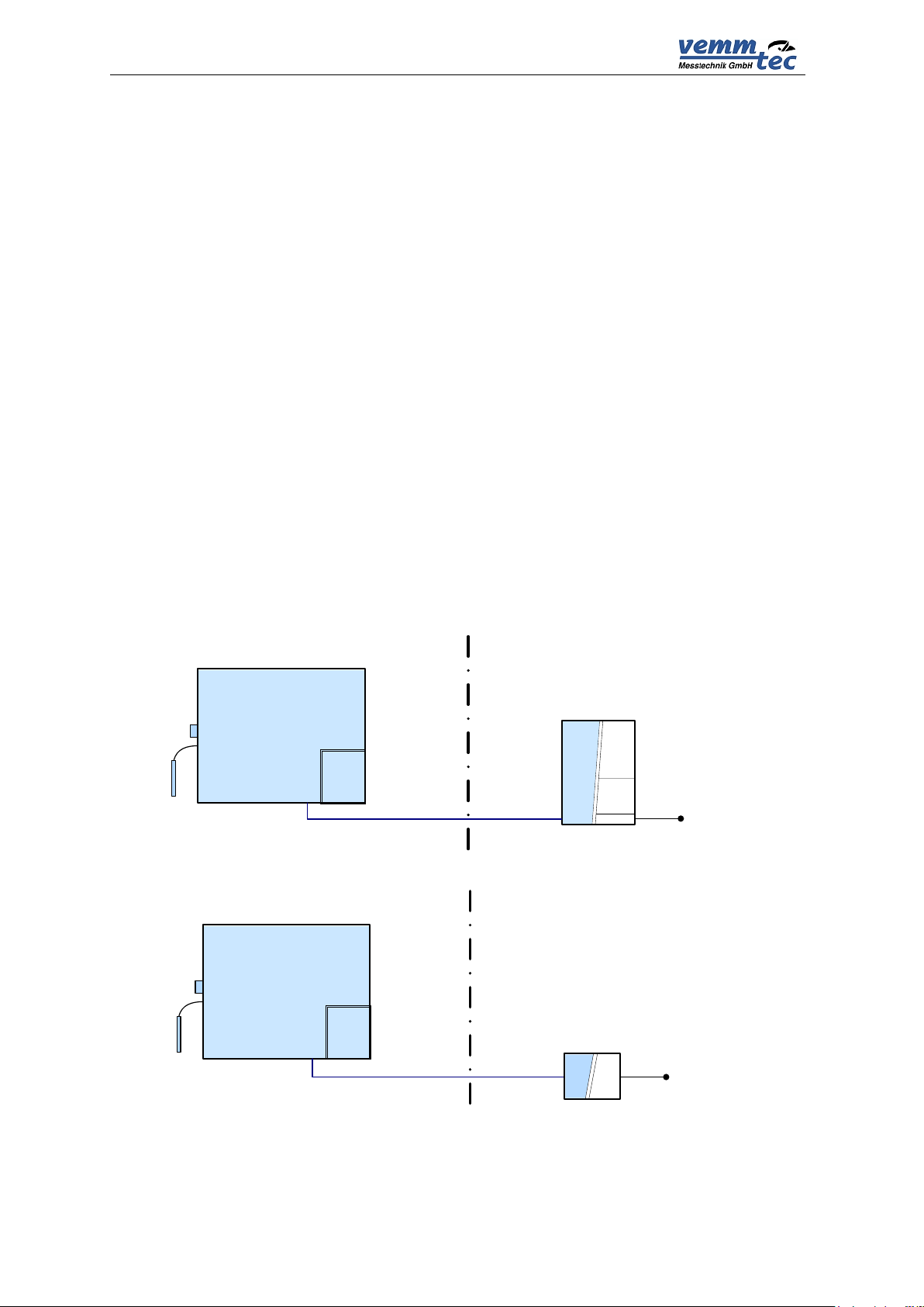
2.2.4 External power supply
Use of an external power supply is required in case of:
- NAMUR HF pulse input
- Binary output
- NAMUR encoder.
External power supply is recommended in case of increased current consumption
like:
- frequent communication (more than once a day),
- frequent LCD displaying
An approved intrinsically-safe power source must be used for the external
power supply. The internal power sources of the communication modules Kx
Modules can be used if no NAMUR sensors are connected.
If a NAMUR sensor is connected: always use an external power source JBZ-02
or JBZ-01.
Fig. 4 Examples of external power supply
11
PTZ-BOX 3.0
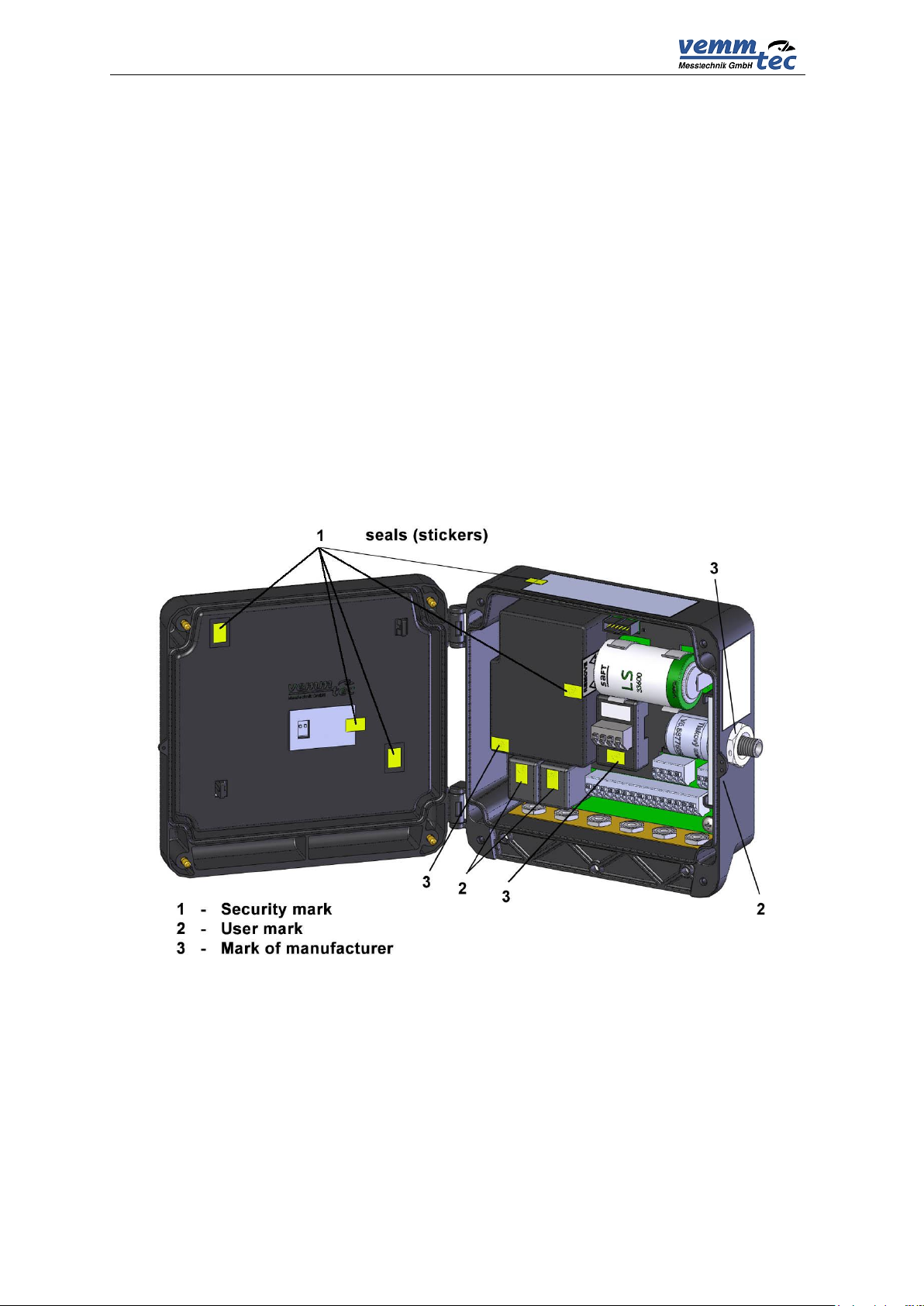
2.3 Security seals
Security seals located on the device indicate the technical condition of the
device regarding unauthorized handling.
Security seal of the manufacturer (metrological seal)
- its design is stipulated by the Approval certificate on the quality management
system for production, output control, and testing pursuant to Enclosure no. 2,
procedure D, ND no. 464/2005 Coll., issued by the Notified Body no. 1383. Such
security mark has the same importance for the user as the so called official seal
according to the Act on Metrology.
In case such a seal is broken, the manufacturer does not guarantee that the
properties of the device are in compliance with the EC Certificate on type verification.
User seal
- control seal of the user (seals) as needed
Seal of the manufacturer
- control seal of manufacturer as needed
Fig. 5 Security marks
12

PTZ-BOX 3.0
2.4 Product label
13

PTZ-BOX 3.0
II 1G Ex ia IIC T4/T3
PTZ-BOX 3.0
Zone 0
The device has been constructed and approved as intrinsically safe. That
means that only approved devices (intrinsically safe devices, consecutive
devices) or so called simple devices complying with the EN 60079-11 standard
and complying with the intrinsically safe parameters listed in the
EC Certificate on type verification [16] can be connected to the device
connectors.
The applicable safety standards must be met when connecting.
3 Safety instructions
3.1 General
The device has been approved according to the guideline 94/9/CE
(2014/34/EU) and an EC certificate on type approval (ATEX) has been issued for its
use in potentially explosive atmospheres. Respecting this guideline is mentioned in
the CE compliance notation.
3.2 Use in potentially explosive atmosphere
Device is fully in compliance with EN 60079-26 ed.2 (see [4]).
Based on the EC certificate in the verification 11 ATEX 0015X, the device can
be operated in potentially explosive atmospheres with a classification of ZONE0.
Indication of the device regarding safety against explosion:
Environment temperature for temperature class T4: -25 °C to +40 °C
Environment temperature for temperature class T3: -25 °C to +70 °C
When connecting a device, it is necessary to consider the electrical
characteristics of the connecting cables and respect the requirements of the
applicable safety standards. Furthermore, it is necessary respect the Special
conditions of use provided these certificates contain them. The parameters of nonexplosiveness of the device are listed in chapter 13.
3.3 Risks of use
Device cabinet is made of polycarbonate. A keypad foil of polystyrene is placed
on the top cover. In some extreme cases electrostatic charge accumulated on
surface of cabinet could cause explosion. To avoid explosion it is strictly
recommended to keep the following rules:
At hazardous the zones device must not be installed at places where
ambient conditions could create an electrostatic charge.
Device may only be cleaned by humid wiper.
14

PTZ-BOX 3.0
Group of gas
Device variant
IIC
IIB
IIA
PTZ-BOX 3.0
yes
yes
yes
1. The device must not be installed or located in an environment with a
potential danger of electrostatic charge of the device casing (e.g. by
flowing air, etc.) Only a damp cloth must be used if the device is being
cleaned, to prevent the creation of electrostatic charge.
2. Only the following types of batteries are allowed to be used in the device:
Main supply battery: Saft LS33600, Backup battery: Saft LS14250.
3.4 Special conditions of use
3.5 Using different groups of gas
Individual variants of device can be used only with certain groups of gas
according to this table.
15

PTZ-BOX 3.0
4 Metrological characteristics
4.1 Temperature measurement
This device uses the PT1000 temperature sensor to measure temperature. The
temperature sensor’s connection is two-wired. The influence of the length and the
characteristics of the cable used are considered during calibration and therefore do
not influence the accuracy of the temperature measuring.
The temperature measuring range is -25 °C to +60 °C. The measuring period is
equal for both the temperature and pressure sensor and it can be custom set at a
range from 1 s to 30 s. The temperature measurement units can be adjusted.
Replacement of the temperature sensor is protected by the security seal of the
manufacturer (metrological seal) and can be performed solely at an Accredited
Service center (ASC).
During device configuration, the user must enter the Default temperature
value. This value will be used for the calculation of compressibility instead of the
measured temperature value in the following cases:
- The value of the measured temperature are out of the measuring range
- An error occurred when measuring the temperature
4.2 Pressure measurement
Pressure measurement is performed by an analogue converter. The converter
contains a piezoresistive silicon sensor with a resistant stainless steel membrane.
The device electronics ensures the correction of non-linearity and the temperature
dependency of the pressure sensor based on the calibration data saved in the device
memory. The measuring range of the pressure converter must be requested by the
customer when ordering the device. The available pressure ranges are listed in
chapter 12.
The measuring period is equal for both the measuring of temperature and
pressure, and can be custom set at a range from 1 to 30 s. The pressure measuring
units can be set.
Replacement of the pressure converter is protected by a security seal of the
manufacturer (metrology mark) and can be performed solely at an Accredited Service
center (ASC).
During device configuration, the user must enter the constant parameter
Default pressure value. This value will be used for the calculation of compressibility
instead of the measured pressure value in the following cases:
- The value of the measured pressure are out of the measuring range
- The device is manufactured without the pressure converter (so called TZ
or T corrector)
- An error occurred when measuring the pressure
16

PTZ-BOX 3.0
Pressure
measuring range
Method
AGA NX-19
mod
SGERG-88
AGA8-G1
AGA8-G2
AGA8-92DC
80 ÷ 520 kPa
-25 ÷ +60 °C
-25 ÷ +60 °C
-25 ÷ +60 °C
-25 ÷ +60 °C
200 ÷ 1000 kPa
N/A
-25 ÷ +60 °C
-25 ÷ +60 °C
-25 ÷ +60 °C
400 ÷ 2000 kPa
N/A
-25 ÷ +60 °C
-25 ÷ +60 °C
-25 ÷ +60 °C
700 ÷ 3500 kPa
N/A
-10 ÷ +60 °C
-10 ÷ +60 °C
-25 ÷ +60 °C
1400 ÷ 7000 kPa
N/A
-10 ÷ +60 °C
-10 ÷ +60 °C
-25 ÷ +60 °C
80 ÷ 1000 kPa
N/A
-25 ÷ +60 °C
-25 ÷ +60 °C
-25 ÷ +60 °C
400 ÷ 7000 kPa
N/A
-10 ÷ +60 °C
-10 ÷ +60 °C
-25 ÷ +60 °C
4.3 Compressibility calculation
4.3.1 PTZ, TZ conversion
The compressibility factor is calculated from the composition of the gas, using
one of the following methods implemented in the device: AGA NX-19-mod, SGERG88, AGA8-G1, AGA8-G2 or AGA8-92DC.
Calculation of the compressible factor is performed in each measuring period. In
the SGERG-88 and AGA8-G1 methods the value of the heating value is entered for
the combustion temperature 25°C / gas temperature 0°C. The service SW contains a
built-in calculator for the conversion of the heat of combustion at different
temperatures.
Due to the required accuracy of the device, the use of the individual methods of
calculation of compressibility is limited by the pressure and temperature ranges
according to the following table:
Table 1 Limitation of standard validity range of compressibility calculation
Note:
Additionally the GOST NX-19 method is applied which is not approved in the
MID certificate. The use of the GOST NX-19 method is limited to a temperature
range from -23°C to +60°C.
Default compressibility
For the set method during each calculation, it is checked whether the measured
pressure and temperature value are in the valid range of the selected method. If
values are outside the valid range, the so called default compressibility is used for
the conversion. The value of the default compressibility must be entered by the user
during device configuration.
4.3.2 PT, T conversion
The device also allows the setting of the ratio of compressibility factors (K) as a
fixed constant. The range of the entered constant is not limited.
17
PTZ-BOX 3.0
Vm
Primary volume counter (Actual volume)
Vc
Corrected volume counter (volume corrected based on gas meter
correction curve)
V
Volume Vm or Vc
Vs
Counter of the actual volume under error conditions (error actual
volume)
Vb
Counter of volume at base conditions (standardized volume)
Vbs
Counter of standardized volume under error conditions
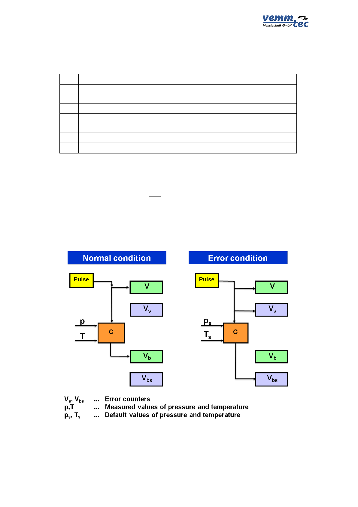
4.4 Volume measurement and calculation
For measurement and volume calculation the following counters are used for
each channel.
4.4.1 Operation at error conditions
In case of error conditions, the device will count the actual value as well in the
counter of the actual volume (V) and in the counter of the error volume at measuring
conditions (Vs). The values of the volumes at base condition (Vb) will stop being
counted in the counter of the volume at base conditions (Vb), and will calculate from
the default values of pressure or temperature and will be stored in the counter of the
error volume at base conditions (Vbs). During this condition, the values are not stored
in the counter of volume at base conditions (Vb).
Fig. 6 Storing impulses in counters
18
PTZ-BOX 3.0
If a default compressibility is used during the calculation (when temperature or
pressure are out of the valid range of the compressibility calculation formula) (see
article 4.3.1), whereas pressure or temperature are not outside the measuring range;
the converted volume is stored in the error counter.
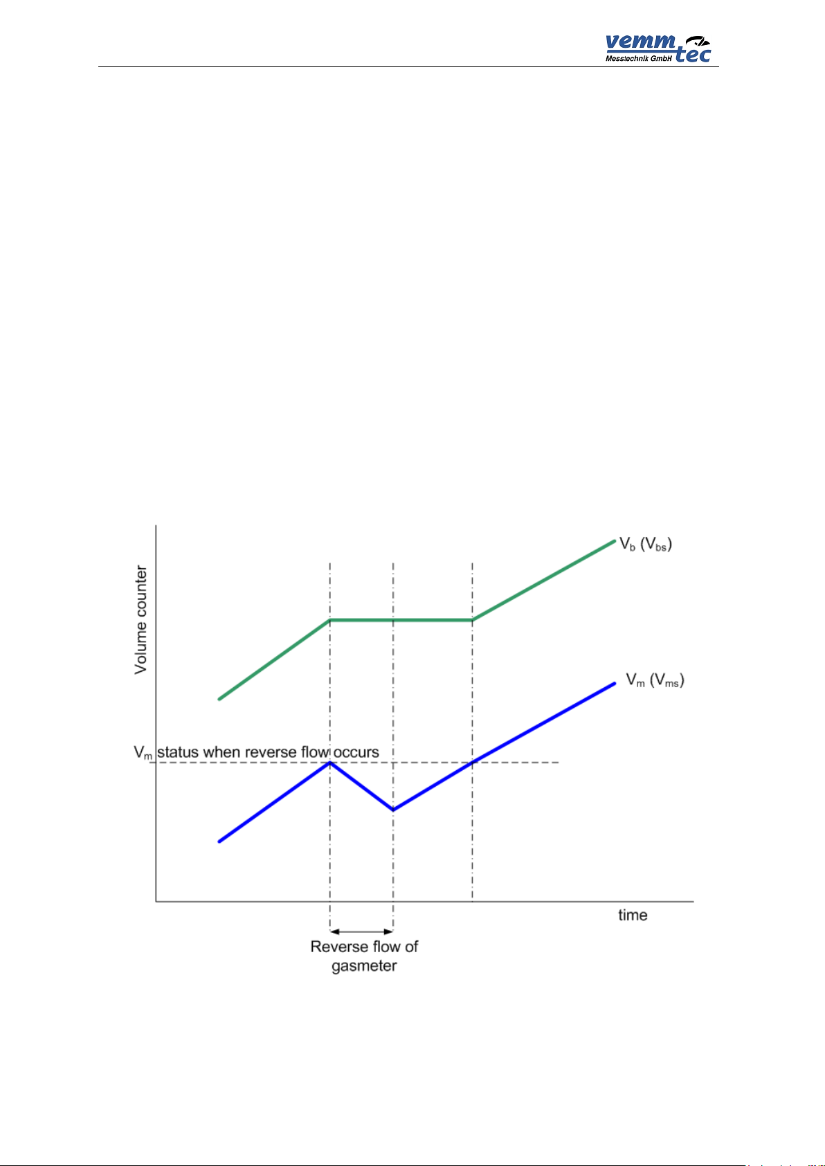
4.4.2 Recognition of a changing gas flow direction
Flow direction detection is enabled for gas meters equipped with two phases
shifted LF sensors or encoders. Corrector evaluates gas flowrate respecting direction
changes (Pic. 7) under following terms:
- If primary volume additions are positive: volume processing is made by
standard procedure (for example increasing of Vm and Vb, or Vms and Vbs).
- If gas flow direction is changed device will fix the value of primary volume
counter at the moment of turn. When gas flows back only primary
volume Vm (or Vms) is updated. The other counters are frozen.
- After returning back to the correct direction counting will get blocked out
into appropriate counters (Vb, Vbs) only after reaching level of primary
volume where reversed flow was started up. Primary volume counter is
equivalent to gas meter counter all the time.
Fig. 7 Processing of volumes during reversed flow
19

PTZ-BOX 3.0
Input
Binary
contact
Binary
NAMUR
LF
impulse
HF
impulse
NAMUR
encoder
DI1 √ √
√ √ √
DI2 √ √
√ √ -
DI3 √ - √ - - DI4 √ - √ -
-
5 Inputs and outputs
5.1 Inputs
A total of 4 digital inputs marked as DI1 to DI4 can be connected to the device.
The inputs are provided at the terminal board inside the device. The digital inputs can
be adjusted as a binary or as a LF impulse by using the service SW. The DI1 and DI2
can also be set as HF NAMUR impulse or as a binary NAMUR type. In devices with
FW ver. 4.xx input DI1 may be setup also for connection with NAMUR encoder.
Table 2 Digital inputs setting options
5.1.1 LF impulse inputs
Serves to read impulses from a gas meter. The flow measuring function can be
chosen for these inputs. The back-up battery ensures preservation of counters’
conditions and reading the impulses of the LF inputs also in case of the discharge or
replacement of the supply battery. After connection of the supply battery, the
impulses read during missing voltage of the supply battery are added to the error
counters. The LF impulse input is, on the DI1 and DI2 inputs, connected between the
terminals LF+ and LF- (see Fig. 8).
Changing measuring units, setting the gas meter constant
The measuring units of the impulse inputs can be changed using the service
SW [22]. The conversion constants of the gas meter and S/N of gas meter can be set
using the service SW as well, as also directly from the device keyboard. When
setting the value of the gas meter constant, only decimal folds or fractions in range
from 0.01 to 100 are expected.
Number of places of counters of LF impulse inputs
In the case of LF impulse inputs, the counter works with 9 valid digits, the gas
meter constant influences the size of the maximum number from 9 999 999.99 (for
constant = 0.01) to 99 999 999 900 (for constant = 100).
5.1.2 HF impulse inputs (NAMUR)
The inputs DI1 and DI2 can be configured for processing HF NAMUR impulses.
Due to the fact that these sensors require a supply voltage higher than the voltage of
the supply battery of the device, the converter must have an external supply voltage
higher than 7 Vdc (e.g. from JBZ-02) for the registration and processing of HF
impulses.
The flow measuring function can be chosen for these inputs. The back-up
battery ensures the preservation of counters’ conditions in case of a failing external
power supply even in the case of discharge or replacement of the supply battery, but
20

PTZ-BOX 3.0
it does in this case not count the impulses. The terminals for the HF NAMUR inputs
are marked HF+ and HF- (see Fig. 8).
Changing measuring units, setting the gas meter constant
The impulse inputs measuring units and the gas meter constant can be
adjusted using the service SW. The gas meter constant and S/N of gas meter can
be also set from the device keyboard.
Number of places of counters of the HF impulse inputs
In the case of HF impulse inputs, the counter works with 9 digit places.
5.1.3 Connection with gas meter via encoder
Gasmeter can be connected with corrector via an NAMUR encoder. In this case
the digital value of the gas meter counter is transferred into EVC. The use of an
encoder is approved for metrological use by the EC- MID type approval.
NAMUR Encoder
No special HW is required for the use of a NAMUR encoder. The only condition
for NAMUR encoder data processing is the use of an IS external power supply
(JBZ-02 or JBZ-01).
NAMUR Encoder input
Connection between EVC and encoder is made with a shielded two wire cable.
The NAMUR encoder can only be connected via the digital input DI1. Terminals for
the encoder are the same as for HF pulse inputs marked HF+ and HF- (correct signal
polarity is important.). NAMUR encoder connection must be setup in the EVC
parameters with service SW [22].
5.1.3.1 Device specification with encoder
Data from an encoder are transferred into EVC via shielded two wires cable.
Together with the absolute value of gas meter counter there are transferred other
additional data like S/N, gas meter constant, nine positions for counter overturning).
These additional data are read out with service SW [22] usable at device
configuration.
In case of an error in the communication between EVC and encoder then an
asterisk symbol “ * “ after the actual primary volume. Manual setup of primary volume
counter Vm is not allowed at encoder input.
Installation and replacement of gas meter
When the actual counter value of the gas meter is transferred into the EVC after
connection of the encoder and the EVC a big difference might occur at the primary
volume Vm. To prevent against affection of base volume Vb (Vbs) it is necessary to
keep following instruction:
1. In service SW [22]: display device parameters; select subject „Hardware“
and the push button „Change gas meter“. During encoder exchange the
processing of the primary volume from the gas meter will be stopped.
(Follow further follow instructions on the PC display).
2. Physically connect the encoder to the EVC.
21

PTZ-BOX 3.0
3. After connection of the encoder finish installation/exchange with OK button.
During installation/exchange (point 1) no differences are added to the applicable
counters which are marked on display with exclamation mark. If point 3 is not finished
by one hour exchange procedure will be closed automatically at service SW.
5.1.4 Binary inputs
These inputs monitor the input signals with the option of an evaluation of the
condition “connected” (i.e. log. 0) or “disconnected” (log. 1). The device allows
evaluation of binary inputs from no-potential outputs (reed contact or open collector –
these signals are on DI1 and DI2 inputs connected to terminals LF+, LF-) or from
NAMUR sensors (DI1 and DI2 inputs, terminals HF+, HF-). NAMUR sensors require
an external power supply of the converter higher than 7 V (JBZ-01 or JBZ-02).
By setting the parameter, the user can choose the display of the actual values
on the display, storing the changes of these inputs in the archive; display the
headline for condition log. 0 and log. 1, and active signal level.
Fig. 8 Inputs and outputs terminals
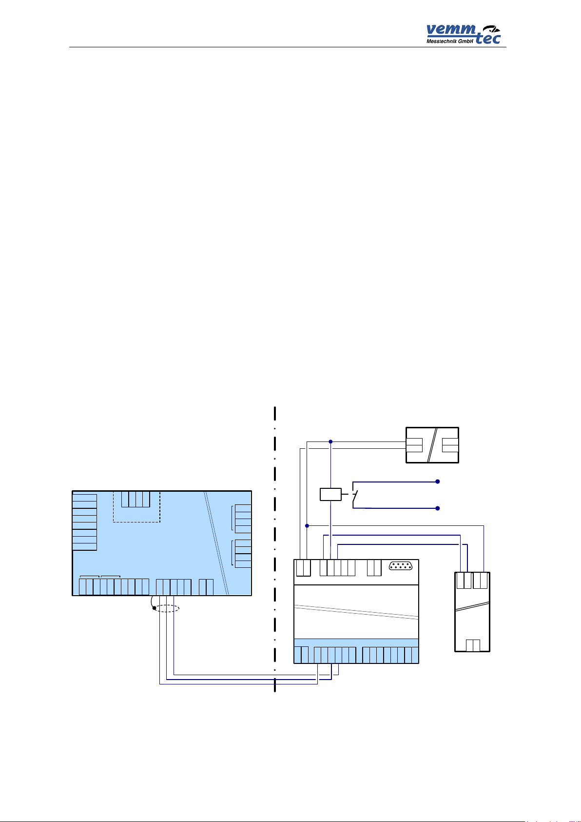
5.2 Outputs
The device has 4 digital outputs DO1 to DO4 which can be configured as
binary, impulse, or data. A data output serves the CL1 analogue output module (4-20
mA) which should be connected to this output.
The outputs can be controlled by the device using calculation equations
entered by the user in the device parameters (for example, it is possible to generate
outputs according to the gas flow, indication of alarm condition, exceeding the set
limits of pressure or temperature, etc.).
22
PTZ-BOX 3.0
INPUTS
POWER
GND
+
HF+
LFHF-
LF+
HF+
-+-
+
PTZ-BOX 3.0
GND1
CTS
RxD
TxD
RS232
Ex i
OUTPUTS
DO1
DO2
DO3
DO4
GND
LF+
LFHF-
DI1
DI2
DI3 DI4
1. channel (analog)
Pt1000
Pt1000
GND
Vce
UT
UP-
UP+
1W
GND1
U1+
D1 -
D1+
RS485
INT. BUS RS485
(optional)
U+
D-
D+
GND
K3 MODULE
P2-RS232
1
9
5
6
Um = 250 V
DIGITAL OUTPUTS
DO3
D -
DO2
DO1
GND
DIGITAL INPUTS
GNDU+DI1
DI2
DI3
DI4
P0 – RS485
GNDU+D-D+GND
U+
D-
D+
6V OUT
GND
U+
DO4
D +
+
GND
12V
P2-RS485
DIN 12V
4-20mA
-
+
CL-1
GNDDIGND
+
+
-
~
~
12VDC
230VAC
U2 U4
230 V/50Hz
Hazardous area
Safe area
relay
pulse | binary
output (DO1)
current output
4-20mA
(DO2)
The device structure allows the generation of outputs even when the device is
powered solely by the battery with no effect on the battery life cycle. The outputs are
“open collector” type and are not galvanic separated. All four outputs have a joint
GND conductor.
The outputs are intrinsically safe, thus when connecting standard devices, the
devices must be connected via a safety barrier (e.g. K3 Module, see
Fig. 9).
Impulse outputs
The impulse outputs have adjustable width and impulse periods in folds of 0.1 s.
Collection of impulses for these outputs can reach max. 65535 pulses. An output
constant can also be configured in the setting equation of the output parameter.
Binary outputs
Output terminals are according to the setting and status in the connected or
disconnected state. In the resting state, the output terminals are disconnected
(condition log.1).
Data output
The digital output configured as a data output serves for communication with
the CL-1 module. An analogue output 4-20 mA can be realized using this module.
Using the calculation equations, the value of the output can be parameterized as
proportional to pressure, flow, daily consumption, etc. The CL-1 module must be
connected to the converter via a safety barrier (K3 module).
Fig. 9 Example of an impulse (binary) output and current output scheme
23

PTZ-BOX 3.0
6 Communication with the PTZ-BOX 3.0
For communication with other devices, the PTZ-BOX 3.0 is equipped with one
communication channel with three possible communication interfaces. Either the
communication interface RS-232 or the RS-485 can be used for connection with a
superior system. The optical interface is designed as temporarily connection for
readout or device configuration.
In the current firmware version, the device is equipped with several
communication protocols. The device is prepared for extension by other protocols as
required by the customer. The standardly implemented protocols are VTC and
MODBUS RTU. Pre-set communication protocol is the same for all communication
interfaces. It is possible to change communication speed for fixed connections and
for optical interface independently.
The VTC protocol is the native protocol of the device. A complete set of
functions realized in the device is available. The service SW [22] solely uses this
protocol – in case it is necessary to switch to other link level, the VTC protocol is only
wrapped in one other link level (a so called “a tunnel”). The VTC protocol is used as
the only one for loading firmware (protected by the metrology seal).
The communication circuits are galvanic separated from other device circuits.
Because of the galvanic separation, the communication circuits must be powered
from outside, from a connected device (CTS signal in case of the RS-232 interface
and U1+ in case of the RS-485 interface).
6.1 RS-232 and RS-485 interfaces
Both interfaces are brought out to the internal terminal board and, although they
are simultaneously functioning, only one of these interfaces can be used (connected)
for communication at a time. Because both of the interfaces are intrinsically safe, it is
necessary during installation to separate the device in a potentially explosive
environment from the connected common device (computer, modem, etc.) by a
consecutive device (Sx Module, Kx Module, MTL 5051 etc.), or use a device with an
intrinsically safe design.
The communication speed of the interface (the speed is joint for both interfaces)
and the communication protocol can be set in the device parameters.
Communication via modem controlled by AT commands
Basic setting features of a modem for the correct cooperation with the device:
Sending answer (ATQ0)
Long format of the sent answers (ATV1)
Echo disabled (ATE0)
Automatic pickup (ATS0=1)
Set firmly serial port communication speed of the modem (e.g. for speed
38400 Bd is command AT+IPR=38400)
Ensure presence of power feeding on clamp DSR of the modem (by
command AT&S0). Clamp DSR is connected with CTS clamp of device.
More detailed information must be found in the manual of the used modem.
24
PTZ-BOX 3.0
INPUTS
POWER
GND
+
HF+
LFHF-
LF+
HF+
-+-
+
PTZ-BOX 3.0
GND1
CTS
RxD
TxD
RS232
Ex i
OUTPUTS
DO1
DO2
DO3
DO4
GND
LF+
LFHF-
DI1
DI2
DI3 DI4
1. channel (analog)
Pt1000
Pt1000
GND
Vce
UT
UP-
UP+
1W
GND1
U1+
D1 -
D1+
RS485
INT. BUS RS485
(optional)
U+
D-
D+
GND
K3 MODULE
P2-RS232
1
9
5
6
Um = 250 V
DIGITAL OUTPUTS
DO3
D -
DO2
DO1
GND
DIGITAL INPUTS
GNDU+DI1
DI2
DI3
DI4
P0 – RS485
GNDU+D-D+GND
U+
D-
D+
6V OUT
GND
U+
DO4
D +
+
GND
12V
P2-RS485
12 Vdc
RS485
Hazardous area
Safe area
INPUTS
POWER
GND
+
HF+
LFHF-
LF+
HF+
-+-
+
PTZ-BOX 3.0
GND1
CTS
RxD
TxD
RS232
Ex i
OUTPUTS
DO1
DO2
DO3
DO4
GND
LF+
LFHF-
DI1
DI2
DI3 DI4
1. channel (analog)
Pt1000
Pt1000
GND
Vce
UT
UP-
UP+
1W
GND1
U1+
D1 -
D1+
RS485
INT. BUS RS485
(optional)
U+
D-
D+
GND
Switches OFF ON meaning
SW1a X --- other modes
SW1b X --- 5V output
SW2a RS232 RS422 output interface
SW2b RS422 RS232 output interface
MTL 5051 setting
20÷30 Vdc
RS-232
3
4
6
5
2
1
RS-232
Rx 12
COM 11
Tx 10
Tx+ 9
Rx+ 8
Rx 7
RS-422
Vs+ 14
Vs- 13
MTL 5051
Ex i
Common
5V or 12V
Tx
Rx
HAZARDOUS AREA
SAFE AREA
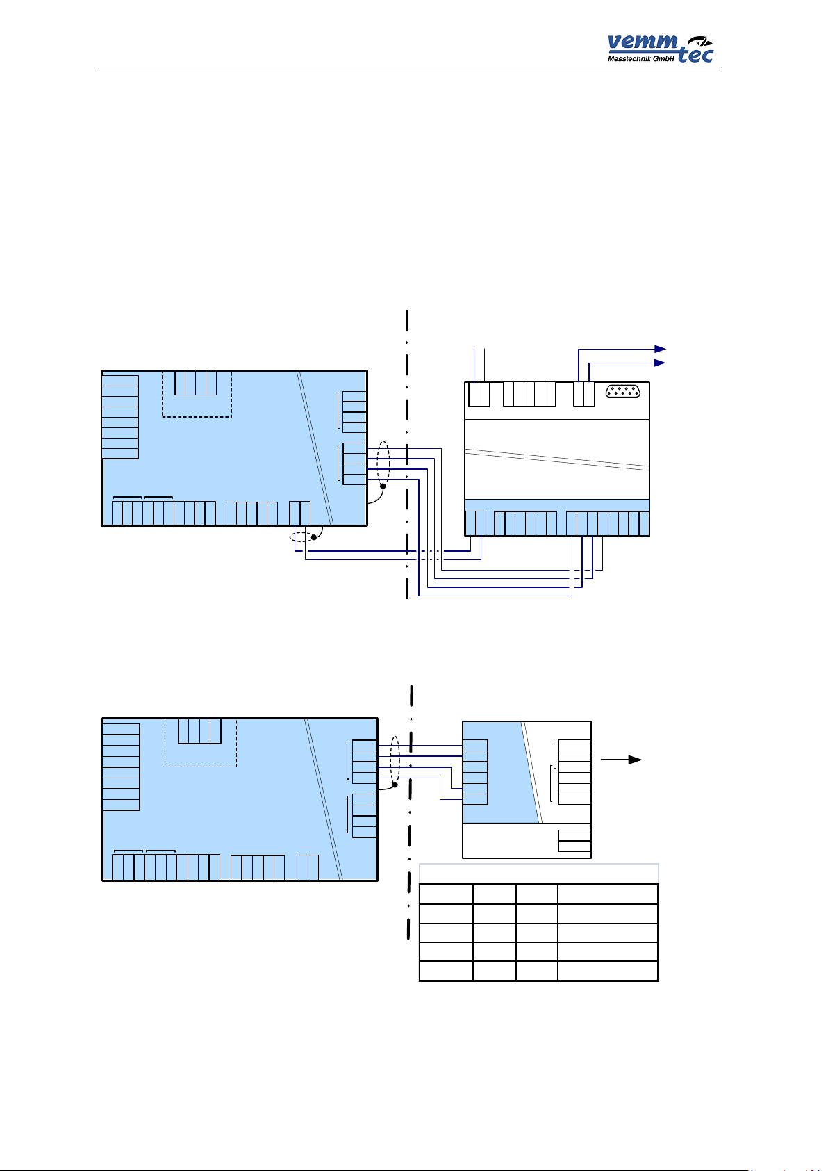
Communication with GSM and GPRS modems
For the purpose of diagnostics during the modem installation, the device has
the option of displaying the information from the modem on the presence and
connection to a GSM network, and further information on the signal strength
measured by the modem. In the case of a GPRS connection, it is possible to display
the IP address.
Compatibility with the Siemens MC35, MC39 modem is necessary for correct
function in AT commands:
AT+CREG?, AT+CSQ?, AT+CGDCONT and AT^SGAUTH+CGDCONT.
Note: Communication output from K3 Module can be RS-485 or RS-232
Fig. 10 Safety separation of communication using module K3 Module for RS-485
Note: Communication output from MTL5051 can be RS-232 or RS-422
Fig. 11 Safety separation of RS-232 communication via separator MTL 5051
25
 Loading...