

Vemmio MT-100 User Manual
WWW.VEMMIO.COM
motion
mini
sensor
MODEL: MT-100
V1.0
INTRODUCTION
Thank you for c hoosing Vemmio. We welcome yo u in our customer society.
Motion Mini Sensor provides accurate motio n and illumination
level detec tion. When inte grated with your c ontroller - wirele ss
notificat ions, low battery ale rts, custom automa tion scenarios
based on bot h light and motion trigge rs become available. For
example, w hen motion is d etected, t he controlle r will send an
alert to any sm artphon e, set off a n alarm or trig ger a lighting
scene. Th e sensor works w ith any Z-Wave-certifie d controller.
PACKAGE CONTENTS:
• user manual
• sensor
• raw plug
• adhesive tape.
KE Y FE ATU RE S
Ultra smar t and simple d esign – beco mes part of yo ur home
decoration
Easy and qu ick installatio n
Uses motion and illumination sensors
Low-energy use
Illuminatio n measuremen t up to 8500 lux.
SPECIFICATION
Wireless standard Z-Wa ve Plu s
Frequency 868.4 0 MHz
Network range 30 m line of sigh t
Operating temperature 0°C ~ 40 °C
Illumination measurement
range
0 ~ 8500 lux
Movement Sensor Measurement range
6 m
Battery CR123A 3V
Battery >2 years, low powe r indication
BAT TER Y
INSTALLATION
When the dev ice repor ts the
low batter y message, th e user
should repl ace the battery to
new one. Th e battery t ype is
CR123A, 3V.
To open the top cover si mply
turn and lif t it.
INSTALLATION
The Z-Wave button, lo cated nex t to the batter y can add , remove, reset o r associate the se nsor to Z-Wave network.
ADDING TH E DEVICE INTO THE Z-WAVE NETWORK
FIRST INCLUSION
Bring the Mot ion Mini Sens or within direct range of yo ur controller. Careful ly turn and lif t the cover of yo ur Motion Mini
Sensor to ac cess the bat tery. Follow th e instruc tions for your
Z-Wave certified cont roller to enter in clusion mod e. When
prompted by t he controller, power o n the device, ( jus t remove
the plastic p ull-tab from th e battery s lot of the devic e). Press
quickly the Z-Wave butto n 3 times. The se nsor should b e included in 5 second s. You will see the L ED light fast flash indica ting
Motion Mini S ensor is inclu ded to Z-Wave network and it s hould
appear on co ntroller’s devi ce list
INCLUSION*
Bring the Mot ion Mini Sensor within dire ct range of your controller. Remove the to p cover from th e device by turni ng and
lifting it . Follow the ins tructio ns for your Z-Wave certif ied
controller to e nter inclusion mo de. When promp ted by the controller, press qui ckly one of the Z-wave button 3 ti mes in a row.
The senso r should be include d in 5 seconds. The se nsor should
appear on yo ur controller ’s device list.
*Please note : Always exclude a Z-wave pro duct before t rying
to add it to a Z-Wave network .
EXCLUSIO N
Bring the Mot ion Mini Sensor wit hin direct range of you r controller. Remove the to p cover from the device by turn ing and
lifting it . Follow the inst ructions f or your Z-Wave certified c ontroller to enter e xclusion mo de. When pr ompted by the c ontroller, press th e Z-wave button quickl y 3 times in a row. The
LED indicato r will flash slowly indic ating successf ul exclusion.
The senso r should disapp ear from your contr oller’s device list .
If the first a ttempt is unsuccessf ul, please repeat the p rocess
following all steps c arefully.
Make sure all se nsors of the d evice have bee n successf ully
added to your c ontroller. If not , please run e xclusion/ inclusion proce dure.
ASSOCIATION
Have Z-Wave Controller ente r association mo de.
Pressing tam per key three time s within 1.5 s econds will enter
association mode.
Group IDMaxi-
mum
Nodes
Description
1 4 GROUP 1 is lifel ine service th at assigned to
Sensor (M otion detector) s tatus – Open /
Close. It ena bles the senso r to send repor ts
and reading s to Z-Wave Controller or ZWave Gateway whe never the senso r is triggered. This G roup Suppo rts:
• NOTI FICATI ON_ REPOR T_V4
• SENSOR_BINARY_REPORT_V2
• SENSOR_MULTILEVEL_REPORT_V7
• BATTERY_REPORT DEVICE_RESET_LO-
CALLY_NOTIFICATION
2 4 GROUP 2 allow s for sending con trol com-
mands to asso ciated devices su ch as relay
module, lig hting, etc. T his association g roup
is configur ed through the a dvanced para meters no. 2, 3 , 5 and 8. This G roup Suppor ts:
• BASIC_SE T
3 4 GROUP 3 allow s for Send Notif ication to
associated d evices in this gro up. This Group
Supports:
• NOTI FICATI ON_ REPOR T_V4
4 4 GROUP 4 allow s for Send Sen sor Binary
Report to as sociated device s in this group.
This Group S upports:
• SENSOR_BINARY_REPORT_V2
FACTORY RESET
Make sure the Mo tion Mini Sen sor is powere d on, then op en
the cover and p ress and hold the Z-Wave butto n for at least 10
seconds un til the LED indicator flash es once (it may then flash
5 times to indic ate the device is no longer p art of Z-Wave network). Relea se the button .
Please note: A ll previously recorde d activity and cus tom settings will be e rased from the d evice’s memory.
TROUBLESHO OTING TIPS.
If you are unabl e to include the M otion Mini Sen sor to your controller, please tr y one of the follo wing:
• Bring the M otion Mini Sen sor closer to yo ur Z-Wave controller.
• Once in incl usion mode, pres s and release the Z-Wave button
quickly 6-7 times to e nsure the comm and has gone thr ough.
• Put your c ontroller into exclusion m ode. Press the Z-Wave button quickly 3 tim es, and the n try addin g it to your netw ork again.
PHYSICAL INSTALLATION
Choosing a Suitable Location
a. The recomm ended mounti ng height is 2 m
b. T he recommen ded distance f rom the door is wi thin 4.5 m
c. Do not let t he device face th e window or the su nlight.
The Motion M ini Sensor will detect m otion up to 6 meters depending on mounting location an d sensitivity settings.
MOUNTING
There are 2 way s to mount the Mini Sens or on the wall, ceiling ,
or in the corne r of a room:
1. U se the suppli ed raw plug to fix t he mountin g bracket to
flat surfa ce of your choice. Car efully insert the s ensor to the
mounting br acket. Positi on the sens or by directin g it to the
part of the ro om you wish to moni tor.
2. U se supplied adhesive t ape to fix the mounting br acket to a
clean flat sur face of your choice. C arefully insert the s ensor
to the mountin g bracket. Posi tion the senso r by directing it to
the part of t he room you wish to mo nitor.
Over the Air Fi rmware Update
The device su pports the Z-Wave firmware up date via OTA. Let
the controll er into the firm ware update mo de, and then press
the Z-Wave button once to s tart the update. Af ter completing
the firmwar e download , LED will star t flashing eve ry 0.5 s econd. Durin g this time, pl ease don’t rem ove the batte ry, otherwise it will cau se the firmware failure , and the device will stop
functio ning. Afte r LED stops fla shing, it is re commende d that
user power s up the device . Caution: Af ter batter y removal ,
please wait a bout 30 seco nds, and then r e-install the b attery.
Supported Command Classes:
COMMAND_CLASS_ASSOCIATION
COMMAND_CLASS_ASSOCIATION_GRP_INFO
COMMAND_CLASS_BATTERY
COMMAND_CLASS_CONFIGURATION
COMMAND_CLASS_DEVICE_RESET_LOCALLY
COMMAND_CLASS_MANUFACTURER_SPECIFIC
COMMAND_CLASS_NOTIFICATION
COMMAND_CLASS_POWERLEVEL
COMMAND_CLASS_SENSOR_BINARY
COMMAND_CLASS_VERSION
COMMAND_CLASS_WAKE_UP
LED INDICATION
LED
Color
Indication Status
Red Flashes 5
times(1s
Interval)
Powered on an d not included i n Z-Wave
Network
Flashes 5
times(500
ms Interval)
Press the Z- Wave button 3 t imes - including the sens or to a Z-Wave network
Flashes 5
times(300
ms Interval)
Powered on an d already inclu ded in a
Z-Wave network
Flashes 1
once
1. Press the Z-Wave but ton for 10 second s
long time - fa ctory rese t is perform ed
2. Movemen t detection
WAKEUP MOTION D ETECTOR
You can press the b utton once to wake up the d evice and send
wakeup notif ication to contro ller -the LED will flas h once.
ADVANCED CONFIGURATION
The followi ng information is fo r someone that ha s some experience in sett ing up a Z-Wave system or som eone that has computer sof tware runn ing a Z-Wave controller or Z-Wave Gateway. Please get fa miliar with software of Z-Wave contro ller or
Z-Wave Gateway before get ting started .
NO Name Deff Description
1 Sensitiv-
ity Level
Setting
12
Valid Values: (8 – 255), Prm . Size: 1 byte
This parame ter defines th e sensitivity
of PIR detecto r, it is recommended t o
test the dete ctor with movem ents from
a farthe st end of the covera ge area at
first time of u se. If movement s cannot
be detecte d sensitively, simp ly adjust
the sensitiv ity level with th is parameter.
This Parame ter can be confi gured with
the value of 8 th rough 255, wher e 8
means high sensitivity and 255 means
lowest sensitivity.
2 On/Off
Duration
30
Valid Values (5 – 60 0), Unit: Secon d,
Prm. Size: 2 byt es
This parame ter can be determ ined how
long the ass ociated devices s hould stay
ON status . For instance , this parameter
is set to 30(s econd), the PIR d etector
will send a BA SIC_S ET Command to a n
associated d evice with value b asic set
level if PIR dete ctor is trigger ed and
the associa ted device will be tu rned on
30(sec ond) before it is tu rned off. This
Parameter va lue must be larg e than Parameter 6#. If us er set this param eter to
default by Co nfigure CC, th e parameter
#6 will be set to de fault value
3 Basic
Set
Level
255
Valid Values: (0 – 99), Un it: Percent,
Prm. Size: 1 byt e 0 – OFF , 255 - ON
Basic Set Com mand will be sent w here
contains a val ue when PIR detec tor is
triggered , the receiver wi ll take it for
consideration; for instance, if a lamp
module is rec eived the Basic S et Command of which v alue is decisive as to
how bright of di m level of lamp modu le
shall be. Thi s Parameter is use d to some
associated devices
4 PIR De-
tecting
Function
Enabled/
Disabled
255
Valid Values: 0 – Disa ble PIR, 255 –
Enable PIR
This parame ter can be enabl ed or
disabled th e PIR detector de tecting
function.
5 Ambient
illumination Lux
Level
100
Valid Values: (0 – 10 00), Unit: Lux, P rm.
Size: 2 bytes
This parame ter can be set a lux l evel
value which d etermines whe n the light
sensor is ac tivated. If the a mbient illumination level falls below this value
and a perso n moves across or w ithin the
detected a rea , PIR detector w ill send a
Z-Wave ON command(i.e . BASIC_ SET
(value = param eter 3) to an associ ated
device and a ctivate i
6 Re-
trigger
Interval
Setting
8
Valid Values: (0 – 8), Uni t: Second , Prm .
Size: 1 bytes
This Parame ter can be used to a djust
the interva l of being re-trig gered after
the PIR detec tor has been trig gered.
This Parame ter value must b e less than
Parameter 2 #. If user set this para meter
to default by Co nfigure CC, th e parameter #2 will be se t to default value .
WWW.VEMMIO.COM
7 Light
Sensor
Polling
Interva
Time
180
Valid Values: (60 – 36 000), Unit: S econd, Prm. Si ze: 2 bytes
This Parame ter can be set the l ight sensor measure ambient illumination level
interval tim e. NOTE: This Valu e Must Be
less than Wakeu p Interval Time
8 Lux
Level
Function
Enable
0
Valid Values: (0 or 1), Pr m. Size: 1 bytes
If this param eter is set to ‘1’, and when
Lux level les s than the value de fine by
parameter #5 , PIR detector wi ll send
a BASIC _SET co mmand frame (i .e.
BASIC _SET (val ue = parameter 3) to a n
associated d evice and acti vate it. If Lux
Level greater t han the value def ine by
parameter #5 , PIR detector wi ll not send
a BASIC _SET co mmand frame.
9 Ambient
illumination Lux
Level
Report
100
Valid Values: (0 – 255), Un it: Lux, Prm.
Size: 2 bytes
This parame ter defines by h ow much
Lux Level mus t change, in lux , to be
reporte d to the main controll er.
10 L ed
Flash
Enable
1
Valid Values: (0 or 1), Pr m. Size: 1 byte
This parame ter defines th e Led on/off
enable. If th is parameter is se t to ‘1’, the
led blink will b e enabled, the l ed will
flash once wh en motion sens or detect a
movement. Otherwise, the led will
be turned of f always.
MULTILEVEL SENSOR
The Motion M ini Sensor supp orts ambien t luminance measu rement, the s cale is LUX. The set tings of luminance s ensor measurement are lis ted in Advance d Configurati on.
WAKEUP COMMAND CLASS
The motion d etector st ays in sleep st atus for the ma jority of
time in order to co nserve bat tery life.
The minimum w akeup interval is 3 00s
The maximu m wakeup interva l is 16,777,200 s (about 194 days)
Minimum inter val is 60 secon d, values need to f ollow minimum
interval va lue - e.g. 360 , 420, 480…
The defaul t value is 12 hours .
BATTERY CHECK COMMAND
The users c an also check the bat tery status of the M otion Mini
Sensor by se nding BATTERY_GET comma nd. Once the motion
detector re ceivers the c ommand, it w ill return BATTE RY_REPORT comma nd. The motio n detector will s end BATTERY_LE VEL = 0xFF comma nd to the Z-Wave Controlle r to inform that
the motion de tector is in de ad batter y status, ot herwise B ATTERY_LEVE L value range is 0% to 10 0%.
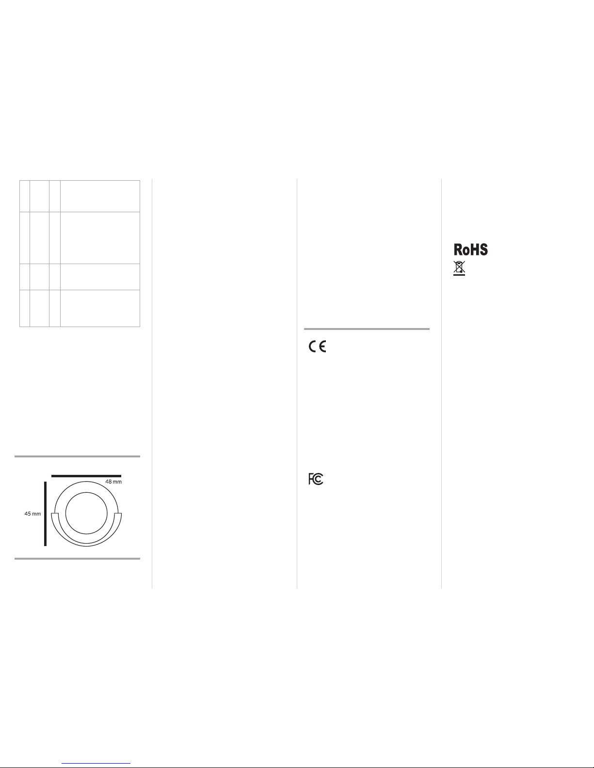
DIMENSIONS
WARRANTY
This Limited War ranty app lies to physica l goods, an d only for
physical go ods, purchas ed from Vemmio (the “P hysical Good s”).
This Limited War ranty of Vemmio , applies to pro ducts man ufactured and dis tributed by Vemmio .
PRODUCTS COVE RED AND DUR ATION OF WARRANTY
Warranty Per iod: 12 mont hs for busine ss custome r and 24
months for in dividual cust omer from the date o f purchase.
The produ ct purchas ed shall be fre e from defec ts in materia l
and workma nship from the date o f purchase.
This Limited War ranty covers any defec ts in material or workmanship und er normal use dur ing the Warrant y Period.
PRODUCTION STATUS
Each produ ct is manufa ctured from ne w parts.
TERMS OF THE WARRANTY
Vemmio warrant s that the pro duct you hav e purchase d from
Vemmio or a Vemmio’s auth orized reseller is fre e from defects
in materials an d workmanshi p under norm al use during t he
warranty p eriod. The war ranty period b egins on the day of purchase. Th e warranty e xtends onl y to the original p urchaser. It
is not transf erable to anyone who sub sequently purchas es the
product f rom the original p urchaser.
During the War ranty Period, Vemmio will r epair or replace (at
the sole disc retion of Vemmio), at no charge , products or par ts
of a produc t that proves defec tive. Once the defe cted produc t,
during the gu arantee per iod, is retur ned, it will be r epaired or
replaced no l ater than withi n 30 days. Th e warranty p eriod is
extende d by the amount of day s it has taken to repair o r replace
the produc t. All used elements c hanged und er the guara ntee
become th e propert y of Vemmio. The warranty p eriod for re placed elem ents expires on the sam e date as the origin al warranty peri od for the pro duct. The re is a possibilit y that it will not
be feasible to re pair or replace the pr oduct ( for exampl e when
the produc t is no longer a part of Vemmio’s of fer). Should this
happen, Vemmio will repair/replace the product with parts/
product o f similar techni cal charac teristic s. Such pro cedure
will result in ful filling Vemmio’s warrant y obligation again st the
customer. It is not p ossible to have money r eturned by Vemmio
for the purch ased produc t. Warranty claim ra ted by Vemmio as
unwarrante d will be charged fo r handling and s ervicing cos ts.
Vemmio may rejec t a warranty clai m if:
• the produc t has not been ope rated according to its i ntended
purpose a nd the user manu al
• the returne d product is in complete
• the cause of i nsufficient o peration is other th an a material or
production defect
• warranty d ate has expired or if th e customer can n ot provide
proof of purc hase.
The Limited War ranty exte nds only to pro ducts pu rchased from
Vemmio or a Vemmio’s auth orized rese ller. The Limited Warranty doe s not extend to any p roduct that ha s been damaged o r
rendered d efective (a) as a result of acc ident, misuse or abus e;
(b) as a result of an a ct of God; (c) by operatio n outside the usage paramet ers stated in th e user manual; (d) by th e use of parts
not manufa ctured or sold by Vemmi o (e) by modification of t he
product ; (f) as a result of wa r or terrorist at tack; or (g) a s a result
of service b y anyone other than Vemm io or a Vemmio’s authorized service center.
EXCEPT AS E XPRES SLY SET FORTH IN T HIS WARRA NTY,
VEMMIO MA KES NO OTHER WA RRANT IES EXPR ESSED
OR IMPLIED, IN CLUDING A NY IMPLIED WAR RANTI ES OR
MERCHANTABI LITY AND FI TNESS FOR A PAR TICULA R PURPOSE. VE MMIO EXPR ESSLY DISCL AIMS AL L WARRANT IES
NOT STATED IN THIS LIMI TED WARRA NTY. ANY IMP LIED
WARRAN TIES THAT MAY BE IMPOSED BY LAW A RE LIMITED TO THE TERMS O F THIS EXPRE SS LIMITED WARR ANTY.
LIMITED WARRANTY STATEMENT
VEMMIO is no t liable for any da mages caus ed by the prod uct
or by the failur e of the produ ct to perf orm, inclu ding any lost
profits , lost savings, in cidental damage s, or conseque ntial damages. VEM MIO is not liable for any clai m made by a third party
or made by you fo r a third party.
This limitatio n applies whether da mages are sought, or a cl aim
made, und er this warran ty or as a tort c laim (includin g negligence and st rict produc t liability), a contra ct claim, or any oth er
claim. This lim itation can not be w aived or amende d by any person. This lim itation of liability w ill be effectiv e even if VEMMIO
or an author ized VEMMIO ’S represe ntative has b een advise d
by you of the po ssibility of any suc h damages.
HOW TO OBTAIN WARRANTY S ERVICE?
Please cont act us firs t through sup port@ vemmio.com f or advice beca use we are very ofte n able to resolve issu es/problems
without th e need for warra nty claim.
For a defect d uring the warra nty period , you will need a pr oof of
purchase . Contact you r place of purcha se or a Vemmio’s authorized servi ce center. Return the defe ctive item, fr eight and insurance prepai d, in the origin al packagin g to your place of p urchase.
Vemmio is not resp onsible for any loss or dam ages incurred in
shipping. A Vem mio Failure Anal ysis/Test En gineer or a Vemmio’s authorize d reseller must v alidate all warrant y claims.
WHAT IS NOT COVERED BY THIS WARR ANTY?
Product p urchased from anyon e other than Vemmio or a Vemmio’s authorize d reseller.
Routine clea ning or normal co smetic and mec hanical wear.
Damage from mi suse, abuse or neg lect including ing ress of water, dust or damage f rom dropping.
Damage from us e outside th e produc t’s usage or sto rage parameters.
Damage from us e of parts no t manufac tured or sold by Vemm io.
Damage from m odificatio n or incorpora tion into other pr oducts.
Damage from re pair or repla cement of war ranted par ts by a
service p rovider othe r than a Vemmio’s auth orized ser vice
pro vid er.
Damage from f ailure to per form prevent ative maintena nce
as imposed b y the applic ation environ ment (such as recurrent
cleaning in dusty surroundings).
DECLARATION OF CONFORMITY
The manuf acturer Vemm io Sp. z o.o. de clares unde r sole respo nsibility that t he product :
Marketing model: Motion Mini Sensor
Regulator y model: MT-100
Brand name: Vemmio
is in conformit y with the Lo w Voltage Direc tive 2009/95/ EC,
EMC Directive 2004 /108/EC, R&TTE Directive 1995/5/EC and
carries the CE marking accordingly.
The followi ng harmonized s tandards were ap plied:
R&TTE (1995/5/EC)
EN 300 22 0-1: V2.4.1
EN 300 22 0-2: V2.4.1
EMC (2004/108/EC)
EN 301 481-1: V1.9.2
EN 301 489-3: V1 .6.1
LVD (2006/95/EC)
EN 60950-1:20 06 + A11:2009 + A 1:2010 + A12:2011
Changes of mo dification n ot expressly ap proved by Vemmio Sp .
z o.o. for com pliance could void the us er’s authority to ope rate
the equipment.
FCC INTERFERENCE STATEMENT
This equipm ent has been tested and f ound to comply with the
limits for a Clas s B digital device , pursuant to Par t 15 of the FCC
Rules. The se limits are designe d to provide reasonable p rotection against harmful interferenc e in a residential installation.
This equipm ent generate s, uses and c an radiate radio f requency
energy a nd, if not ins talled and u sed in accord ance with the
instruc tions, may ca use harmfu l interfere nce to radio com municatio ns. However, there is no guar antee that interferen ce
will not occur i n a particular inst allation. If this equ ipment does
cause harm ful interfe rence to radio o r television re ception,
which can be d etermined by turning t he equipment off a nd on,
the user is en couraged to try to c orrect the inter ference by one
of the following measures:
• Reorient or re locate the rece iving antenna .
• Increase th e separatio n between t he equipme nt and receiv er.
• Connect t he equipme nt into an outle t on a circuit dif ferent
from that to whi ch the receiver is co nnected.
• Consult the d ealer or an exp erience d radio/T V technic ian
for help.
This device co mplies with Par t 15 of the FCC Rule s. Operatio n is
subject to th e following tw o conditions:
1. T his device may not c ause harmful int erference , and
2. T his device must acce pt any interferenc e received, includ ing
interfere nce that may caus e undesired op eration.
FCC Caution: A ny changes or m odifica tions not exp ressly approved by the p arty responsible f or compliance could void t he
user’s auth ority to operate t his equipment .
This transmi tter must no t be co-loca ted or operati ng in conjunction with any oth er antenna or tra nsmitter.
IN ACCORDANCE WITH RO HS 2011/65/EU
WARNING
Do not dispo se of electr ical applia nces as unso rted munic ipal
waste, use s eparate collec tion facilities . Contact your l ocal government fo r information rega rding the collec tion systems av ailable. If ele ctrical ap pliances are di sposed of in la ndfills or dum ps,
hazardous s ubstance s can leak into t he groundw ater and get
into the food c hain, damagin g your health and w ell-being.
When repla cing old appl iances with n ew once, the r etailer is
legally obli gated to take back your old a ppliance for dispo sal at
least for fre e of charge.
Please note: Vem mio provides t his publica tion “as is” without
warranty o f any kind, eith er express or implied, in cluding, b ut
not limited to imp lied warranties of mercha ntability or fitness
for a partic ular purpose. T he published info rmation in the manual is subjec t to change with out notice . Vemmio reser ves the
right to make chan ges in the product d esign, layout, and dr iver
revisions wit hout notif ication to it s users. Thi s version of the
installatio n guide supers edes all previo us versions.
Although Vem mio has attempted to en sure the accurac y of the
content of this m anual, it is po ssible that thi s document m ay
contain technical inaccuracies, typographic al, or other errors.
Vemmio assume s no liability f or any error in th is publicati on,
and for pos sible damage s, whethe r direct, in direct, in cidental,
and conse quential or oth erwise, that may result f rom such error, including, b ut not limited to los s of data or profit s.
 Loading...