

Vemmio DS-100 Owner's Manual
WWW.VEMMIO.COM
double
switch
MODEL: DS-100
V1.0
INTRODUCTION
Thank you for c hoosing Vemmio. We welcome yo u in our customer society.
Vemmio Doubl e Switch is a dual relay in- wall module. T he product works a s a transceiver and is a Z-Wave Plus en abled device.
Mini size design l ets the module be easily h idden into the w all
box to do not inter fere with ho use decorat ion. One of ma ny uses
of the Doubl e Switch is to turn on or off th e connected fit tings
and monitor p ower consump tion in real time. T he new smart re lay calibratio n technology can wo rk perfectly wit h many kinds
of lights like: incandescent, fluorescent and LED lights.
PACKAGE CONTENTS:
• user manual
• Double Swi tch.
KE Y FE ATU RE S
Remotely cont rol your equip ment and fitti ngs ( On/Of f )
Two channels use d separately ( 2 x 1500 W )
Monitor pow er consumpti on in real time
If an overload (>1600 -1700 W) is detecte d, the modul e automatically cu ts off the po wered circuit
Mini size desig n lets the module be ea sily hidden into the wall
box
SPECIFICATION
Wireless standard Z-Wa ve Plu s
Frequency 868.4 0 MHz
Network range 40 m indoo r/ 100 m line
of sight
Operating temperature 0°C ~ 40 °C
Maximum Load 6.5 A (230 VAC/120 VAC)
(Resistive load)
Operating Voltage 100 to 240 VAC
Control circuits Two channels 2 x 150 0 W
INSTALLATION
DANGER
RISK OF ELEC TROCUTION
All work on the d evice shoul d only be carr ied out by trai ned
and skilled electricians. Observe the country-specific regulations.
DANGER
RISK OF FATAL INJURY FROM ELEC TRIC CURRENT.
The device ha s no basic insu lation and mu st therefore be installed in a way t hat protects a gainst accid ental contac t.
DANGER
RISK OF FATAL INJURY FROM ELEC TRIC CURRENT.
When insta lling a wall plate, t he distance be tween the cover ’s
fixing brac kets or screw s and the con nections o f the flushmounted Do uble Switch must be a t least 4 mm once inst alled.
If the dista nce is less than 4 m m, a deeper in stallation b ox must
be used. Th e fixing brackets or scre ws of the cover must not
press agai nst the hous ing. Only ins ulated tools ma y be used for
operation o n the device, e. g. an insulated p hase tester.
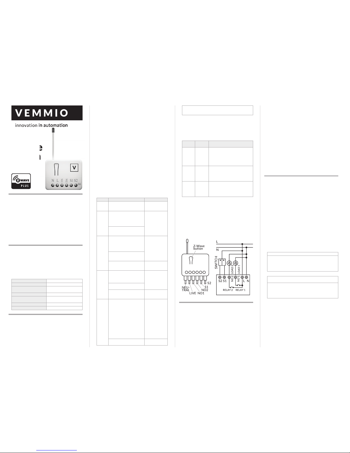
ADDING TO Z-WAVE NETWORK
The Z-Wave button, lo cated in the front c asing, can tog gle Double Switch on an d off, add, rem ove, reset or ass ociate the sens or
to Z-Wave network.
FIRST INCLUSION
Follow the ins tructions for your Z-Wave certi fied controller to
enter the desi red mode an d then follow t he instruc tions from
the table be low. When power is app lied for the first time , LED
flashes on an d off at 0. 5 second int ervals. It i mplies that th e
Double Swi tch has not been assig ned a node ID and st arts auto
inclusion . Auto inclusion wil l be executed.
Please note: f irst inclusion may va ry depending on yo ur gateway - please se e gateway manual fo r details.
Please note: Au to inclusion timeout i s 2 minute during which
the node inf ormation of ex plorer fram e will be emitted once
every severa l seconds . Unlike “inclu sion” func tion as show n
in the table b elow, the execution of a uto inclusion is fre e from
pressing th e Z-Wave button.
Function Description Annotation
No node IDThe Z-Wave Controller do es
not allocat e a node ID to the
Switch.
LED 2-second on,
2-second off
Inclusion*1. Put your Z-Wave control -
ler into inclus ion mode by
following the instructions
provided by t he controller
manufacturer.
One press o ne
flash LED
2. Pressing Z-Wave but ton
three times within 2 seconds
will enter incl usion mode.
Exclusion
1. Put your Z-Wave control -
ler into exclusi on mode by
following the instructions
provided by t he controller
manufacturer.
One press o ne
flash LED
1. Pressing Z-Wave but ton
three times within 2 seconds
will enter exclu sion mode.
3. Node ID h as been exclude d. LED 0.5s On , 0.5s
Off (Enter a uto
inclusion)
Facto ry
Reset
1. Pressing Z-Wave but ton
three times within 2 seconds
will enter incl usion mode.
Use this proc edure
only in the even t
that the prima ry
controller is l ost or
otherwise inoperable.
2. Within 1 se cond, press O n/
Off button again for 5 seconds.
3. IDs are excl uded. LED 0.5s On, 0 .5s
Off (Enter a uto
inclusion)
Association
1. The Dou ble Switch is an
always listen ing Z-Wave device, so ass ociations can
be added or r emoved by a
controller at a ny time.
Or If your controller requires
to have the Doub le Switch
send a ‘node in formation
frame’ or NIF f or association s,
pressing th e Z-Wave button
three times within 2 seconds
will cause th e Double Switch
to send
LED one pres s one
flash
2. There ar e 3 groups for the
switch
Including a n ode ID allocate d by Z-Wave Controller means
inclusion . Excluding a no de ID allocated by Z-Wave Contr oller
means exclusion.
If the first a ttempt of exclusio n is unsuccessf ul, please repeat
the proces s following all s teps carefull y.
*Please note : Always exclude a Z-wave produc t before trying
to add it to a Z-Wave network .
ASSOCIATION
Group ID Maximum
Nodes
Description
1 1 For group 1, th e Switch will repo rt (1)
ON/OFF st atus of Relay1 and Relay 2
(2) Instant Power Consumption
(Watt) of Relay 1 and Relay2 (3) Accumulated Power C onsumption (K Wh)
of Relay1 and Relay 2 to Group1 node.
2 1 For group 2, t he Switch will repo rt (1)
ON/OFF st atus of Relay1 (2) Inst ant
Power Consu mption (Watt) of R elay1
(3) Accumulated Power Consumption
(KWh) of Relay1 t o Group2 node.
3 1 For group 3, t he Switch will repo rt (1)
ON/OFF st atus of Relay2 (2) Ins tant
Power Consu mption (Watt) of R elay2
(3) Accumulated Power Consumption
(KWh) of Relay 2 to Group3 nod e.
PHYSICAL INSTALLATION
Choosing a Suitable Location
1. D o not locate th e Double Switch f acing direct s unlight, humi d
or dusty pl ace.
2. T he suitable a mbient temp erature for th e Double Sw itch is
0°C~40°C.
3. D o not locate the D ouble Switch near c ombustible sub stanc-
es or any sourc e of heat, e.g . fires, radiato rs, boiler etc .
4. A fter putting it into use , the body of D ouble Switch will be-
come a little b it hot.
Assembly drawings
MOUNTING
1. P ut the Doubl e Switch into a wall b ox and conne ct the wires L ,
N to the Doubl e Switch connec tor L, N.
2. C onnect th e wall switch to t he Double Sw itch accordin g to
the above assembly drawings.
3. To manu ally turn on the Do uble Switch, pre ss and release th e
Z-Wave button. The LED w ill flash for 1 second , and the load
plugged in to the Double Swi tch will become a ctive.
4. To manu ally turn off the Do uble Switch, simply p ress and re-
lease the Z-Wave button . The LED will flash fo r 1 second and
the load plu gged into the D ouble Switch wil l become inac tive.
FIRMWARE UPDATE OVER THE AIR (OTA)
Double Swi tch support s Firmware Upda te Command
Class, it can r eceive the up dated firmwa re image sent by c ontroller via the Z-wave RF m edia.
Supported Command Classes
COMMAND_CLASS_ZWAVEPLUS_INFO
COMMAND_CLASS_VERSION_V2
COMMAND_CLASS_MANUFACTURER_SPECIFIC_V2
COMMAND_CLASS_DEVICE_RESET_LOCALLY
COMMAND_CLASS_ASSOCIATION_V2
COMMAND_CLASS_ASSOCIATION_GRP_INFO
COMMAND_CLASS_POWERLEVEL
COMMAND_CLASS_SWITCH_BINARY
COMMAND_CLASS_BASIC
COMMAND_CLASS_SWITCH_ALL
COMMAND_CLASS_ALARM
COMMAND_CLASS_SCENE_ACTIVATION
COMMAND_CLASS_SCENE_ACTUATOR_CONF
COMMAND_CLASS_PROTECTION
COMMAND_CLASS_FIRMWARE_UPDATE_MD_V2
COMMAND_CLASS_MULTI_CHANNEL_V3
COMMAND_CLASS_METER_V3
COMMAND_CLASS_CONFIGURATION
PROGRAMMING
BASIC COMMA ND CLASS / BI NARY SWITCH COMMA ND
CLASS
The Switch wil l respond to BA SIC and BINARY SWITC H commands that ar e part of the Z Wave sys tem.
1-1 BASIC_GET / BI NARY_SWITCH_G ET
Since the sw itch has two re lays, the Switc h will report its On/
Off stat e to the Controlle r by setting Conf iguration pa rameter 3.
Configuration parameter 3=1
Report ON w hen relay 1 ON
Report OF F when relay 1 OFF
Configuration parameter 3=2
Report ON w hen relay 2 ON
Report OF F when relay 2 OFF
Configura tion parameter 3 =3 (default)
Report ON w hen either relay 1 O N or relay 2 ON
Report OF F when both relay 1 an d relay 2 OFF
Basic Get Com mand: [Comman d Class Basic, Ba sic Get]
Basic Repor t Command:
Report O FF: [Command Clas s Basic, Basic Re port, Value =
0(0x00)]
Report ON : [Command Clas s Basic, Basic Re port, Value =
255(0 xFF)]
Binary Swi tch Get Comman d: [Command Class S witch Binary, Switch Bin ary Get]
Binary Swi tch Report Com mand:
Report OF F: [Command Class S witch Binary, Switc h Binary
Report, Value = 0(0x00)]
Report ON : [Command Clas s Switch Binary, Swit ch Binary
Report, Valu e = 255(0xFF)]
1-2 BASIC_S ET / SWITCH_ BINARY_SET
Since the sw itch has two relays, the lo ad attached to the Do uble Switch will t urn on or off up on receipt of t he followin g
commands f rom a Z-Wave Co ntroller by setting Conf iguration
parameter 3.
Configuration parameter 3=1
switch ON an d OFF of relay 1
Configuration parameter 3=2
switch ON an d OFF of relay 2
Configuration parameter 3=3(default)

WWW.VEMMIO.COM
switch ON an d OFF both relay 1 an d relay 2
[Command Cla ss Basic, Basi c Set, Value = 1~99, 255(0xFF)]:
the load at tached to the Sw itch turns on.
[Command Cla ss Basic, Basi c Set, Value = 0(0x 00)]: the load
attache d to the Switch turns o ff.
[Command Cla ss Switch Binar y, Switch Binary Se t, Value =
1~99, 255(0xFF)]: the loa d attached to th e Switch turns on .
[Command Cla ss Switch Binar y, Switch Binary Se t, Value =
0(0x00)]: the loa d attached to th e Switch turns of f.
2. Z-Wave’s Groups (As sociation Comm and Class Version 2)
The Switch ca n be set to send r eports t o control asso ciated Z-Wave devices. It sup ports 3 a ssociation g roups which
every grou p has one nod e support . Group1~Grou p3 suppor t
SWITCH_BINARY_REPORT,
METER_REPORT_COMMAND_V3
For group 1, th e Double Switch will repo rt (1) ON/OFF st atus
of Relay1 and Relay 2 (2) Instant Power Con sumption (Watt) of
Relay1 and Relay2 (3 ) Accumulated Pow er Consumptio n (KWh)
of Relay1 and Relay 2 to Z-Wave Controller.
For group 2, t he Double Sw itch will report (1) ON/OFF st atus
of Relay1 (2) Inst ant Power Con sumption ( Watt) of Relay1 (3)
Accumulate d Power Consumption (K Wh) of Relay1 to Z-Wave
Controller.
For group 3, t he Double Sw itch will report (1) ON/OFF st atus
of Relay2 (2) Ins tant Power Con sumption (Watt) of Relay2 (3 )
Accumulate d Power Consumption (K Wh) of Relay2 to Z-Wave
Controller.
2-1 Auto report to Gro uping 1 ~3 (Maximum N ode 1)
2-1-1 O n/Off Event Repo rt
When “on” or “off” s tate has been changed, i t will send Bina ry
Switch Repor t to the nodes o f Group1~3.
Binary Swi tch Report
ON:[Command Cla ss Switch Bina ry, Switch Binar y Report ,
Value =255 (0xFF)]
OFF:[Comma nd Class Switc h Binary, Switch B inary Rep ort,
Value =0 (0x 00)]
2-1-2 Instant Power Consum ption vary over 5% re port
When the po wer consumption o f load vary over 5% , it will send
Meter repo rt to the nodes o f Group
Meter Repor t Command:
[Command Cla ss Meter, Meter Report , Rate Type = 0x01, Meter Type = 0x01,
Precision = 1 , Scale = 0x02 , Size = 4, Meter Value (W) ]
2-1-3 overload alarm report command
When DOU BLE SWITCH d etects th e overload, i t will send
Alarm Repor t to the corresp ond Group.
The content of A larm Report
Alarm report command: [Command_Class_Ala rm, Alarm_Re-
port, Ala rm Type = 0x08,
Alarm Level = 0x FF]
2-2 Response to Mete r Get Command
The Doubl e Switch will rep ort its (1) instant Power Con sumption (Watt) o r (2) accumula ted power con sumption( KWH) or
(3) AC load Voltage ( V) or (4) AC load cur rent ( I ) (5) load power
factor (PF ) to Z-Wave Controller aft er receive the M eter Get
Command fr om Z-Wave Controller.
2-2-1 Instant Power Consum ption (Watt) of Sw itch
When recei ving Meter Get Comman d, it will report Meter Re port Com mand to the node a sked.
Meter Get Co mmand: [Com mand Class Me ter, Meter Get,
Scale =0x02(W)]
Meter Repor t Command:
[Command Cla ss Meter, Meter Report , Rate Type = 0x01, Meter Type = 0x01,
Precision = 1 , Scale = 0x02 , Size = 4, Meter Value (W) ]
2-2-2 Accumulated Power Co nsumption (K W/h)
When recei ving Meter Get Comman d, it will report Meter Re port Com mand to the node a sked.
Meter Get Co mmand:
[Command Cla ss Meter, Meter Get, S cale = 0x00 K W/h)]
Meter Repor t Command:
[Command Cla ss Meter, Meter Repor t, Rate Type = 0x01, Me ter Type =0x01 , Precision = 2 , Scale = 0x 00, Size = 4, M eter
Value (KWh)]
Accumulate d power consu mption (K W/h) = (Meter Value
2*65536) + (Meter Value 3 *256) + (Meter Val ue 4) = 800 .35
(KW/h )
2-2-3 Clearing accum ulated power con sumption
Whenever re-start counting the accumulated power consumption is need ed, you can use M eter Reset Comma nd to clear it.
Meter Reset C ommand: [Command Class Meter, Meter Reset]
2-2-4 AC load Voltage (V )
When recei ving Meter Get Comman d, it will report Meter Re port Com mand to the node a sked.
Meter Get Co mmand: [Comm and Class Me ter, Meter Get,
Scale =0x04(V)]
Meter Repor t Command:
[Command Cla ss Meter, Meter Report , Rate Type = 0x01, Meter Type = 0x01, Pre cision = 1, Sc ale = 0x04, Size = 2, Mete r
Value(V)]
2-2-5 AC load current ( I )
When recei ving Meter Get Comman d, it will report Meter Re port Com mand to the node a sked.
Meter Get Co mmand: [Comm and Class Me ter, Meter Get,
Scale =0 x05(I)]
Meter Repor t Command:
[Command Cla ss Meter, Meter Report , Rate Type = 0x01, Meter Type = 0x01,
Precision = 2 , Scale = 0x05 , Size = 2, Meter Value (I)]
2-2-6 load power fa ctor (PF)
When recei ving Meter Get Comman d, it will report Meter Re port Com mand to the node a sked.
Meter Get Co mmand: [Comm and Class Me ter, Meter Get,
Scale =0x06 (PF)]
Meter Repor t Command:
[Command Cla ss Meter, Meter Rep ort, Rate Type = 0x 01,
Meter Type = 0x01 , Precision = 2, Sc ale = 0x06, Size = 1 By tes,
Meter Value(PF)]
2-3 Multi Channe l Command Class Ver sion 3
DOUBLE S WITCH also suppo rts Multi Chann el command class
(version 3), whi ch include
BINARY_SWITCH_GET, BINARY_SWITCH_SET, BASIC_GET,
BAS IC_ SE T,
METER_SUPPORTED_GET, METER_RESET, METER_GET
You may control or get r eport fro m 3 endpoint s of DOUBL E
SWITCH.
2-3-1 BINARY_SWITCH _GET,
You may get the ON/O FF state from ev ery endp oint, when
endpoint s et to 1, DOUBLE SWI TCH will reply state of Relay1 .
If endpoint s et to 2, DOUB LE SWITCH will re ply state of Relay 2.
If endpoint s et to 3, DOU BLE SWITCH w ill reply ON (0 xFF)
when eithe r Relay 1 or Relay2 is ON, repor t OFF (0x00) wh en
both Relay 1 and Re lay2 are OFF. Below is a n example sh owing a source en dpoint 5 sen ding a Get comm and to DOUB LE
SWITCH endp oint 3.
Please note: t he below tab les prese nt informati on for the foll owing:
COMMAND_CLASS_MULTI_CHANNEL
MULTI_CHANNEL_CMD_ENCAP
Source End Po int = 0x05 (this is the endp oint of
command inquirer here we
assume end point is 5, if the
inquirer doesn’t suport multi
Channel this v alue will be 0)
(Bit Address+Destination End
Point = 0x03 )
(Bit Address =0; Destinati on
End Point rang e from 1~3)
Command Cla ss = 0x25 (Command_Class_Switch_Bi-
nary = 0x 25)
Command =0x02 (Switch_ Binary_Get = 0 x02)
Below is the ex ample show D OUBLE SW ITCH repor t to last
command
Source End Po int = 0x03 Since the en dpoint is 3 so
DOUBLE S WITCH will reply
ON(0xFF ) when either R elay
1 or Relay2 is ON , report OFF
(0x0 0) when both Relay 1 a nd
Relay2 are OFF
(Bit Address+Destination End
Point = 0x05 )
(Bit Address = 0; Destination
End Point
Command Cla ss = 0x25 (Command_Class_Switch_
Binary=0x25)
Parameter 1 = 0 xFF (ON=0xFF, OFF=0x00 )
2-3-2 BINARY_SWITCH _SET
By using BINA RY_SWITCH _SE T Command o f Multi Channe l
Command Cla ss Encapsul ation Comman d, you can s witch Relay1 ON/OFF by s etting end point to 1, or s witch Relay2 ON /
OFF by settin g endpoint to 2, or s witch both Relay1 and R elay2
ON/OFF by set ting endpoin t to 3
The exampl e of the comman d shows that s witch off re lay1 of
DOUBLE SWITCH
Source End Po int = 0x01 (this is the endp oit of com-
mand inquirer here
we assume edn point is 1, if the
inquirer doesn’t
suport mu lti channel, th is
value will be 0)
(Bit Address+Destination End
Point=0x01)
(Bit Address = 0; Destination
End Point rang e 1-3
Command Cla ss = 0x25 (Command_Class_Switch_
Binary=0x25)
Command =0x01 (Switch_ Binary_S et = 0x01)
Parameter 1 = 0 x00 (ON=0xF F , OFF=0x0 0)
2-3-3 METER_SUPPORTED_GET
This comman d is to ask the endpo int of DOUBLE S WITCH what
kind of meter da ta can be repor ted.
The exampl e shows how to get th e meter repor t type
Source End Po int = 0x01 (this is the endp oint of
command inquirer here we
assume end point is 1, if the
inquirer doesn’t support Multi
Channel this v alue will be 0)
(Bit Address+Destination End
Point = 0x03 )
(Bit Address =0; Destinati on
End Point range1~3)
Command Cla ss = 0x32 (Command_Cla ss_Meter_V3
= 0x32)
Command =0x03 (Meter_Supp orted_Get =
0x03)
Below is the ex ample show D OUBLE SW ITCH repor t to last
command
Source End Po int = 0x03
(Bit Address+Destination End Point = 0x01)
Command Cla ss = 0x32
Command Cla ss = 0x32
(Command_Cla ss_Meter_V3
= 0x32)
Command =0x04 (Meter_Supp orted_Repo rt
= 0x04)
Parameter 1 = 0 x81 (Meter Reset =1, Me ter
Typ e=0 x0 1)
Parameter 2 = 0 x75 (Scale Supp orted =
KWh +W+V+A+Powe r Facto r
= 0x75)
2-3-4 METER_RESET
This comman d is to reset the Acc umulated Power Co nsumption
(KWh) to 0
The exampl e shows how to rese t the KWh
Source End Po int = 0x03 (this is the endp oint of com-
mand
inquirer, here we assume
endpoint is 3, if the inquirer
doesn’t sup port multi
Channel this v alue will be 0)
(Bit Address+Destination End
Point = 0x01)
(Bit Address = 0; Destination
End Point = rang e 1-3
Command Cla ss = 0x32 (Command_Cla ss_Meter_V3
= 0x32)
Command =0x05 (Meter Reset = 0 x05)
2-3-5 METER _GET:
Using meter get c ommand to get the K WH, W, V, I, PF from en dpoint of DOU BLE SWITCH 2-3-5 -1 Get KWH from endp oint
Meter_GET example:
Source End Po int = 0x05 (this is the endp oint of
command inquirer, here we
assume end point is 5, if the
inquirer doesn’t support multi
Channel this v alue will be 0)
(Bit Address+Destination End
Point = 0x03 )
(Bit Address =0 ; Destination
End Point range1~3)
Command Cla ss = 0x32 (Command_Cla ss_Meter_V3
= 0x32)
Command =0x01 (Meter_Get = 0x 01)
Parameter 1 = 0 x00 (Scale = KW H = 0X00)
Accumulated power consumption (KWH) Report example:
Source End Po int = 0x03 (Meter repo rt = Endpoint3)
(Bit Address+Destination End
Point = 0x05 )
(Bit Address =0; Destinati on
End Point = comm and in-
quirer’s Endpoint value)
Command Cla ss = 0x32 (Command_Cla ss_Meter_V3
= 0x32)
Command =0x02 (Meter_Report = 0x02)
Parameter 1 = 0 x21 (Scale Bit2 = 0 , Rate Type =
0x01, Meter Type=0x01)
Parameter 2 = 0 x44 (Precision = 2, S cale Bit1Bit0
= 0, Size = 4)
Accumulated Power Con-
sumption =0x000005FD =
15.33 KWh
Parameter 3 = 0 x00
Parameter 4 = 0 x00
Parameter 5 = 0 x05
Parameter 6 = 0 xFD
2-3-5-2 Get Insta nt Power Consum ption (Watt) fro m endpoint
METER_GET example:
Source End Po int = 0x05 (this is the endp oint of
command inquirer, here we
assume end point is 5, if the
inquirer doesn’t support multi
Channel this v alue will be 0)
(Bit Address+Destination End
Point =0x03)
(Bit Address =0:Des tination
End Point rang e 1~3)
Command Cla ss = 0x32 ( Command_Class_Meter_V3
= 0x32)
Command = 0 x01 (Meter_Get = 0x01)
Parameter 1 = 0 x10 (Scale = W = 0x0 2)
DOUBLE S WITCH Insta nt Power Cons umption ( W) Repor t
example:
Source End Po int = 0x03 (Meter repo rt = Endpoint 3)
(Bit Address+Destination End
Point = 0x05 )
(Bit Address =0 ; Destination
End Point = comm and in-
quirer’s Endpoint value)
 Loading...