


- 29 -
User Manual Digital Heat Regulators
English
Contents
� Safety warnings Page 30
� Technical specifications Page 30
� Description of instrument Page 33
� Electrical connections Page 33
� Glossary Page 34
� Operation Page 39
� Setting the regulation parameters Page 39
� Parameter menu Page 41
� Error messages Page 48
� Reference standards Page 49
� Dimensions and connection diagrams, 33x75 mm Page 50-52
� Dimensions and connection diagrams, 72x72 mm Page 53-54
� Dimensions and connection diagrams, 4-DIN Page 55-56
English

- 30 -
User Manual Digital Heat Regulators
English
� During the installation and operation of the instrument, follow the
instructions set out below:
1) The instrument should be installed by a skilled operator.
2) Strictly follow the connection diagrams when installing the instrument.
3) Do not power or connect the instrument if any part of it is damaged.
4) Before touching the terminals, make sure the wires to be connected to
the instrument are not live.
5) The connection cables should be able to resist the maximum operating
temperature (Tmax), obtained from the sum of the maximum ambient
temperature (Ta) + a temperature of 20 °C (Tmax= Ta + 20 °C).
6) The instruments guarantee a main insulation between the low voltage
(250 V) and very low voltage parts.
7) Any outside switches connected to the controls should guarantee a
minimum insulation at operating temperature of 250 V AC, or should be
protected by equivalent insulation.
8) Contacts: all type 1C (CEI 107-70 and variants).
9) The instruments require no maintenance.
� Series of digital temperature regulators satisfying the simplest requirements in
the field of heat regulation. They can be used as heating or refrigeration regulators
and as maximum/minimum alarms.
� Three dedicated base models for probe input:
- PTC thermal resistances (Pos. Temp. Coeff.) - Ni100, Pt100 HT NiPt
- NTC thermal resistances (Negative Temperature Coefficient) HT NTC
- TC thermocouples - J, K, L, R, S, T, E, N HT JK
• F
or each single model, the probe input can be configured from the keyboard.
• T
wo probe inputs for the HT NTC models, for the measurement of two temperatures
that can be displayed alternatively by the closure or opening of an outer consensus
to be connected to the instrument, or directly from the keyboard for the 72x72 mm
rear panel version (this version has no digital input).
• Available in versions with 1 or 2 relay outputs with exchange contact.
• Heat regulators with 3 digit, seven segment and decimal point display.
• Relay intervention signalling lamp.
• T
emperature T2 signalling lamp (only models HT NTC-..P7.. and HT NTC-..D..)
• Display range: -99 ÷ +999 °C
• Display resolution: 0.1 °C (-9,9 ÷ +99.9 °C) and 1 °C (< -9.9 °C and > +99.9 °C)
• Precision: ±0.5 % of the end of scale value ±1 digit
(at an ambient temperature of 23 °C)
• Sampling time: 0.5s
TECHNICAL SPECIFICATIONS
SAFETY WARNINGS
English

- 31 -
User Manual Digital Heat Regulators
English
• Digital parameter setting:
- Set point
- Differential
- Neutral zone
- Output drive times
- Digital input function and delay time
- Alarm delay / buzzer enable time
- Probe calibration offset
- Resolution displayed
- Temperature measurement unit
- Measurement display filter (update speed)
- Probe input type
- Password
- Operating modes (regulation):
— ON/OFF direct and/or reverse action with or without neutral zone
— PWM direct and reverse action and neutral zone
— ALARM
— Refrigeration mode
— Special mode
• 2
independent set points
• Digital input: 1 (not versions HT NiPt-..P7A, HT NTC-P7A, HT JK-..P7A) for outside
consensus for configurable function: outside alarm, regulation ON/OFF, selection
of probe to be displayed, set point switching, direct/reverse switching, etc
• Acoustic and visual alarm signals for: outside alarm (from digital input),
probe alarm (malfunction), minimum or maximum alarm
• Infrared receiver with RC-5 protocol (not versions HT NTC-1DA, HT NTC-2DA) for
remote control (accessory available separately for remote programming)
• Available in the following fixing versions: rear panel 33x75 mm,
rear panel 72x72 mm and modular 4 DIN
• P
ower supply: see table on the following page
• Rated power output: 3 VA for the rear panel 33x75 mm versions
4.5 VA for the rear panel 72x72 mm and modular 4 DIN versions
• Max absorption: 100 mA at 12 V 50 mA at 24 V (1 channel)
• Operating temperature: 0 ÷ +50 °C
• Operating humidity: <80%
• Storage temperature: -10 ÷ +70 °C (<80% RH)
• Protection level: front panel IP54 (IP40 for the 4 DIN module version)
terminals IP20
English

- 32 -
User Manual Digital Heat Regulators
English
Rear panel 33x75 mm
Code Model Power supply (*) Power supply n° of Digital Infrared
tollerance relays input receiver
VM627700 HT NiPt-1P3D from 12 to 24 V AC/DC ±10 1 YES YES
VM628500 HT NiPt-1P3A from 100 to 230 V AC
from 140 to 300 V DC
±15
1 YES YES
VM629300 HT NiPt-2P3D from 12 to 24 V AC/DC ±10 2 YES YES
VM634300 HT NTC-1P3D from 12 to 24 V AC/DC ±10 1 YES YES
VM635000 HT NTC-1P3A from 100 to 230 V AC
from 140 to 300 V DC
±15
1 YES YES
VM636800 HT NTC-2P3D from 12 to 24 V AC/DC ±10 2 YES YES
VM641800 HT JK-1P3D from 12 to 24 V AC/DC ±10 1 YES YES
VM642600 HT
JK-1P3A from 100 to 230 V AC
from 140 to 300 V DC
±15
1 YES YES
VM643400 HT JK-2P3D from 12 to 24 V AC/DC ±10 2 YES YES
Rear panel 72x72 mm
Code Model Power supply (*) Power supply n° of Digital Infrared
tollerance relays input receiver
VM625100 HT NiPt-1P7A 24/230 V AC ±10 1 NO YES
VM626900 HT NiPt-2P7A 24/230 V AC ±10 2 NO YES
VM632700 HT NTC-1P7A 24/230 V AC ±10 1 NO YES
VM633500 HT NTC-2P7A 24/230 V AC ±10 2 NO YES
VM639200 HT JK-1P7A 24/230 V AC ±10 1 NO YES
VM640000 HT JK-2P7A 24/230 V AC ±10 2 NO YES
Modular 4 DIN
Code Model Power supply (*) Power supply n° of Digital Infrared
tollerance relays input receiver
VM630100 HT NiPt-1DA 24/230 V AC ±10 1 YES YES
VM631900 HT NiPt-2DA 24/230 V AC ±10 2 YES YES
VM637600 HT NTC-1DA 24/230 V AC ±10 1 YES NO
VM638400 HT NTC-2DA 24/230 V AC ±10 2 YES NO
VM644200 HT JK-1DA 24/230 V AC ±10 1 YES YES
VM645900 HT JK-2DA 24/230 V AC ±10 2 YES YES
(*)
AC power supply - frequency 50/60 Hz
English

- 33 -
User Manual Digital Heat Regulators
English
Display
• A 3 digit led display with decimal point is used.
For all the models, the display range is:
- minimum display: -99 °C or -9.9 °C
- maximum display: 999 °C or 99.9 °C
Relay intervention signalling lamp:
• Out 1:
LED off if relay one is OFF, on if relay one is ON, flashing if relay one in OFF
is waiting to become ON due to an active timing.
• Out 2:
LED off if relay two is OFF, on if relay two is ON, flashing if relay two in OFF
is waiting to become ON due to an active timing.
Keys
• Three parameter setting keys are used:
Confirm and parameter programming/display key.
Key used to increase the parameter or go to the next parameter.
Key used to decrease the parameter or leave the menu.
• Adhere strictly to the instructions in the safety warnings and the
“connection diagram” section.
ELECTRICAL CONNECTIONS
OK
DESCRIPTION OF INSTRUMENT
English

- 34 -
User Manual Digital Heat Regulators
English
Set point (set or operating point)
• The set point is the value at which the appliance has to intervene to maintain the
measurement controlled at the required level.
Differential (or hysteresis)
• The differential is the maximum permitted variation from the set point for
the measurement controlled prior to the intervention of the appliance.
• This is usually set in such a way as to prevent rapid oscillations in the
measurement around the set point from causing frequent start-ups and
shutdowns of the appliance or the driver connected to it.
Direct action
• A regulator acts in direct mode when it
limits the measurement as this increases.
A typical example is a refrigerator: the
increase in temperature corresponds to
an increase in the refrigeration power
produced, with a view to reducing the
temperature
Reverse action
• A regulator acts in reverse mode
when it limits the reduction of the
measurement controlled.
For example, in a heating system, the
reduction in temperature
corresponds to an increase in heat
production
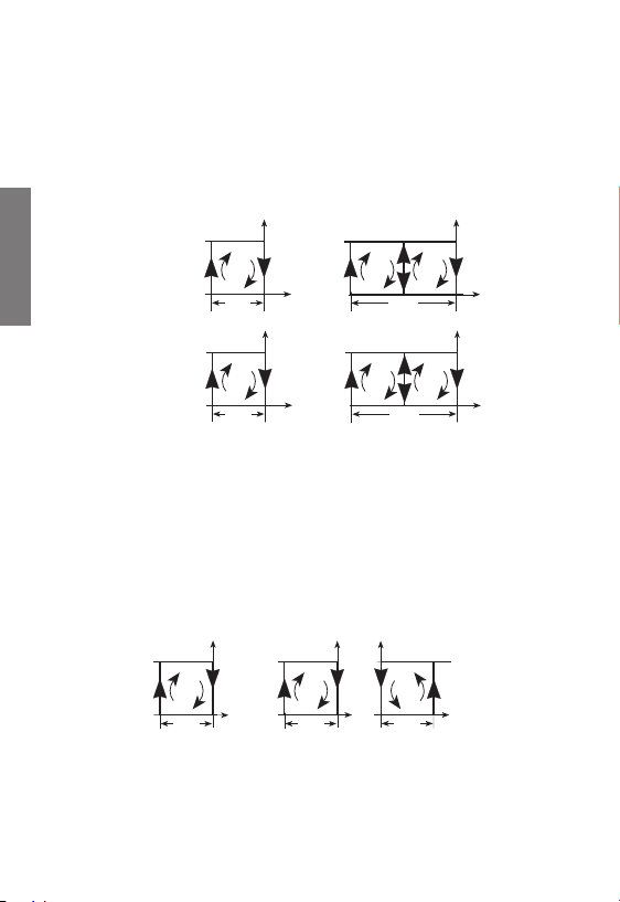
Neutral or dead zone (“dead-band”)
• This indicates an interval of values around the set point in which the measurement
regulated may oscillate without the activation of any output. It is normally used in
the appliances in which there is a strong inertia of the system, as a result of which
the set point may be exceeded even after the driver has been switched off or to
prevent the overlap of a heating and cooling action.
Around the neutral zone, no
output is activated. Outside the
neutral zone, the instrument
operates in direct mode if the
measurement controlled
increases, and in reverse if it
decreases.
GLOSSARY
Set
D
ON
OFF
Set + Diff
Temperature
Direct Mod
e
Set � Diff
R
ON
OFF
Set
Temperature
Reverse Mode
Set - Diff (R) - ZN
R
ON
OFF
Set
Temperature
D
Set + Diff (D) + ZN
Neutral Zone Mod
e
ZN
ZN
English

- 35 -
User Manual Digital Heat Regulators
English
PWM operation (in proportion to time)
• This is a neutral zone type of operation in which the relays are activated
periodically in impulse mode
(the interval can be set, see the
output menu).
The PWM procedure modulates
the power in accordance with the
position occupied by the
measurement within the
differential (the further we move
away from the set point, the more
the power increases).
Important: we advise against using this method to drive compressors,
due to the very close distance between start-up and shutdown.
Direct operating mode [PRO=0]
• In this mode, all the outputs
operate in direct. The values
of set point 1 [ST1] and
differential 1 [DF1] have
to be set. Hysteresis is to the
right of the set point. If both
outputs are used, the
hysteresis for each output is
equivalent to half the
differential. In this case,
output 1 will be activated when the measurement controlled reaches the value
[ST1]+[DF1]/2, at which point output 2 will be deactivated.
Reverse operating mode [PRO=1]
• In this mode, all the outputs operate in reverse.
The set point 1 [ST1] and differential 1 [DF1] values have to be set.
Hysteresis is to the left of the
set point. If both outputs are
used, the hysteresis for each
output is equivalent to half the
differential. In this case,
output 1 will be activated
when the measurement
controlled reaches the value
[ST1]-[DF1]/2, at which point
output 2 will be deactivated.
Set - Diff (R) - ZN
R
ON
OFF
Set
Temperature
D
Set + Diff (D) + ZN
PWM Mod
e
ZN
ZN
Set 1
D
ON
OF
F
Diff. 1
PRO=0 mode
OUT 1
Set 1
D
ON
OF
F
Diff. 1
OUT 1
D
OUT 2
1 output 2 outputs
Set 1
R
ON
OF
F
Diff. 1
OUT 2
R
OUT 1
2 output
s
Set 1
R
ON
OF
F
Diff. 1
OUT
1
1 output
PRO=1 mode
English

- 36 -
User Manual Digital Heat Regulators
English
Neutral zone operating mode [PRO=2]
• In this mode, output 1 operates in reverse and output 2 in direct.
The set point 1 [ST1], differential 1 [DF1] and neutral zone [DBN] values have
to be set. These are parameters for both outputs.
The regulator will tend to maintain the measurement controlled within the neutral
zone. Outside of this, output 2 will be activated if the measurement tends to
increase, or output 1 if it tends to decrease.
If a single output is present, this will operate in reverse, with the hysteresis shifted
towards the left of the value [DBN].
PWM operating mode [PRO=5]
• The regulation logic in this mode is the same as that with the neutral zone.
It is therefore necessary to set the set point 1 [ST1], differential 1 [DF1] and
neutral zone [DBN] values, which are parameters for both outputs.
In this operating mode, the relays are activated impulsively, with an interval that
can be set on the basis of the [TCL] value (see the output menu).
Within this interval, the relay will stay on for a period in proportion to the distance
of the measurement regulated from the set point (plus the neutral zone, where
applicable).
In addition to the differential value, the relay will be active for 100% of the time.
Operating mode with Direct/Reverse switching from digital input.
[PRO=6]
• In this mode, both outputs operate in direct (with set point 1 and differential 1)
or reverse (with set point 2 and differential 2) depending on the status of
the digital input.
More precisely, in direct if the digital input is open and in reverse if closed.
The operating modes are the same as modes 0 and 1.
PRO=2 mode
Set
1
R
ON
OFF
Diff. 1
OUT
1
2 outputs
D
Diff. 1
OUT
2
ZN
ZN
Set 1
R
ON
OFF
Diff. 1
OUT
1
1 output
ZN
PRO=5 mode
Set
1
R
ON
OFF
Diff. 1
OUT
1
1 output
ZN
Set 1
R
ON
OFF
Diff. 1
OUT
1
2 outputs
D
Diff. 1
OUT
2
ZN
ZN
English

- 37 -
User Manual Digital Heat Regulators
English
It is therefore necessary to set both set point [ST1] and [ST2] and differential
[DF1] and [DF2] values.
Direct operating mode with switching of set point and differential
from digital input. [PRO=7]
• In this mode, both outputs operate in direct, with set point 1/differential 1 or set
point 2/differential 2 depending on the digital input status.
More precisely, with set point 1/differential 1 if the digital input is open and set
point 2/differential 2 if closed. The operating modes are the same as mode 0.
It is necessary to set both the set point [ST1] and [ST2] differential [DF1] and
[DF2] values.
Set 1
D
ON
OF
F
Diff. 1
PRO=6 mode
OUT
1
Set
1
D
ON
OF
F
Diff. 1
OUT 1
D
OUT 2
Set
2
R
ON
OF
F
Diff. 2
OUT
2
R
OUT 1
2 outputs
Set
2
R
ON
OF
F
Diff. 2
OUT
1
1 output
Digital
input
open
Digital
input
cl
osed
Set 1
D
ON
OFF
Diff. 1
PRO=� mode
OUT 1
Set 1
D
ON
OFF
Diff. 1
OUT 1
D
OUT 2
Digital
input
open
Set 2
D
ON
OFF
Diff. 2
OUT 1
Set 2
D
ON
OFF
Diff. 2
OUT 1
D
OUT 2
Digital
input
cl
osed
1 output 2 outputs
English
- 38 -
User Manual Digital Heat Regulators
English
Reverse operating mode with set point and differential switching
from digital input. [PRO=8]
• In this mode, both outputs operate in reverse, with set point 1/differential 1 or set
point 2/differential 2, depending on the status of the digital input.
More precisely, with set point 1/differential 1 if the digital input is open and set
point 2/differential 2 if closed. The operating modes are the same as mode 1.
It is necessary to set both values of the set points [ST1] and [ST2] and
differentials [DF1] and [DF2].
Operating mode with channels 1 and 2 in reverse with set point 1
and differential. 1 and direct with set point 2 and differential 2
[PRO=9] respectively.
• In this mode, output 1 operates in reverse and output 2 in direct. It is necessary
to set the values of set point 1 [ST1] and differential 1 [DF1] for output 1,
and set point 2 [ST2] and differential 2 [DF2] for output 2.
The operating modes are the same as modes 0 and 1.
If there is a single output, this will operate in reverse.
Alarm operating mode [PRO=10]
• In this mode, output 1 operates in reverse (with neutral zone), and output 2 is
dedicated to the alarm. It is necessary to set the values of set point 1 [ST1],
PRO=8 mode
Set
2
R
ON
OFF
Diff. 2
OUT 2
R
OUT 1
2 output
s
Set
2
R
ON
OFF
Diff. 2
OUT 1
1 output
Set
1
R
ON
OFF
Diff. 1
OUT 2
R
OUT 1
Set
1
R
ON
OFF
Diff. 1
OUT 1
Digital
input
open
Digital
input
cl
osed
PRO=9 mode
Set 1
R
ON
OF
F
Diff. 1
OUT 1
1 output
Set 1
R
ON
OF
F
Diff. 1
OUT 1
2 outputs
D
Diff. 2
OUT 2
ON
OF
F
Set 2
English

- 39 -
User Manual Digital Heat Regulators
English
differential 1 [DF1] and the neutral
zone [DB1] for output 1 and all the
alarm menu parameters for output 2.
The maximum alarm will be
activated when the value
[ST1]+[HIA] is reached and will
be deactivated at value
[ST1]+[HIA]-[DFA]. The minimum
alarm will be activated when the
value [ST1]-[LOA] is reached and will be deactivated at value [ST1]-[LOA]+[DFA].
When there is a single output, this will be dedicated to the alarm in the same way.
Normal operation
The appliance operates in this way when no parameters are being programmed.
In this status, the instrument carries out the regulation on the basis of the temperature measured and the parameters set. The following information is displayed:
• The temperature measured by the sensor
• The status of outputs OUT1 and OUT2
There are two types of programming for the setting of the regulation parameters:
- Simplified programming
- Advanced programming
Note: to reset the default values set in the factory, switch on the
instrument while holding down the OK key.
Simplified programming
This is used to modify the regulation menu [REG] parameters only.
Access is gained to this type of programming by pressing the “OK” key.
Depending on the operating mode previously selected (see the system menu
[SYS]), the following parameters can be modified:
– set, differential (ON/OFF regulation)
– set, differential, neutral zone (ON/OFF regulation with neutral zone)
– set, differential, neutral zone (PWM regulation)
Use the “up” () key to scroll through the parameter labels in a
circular sequence.
Press the “down” () key at any time to leave the menu and return to normal
SETTING THE REGULATION PARAMETERS
OPERATION
Alarm output
OFF alarm
PRO=10 mode
Set 1
ON alarm
LOA
DFA
HIA
DFA
English

- 40 -
User Manual Digital Heat Regulators
English
operation (this also happens if no key is pressed for at least 40 seconds).
Press “OK” to switch between the display of the parameter label and its numerical
value. To modify a parameter:
- from the display of its label or value, press “OK” and hold down for at least
three seconds
- the display will start to flash and will show the parameter value
- use the “up” () and “down” () keys to increase or reduce the value
- press “OK” to confirm the parameter and leave the modification (the display
will stop flashing)
Note: if no key is pressed for at least 40 seconds, the instrument leaves
the parameter modification without memorising the changes made.
During the display and modification of the parameters, the instrument
will continue to operate with the previously set parameters.
If “password 1” is enabled (access password to protect the settings entered-see
system menu), when the “OK” key is pressed from normal status the message
“- - - ” will appear. To set the parameters, enter the previously set password
(a number from 0 to 255) with the “up” () and “down” () keys and press
“OK” to confirm. If the password is entered correctly, the label of the first menu
will appear. Otherwise, the system will return to normal status.
Advanced programming
Access is gained to advanced programming from normal status by pressing and
holding down the p and q keys for at least 3 seconds.
Note: to reset the default values set in the factory, switch on the instrument while holding down the “OK” key.
These parameters are grouped into eight menus, by type:
1) Regulation (indicated with [REG]): set point, differential, neutral zone
2) Output (indicated with [OUT]): output drive times, PWM cycle time
3) Digital input (indicated with [ING]): function, delay time
4) Alarm (indicated with [ALR]): output status in probe alarm, minimum/maximum
shift, differential, delay time, buzzer enable
5) Display (indicated with [DSP]): set point limits, probe offset, resolution,
measurement unit, measurement filter
6) Sensor (indicated with [SNS]): type of sensor, sensor parameters
7) System (indicated with [SYS]): password, modification enable, operating mode
8) Advanced (indicated with [ADD]): dependence, type, entry, differential/logic
All the parameters inside the menus and their values are listed in the section
that follows.
- Use the “up” () to scroll through the eight menus in sequence
- T
o enter the menu required, press “OK”
- Inside each menu, it is possible to scroll through the labels of the parameters
English

- 41 -
User Manual Digital Heat Regulators
English
that can be modified by pressing “up” (). To display the value of the parameter,
press “OK” (press “OK” a second time to return to the display of the parameter
label).
- To modify the parameter value, hold down “OK” for at least 3 seconds.
- The parameter value will start to flash and it will be possible to increase or
decrease it with the “up” () and “down” () keys.
- To confirm the value set, press “OK”.
The parameter will stop flashing and the new value will be displayed.
- It is possible to return to normal operation at any time by pressing “down” ()
(or if no key is pressed for at least 40 seconds).
Note: if no key is pressed for at least 40 seconds, the instrument leaves
the parameter modification without memorising the changes made.
Note: During the display and modification of the parameters, the
instrument will continue to operate with the previously set parameters.
If “password 2” is enabled (access password for the protection of the settings-see
system menu), when the “up” () and “down” () keys are held down
for three seconds from normal status, the message “- - - ” will appear.
To
set the parameters, enter the previously set password (a number from 0 to 255)
with the “up” () and “down” () keys and press “OK” to confirm.
If the password is entered correctly, the label of the first menu will appear.
Otherwise, the system will return to normal status.
To
simplify the programming of the instruments, the parameters are grouped into
various menus, in the following order:
— [REG] regulation menu
— [OUT] output menu
— [ING] outside input menu
— [ALR] alarm menu
— [DSP] display menu
— [SNS] sensor menu
— [SYS] system menu
— [ADD] special parameter menu (for special operating mode only)
PARAMETER MENU
English

- 42 -
User Manual Digital Heat Regulators
English
Description of parameters
• Inside the tables, the labels are presented in the same order as they appear in the
various menus of the instrument.
[REG] regulation menu
Notes:
(1) For values LO1/LO2 and HI1/HI2, see the display menu [DSP]
(2) Parameter active only if the operating mode permits
[OUT] output menu
Notes:
(3) This parameter enables the handling of the times defined by DON, TOF and TON for
each output channel, in the following ways:
0 timing not enabled for either relay output
1 timing enabled for relay 1 output only
2 timing enabled for relay 2 output only
3 timing enabled for relay 1 and 2 outputs
(4) this parameter limits the number of start-ups per hour for the driver connected to
the instrument (this parameter is frequently used for compressors, for example)
(5) the minimum time for which the output should remain ON
(6) timing enabled for relay 1 output only OFF
Labels of
parameters that
can be modified
Description
Parameter
values
default
notes
ST1 set-point 1 degrees LO1 HI1 20.0 (1)
DF1 Differential for set-point 1 degrees 0.1 100 2.0
ST2 set-point 2 degrees LO2 HI2 30.0 (2)
DF2 Differential for set-point 2 degrees 0.1 100 2.0 (2)
DBN Neutral zone (dead band) degrees 0 100 2.0 (2)
min max
unit
Labels of
parameters that
can be modified
Description
Parameter
values
default
notes
ETR Handling time on
relays enabled - 0 3 3 (3)
DON Minimum time between
2 start-ups of the same relay min 0 200 0 (4)
TOF Minimum relay ON time min 0 200 0 (5)
TON Minimum relay OFF time min 0 200 0 (6)
INI Initial delay from start-up
of instrument min 0 200 0 (7)
TCL PWM cycle time sec 1 200 200 (8)
min max
unit
English

- 43 -
User Manual Digital Heat Regulators
English
(7) the delay time for the driving of the outputs from the instant of instrument reset
(8) the period that can be set for PWM regulation. This item is displayed only if the
operating mode selected is PRO=5 (see system menu).
[ING] outside input menu
Notes:
(9) The values that can be set are:
0 Not active
1 Outside alarm (with contact open) with delay time “DID” and automatic
reset at the end of the alarm. The output status becomes “SUI”
2 Outside alarm (with contact open) with manual reset
3 The input operates as a switch: instrument on with contact closed and off
with contact open
4 The input operates as a switch for the display of the two probes S0 and S1
(contact open-probe S0, contact closed-probe S1)
The digital input function is excluded when one of the following
operating modes is selected inside the system menu [SYS]:
mode=6, mode=7 and mode=8
(10) This is the delay after which the instrument responds to a signal from the digital
input
(11) When the digital input is active and a time period “DID” has lapsed,
the outputs take on the following states:
0 Both relays OFF
1 Relay 1 ON and relay 2 OFF
2 Relay 1 OFF and relay 2 ON
3 Both relays ON
(12) This is the variation of the “Set” in degrees when the instrument switches
to night operation
Labels of
parameters that
can be modified
Description
Parameter
values
default
notes
TID Digital input function - 0 4 0 (9)
DID Digital input delay min 0 200 0 (10)
SUI Output status with digital
input active (open) - 0 3 0 (11)
DEL
Variation in night-time
temperature degrees -50.0 +50.0 5.0 (12)
min max
unit
English

- 44 -
User Manual Digital Heat Regulators
English
[ALR] alarm menu
Notes:
(13) This is the status taken on by the outputs in probe alarm condition (see note 11)
(14) This value is added to or subtracted from the set point defined for the maximum
or minimum alarm respectively
(15) If “yes”, the acoustic signal of the key and the buzzer are enabled in alarm
condition. If “no”, both of these are disabled.
(16) If “yes”, the type of alarm is also displayed during its timing.
If “no”, the type of alarm is displayed only at the end of the timing
[DSP] display menu
Notes:
(17) Parameter active only if the operating mode permits
(18) This value is added to the measurement to compensate for imprecision
(19) This is the resolution at which the measurement is displayed:
0.1 if “HI” or 1.0 if “LO”
(20) Important: if the measurement unit is modified, the parameters set are not con
verted automatically, but have to be re-calibrated.
Labels of
parameters that
can be modified
Description
Parameter
values
default
notes
SUA Output status in probe
alarm condition - 0 3 0 (13)
LOA Minimum alarm shift degrees 0.1 100 50 (14)
HIA Maximum alarm shift degrees 0.1 100 50 (14)
DFA Alarm differential degrees 0.1 100 2
TRA Alarm activation delay time min 0 200 0
SOU Buzzer enable - no yes no (15)
EAC Alarm message in timing enable - no yes no (16)
min max
unit
Labels of
parameters that
can be modified
Description
Parameter
values
default
notes
LO1 Lower limit of set-point 1 degrees -99 HI1 -99
HI1 Upper limit of set-point 1 degrees LO1 999 999
LO2 Lower limit of set-point 2 degrees -99 HI2 -99 (17)
HI2 Upper limit of set-point 2 degrees LO2 999 999 (17)
SOF Probe calibration offset degrees -50 +50 0.0 (18)
RIS Resolution displayed - HI LO HI (19)
UNI Temperature measurement - C F C (20)
FIL Measurement filter - no yes yes (21)
min max
unit
English

- 45 -
User Manual Digital Heat Regulators
English
(21) If the parameter is set to “yes”, a mobile average is taken of 8 measurement
values (4 seconds approx.). If “no”, this average is not calculated
[SNS] sensor menu
Notes:
(22) the range of sensors and the default sensor depend on the model.
All the sensors used are listed below:
NiPt thermal resistance
Type of sensor Display message
Pt100 (*) PtE (*)
Ni100 nI
* The instrument is set to this parameter by default.
NTC thermal resistances
Type of sensor Display message
(**) nt0
(**) nt1
type 4 nt2 (*)
(**) CSt
* The instrument is set to this parameter by default.
It corresponds to the use of temperature sensor NTC code VN870200
(see “Red Line” catalogue under the item Heat Regulation-Temperature Probes)
** For the use of sensors other than “type 4” listed above (see note *), it is possible
to select one of the three items “nt0, nt1, CSt”, corresponding to probes
with different temperature/resistance ratios.
To identify the type of sensor to be selected in these cases, we recommend
contacting our Technical Assistance Service directly
Labels of
parameters that
can be modified
Description
Parameter
values
default
notes
TY0 Sensor type 0 - 0 16 (22)
TY1 Sensor type 1 - 12 16 (23)
GFA Cold joint correction enable - no yes yes (24)
S01 Display of sensor 0 or 1 - S0 S1 S0 (23)
min max
unit
English

- 46 -
User Manual Digital Heat Regulators
English
JK Thermocouples
Type of sensor Display message
J J
K (*) C (*)
L L
T t
E E
N n
R r
S S
* The instrument is set to this parameter by default.
(23) this parameter is visible in NTC models only
(24) this parameter is visible in TC models only
[SYS] system menu
Notes:
(25) the password is enabled if the parameter is different from 000
(26) if set to "no", it is not possible to modify all the other parameters,
only to display hem
(27) the following operating modes are available:
0 channels 1 and 2 in direct mode with set-point 1 and 1
(hysteresis to the right of the set point)
1 channels 1 and 2 in reverse with set-point 1 and differential 1
(hysteresis to the left of the set point)
2 neutral zone with channel 1 in reverse and channel 2 in direct with
set-point 1 and differential 1
3 as mode 0 but with differential centred on the set-point
4 as mode 1 but with differential centred on the set-point
5 PWM regulation with channel 1 in reverse and channel 2 in direct
with set-point 1 and differential 1, and neutral zone where applicable
6 switching between outputs in direct (with set-point 1 and differential 1)
and outputs in reverse (with set-point 2 and differential 2) from digital input
7 outputs in direct with switching between set-point 1/differential 1 and
set-point 2/differential 2 from digital input
Labels of
parameters that
can be modified
Description
Parameter
values
default
notes
PS1 password 1 - 0 255 0 (25)
PS2 password 2 - 0 255 0 (25)
NEN Parameter modification enable - yes no yes (26)
PRO Operating mode - 0 12 0 (27)
min max
unit
English

- 47 -
User Manual Digital Heat Regulators
English
8 outputs in reverse with switching between set-point 1/differential 1 and
set-point 2/differential 2 from digital input
9 channel 1 in reverse with set-point 1 and differential 1 and channel
2 in direct with set-point 2 and differential 2
10 if one channel: alarm operation;
if two channels: channel 1 in reverse (with set-point 1, differential 1 and
neutral zone) and channel 2 in alarm operation
11 refrigeration mode
12 special mode
[ADD] special parameter menu
Notes:
(28) the parameter defines in what mode an output depends on a set-point or an
alarm mode. The values take on the following meanings:
0 output not active
1 output relates to set-point 1
2 output relates to set-point 2
3 switching between output in direct (with set-point 1 and differential 1) and
output in reverse (with set-point 2 and differential 2) through digital input
(open-direct, closed-reverse)
4 switching between set-point 1/differential 1 and set-point 2/differential
2 through digital input (open-set 1, closed-set 2)
5 output associated with maximum alarm for set-point 2
6 output associated with minimum alarm for al set-point 2
7 output associated with maximum alarm for set-point 1
8 output associated with minimum alarm for al set-point 1
9 output associated with maximum/minimum alarm for set-point 1
10 output associated with maximum/minimum alarm for set-point 2
(29) defines whether the type of regulation is ON/OFF (value 0) or PWM (value 1)
(30) indicates whether the neutral zone is present (value 1) or not (value 0)
(31) indicates the ON switching point of the relay with respect to the set-point
Labels of
parameters that
can be modified
Description
Parameter
values
default
notes
DP0 Dependent on output 1 - 0 10 (28)
TI0 on/off or PWM 1 type - 0 1 (29)
DB0 Neutral zone 1 - 0 1 (30)
IN0 Entry 1 % -100 +100 (31)
DF0 Logic 1 differential % -100 +100 (32)
DP1 Dependent on output 2 - 0 10 (28)
TI1 on/off or PWM 2 type - 0 1 (29)
DB1 Neutral zone 2 - 0 1 (30)
IN1 Entry 2 % -100 +100 (31)
DF1 Logic 2 differential % -100 +100 (32)
min max
unit
English

- 48 -
User Manual Digital Heat Regulators
English
defined by the “dependence” parameter: the switching point is calculated by
adding a percentage “IN0” (from -100% to +100%) to the set-point of the
differential
(32) indicates the OFF switching point of the relay with respect to the point where the
ON switching took place. The OFF switching point is calculated by adding to the
ON point a percentage “DF0” (from -100% to +100%) of the differential.
Note: the default values of these parameters depend on the operating
mode and number of channels, as set out in the table below:
1 Channel
Operating mode
Parameter 0 1 2 3 4 5 6 7 8 9 10
IN0 100 -100 -100 50 -50 -100 * 100 -100 -100 0
DF0 -100 100 100 -100 100 100 * -100 100 100 100
IN1 100 -100 100 50 -50 100 * 100 -100 100 0
DF1 -50 50 -100 -50 50 -100 * -50 50 -100 100
2 Channels
Operating mode
Parameter 0 1 2 3 4 5 6 7 8 9 10
IN0 50 -50 -100 0 0 -100 * 50 -50 -100 -100
DF0 -50 50 100 -50 50 100 * -50 50 100 100
IN1 100 -100 100 50 -50 100 * 100 -100 100 0
DF1 -50 50 -100 -50 50 -100 * -50 50 -100 100
* The default values for mode 6 are the same as those of modes 0 or 1, depending
on whether the outputs are operating in direct or reverse.
• Due to alarms or malfunctions, the display of the measurement may alternate
with the display of messages describing the type of alarm.
The table below describes the alarm/error messages used.
Message Type of error Output status
ER0 Sensor 1 disconnected or in short circuit As parameter [SUA]
ER1 Sensor 2 disconnected or in short circuit As parameter [SUA]
ALL Minimum alarm Depends on operating mode
ALH Maximum alarm Depends on operating mode
ALE Outside input alarm As parameter [SUA]
OFF Regulation inhibited by outside input As parameter [SUA]
Note:
the “OFF” message is not alternated with the measurement, but remains fixed
on the display
ERROR MESSAGES
English

- 49 -
User Manual Digital Heat Regulators
English
For safety:
EN 60730-2-9
For electromagnetic compatibility:
EN 55014-1
EN 55014-2
EN 61000-6-2
EN 61000-6-3
REFERENCE STANDARDS
English

- 50 -
User Manual Digital Heat Regulators
English
33x75 mm REAR PANEL DIMENSIONS
33x75 mm REAR PANEL DIAGRAMS
HT NiPt-1P3D
P
o
w
e
r
s
u
p
p
l
y
~
Relay output
8(1) A/250 V~
Digital
input
Probe
input
PTC
3 wires
Probe
input
PTC
2 wires
Digital
input
6
7
8 9
523 41
6
7
8 9
Connection diagramModel
HT NiPt-1P3D
HT NTC-1P3D
HT JK-1P3D
75
33
OK
70
28
65,5
33
HT NiPt-1P3A
HT NTC-1P3A
HT JK-1P3A
HT NiPt-2P3D
HT NTC-2P3D
HT JK-2P3D
75
33
OK
81
33
70
28
- 51 -
User Manual Digital Heat Regulators
English
33x75 mm REAR PANEL DIAGRAMS
HT NiPt-1P3A
P
o
w
e
r
s
u
p
p
l
y
~
Digital
input
Probe
input
PTC
2 wires
Digital
input
Probe
input
PTC
3 wires
Relay output
8(1) A/250 V~
5
2
3
4
6
1
7
8
9
6
7
8
9
14
11
12
13
15
10
16
17
18
HT NiPt-2P3D
P
o
w
e
r
s
u
p
p
l
y
~
Relay output 2
8(1)
A/250 V~
Prob
e
input
PTC
3 wire
s
Prob
e
input
PTC
2 wire
s
Digital
input
Relay output
1
8(1)
A/250 V~
Relay output
2
8(1)
A/250 V~
Digital
input
14
11
12
13
15
10
16
17
18
5
2
3
4
6
1
7
8
9
16
17
18
6
7
8
9
HT NCT-1P3D
Probe input
NTC
Digital
input
P
o
w
e
r
s
u
p
p
l
y
~
NTC1
NTC2
Relay output
8(1) A/250 V~
523 4
6
1
7
8 9
HT NTC-1P3A
P
o
w
e
r
s
u
p
p
l
y
~
NTC1
NTC2
Probe input
NTC
Relay output
8(1) A/250 V~
Digital
input
14
11
12
13
15
10
16
17
18
5
2
3
4
6
1
7
8
9
Connection diagramModel
English

- 52 -
User Manual Digital Heat Regulators
English
33x75 mm REAR PANEL DIAGRAMS
HT NTC-2P3D
Digital
input
NTC1
NTC2
Probe input
NTC
P
o
w
e
r
s
u
p
p
l
y
~
Relay output 1
8(1) A/250 V~
Relay output 2
8(1) A/250 V~
5
2
3
4
6
1
7
8
9
14
11
12
13
15
10
16
17
18
HT JK-1P3A
Probe
input
TC
+
Digital
input
Relay output
8(1) A/250 V~
P
o
w
e
r
s
u
p
p
l
y
~
14
11
12
13
15
10
16
17
18
5
2
3
4
6
1
7
8
9
HT JK-1P3D
+
Probe
inputTCDigital
input
Relay output
8(1) A/250 V~
P
o
w
e
r
s
u
p
p
l
y
~
5
2
3
4
6
1
7
8
9
HT JK-2P3D
P
o
w
e
r
s
u
p
p
l
y
~
+
Probe
input
TC
Digital
input
Relay output 1
8(1) A/250 V~
Relay output 2
8(1) A/250 V~
5
2
3
4
6
1
7
8
9
14
11
12
13
15
10
16
17
18
Connection diagramModel
English

- 53 -
User Manual Digital Heat Regulators
English
72x72 mm REAR PANEL DIMENSIONS
HT NiPt-.. P7A
HT NTC-..P7A
HT JK-..P7A
OK
72
5
100
14
66
72x72 mm REAR PANEL DIAGRAMS
HT NiPt-1P7A
~
2
4
V
~
5
0
-
6
0
H
z
2
3
0
V
~
5
0
-
6
0
H
z
~
Relay output
8(1) A/250 V~
Probe input PTC
3 wires
Probe input PTC
2 wires
4
5
6
1
2
�
�
�
7
11
12
1�
4
5
6
HT NiPt-2P7A
~
2
4
V
~
5
0
-
6
0
H
z
2
3
0
V
~
5
0
-
6
0
H
z
~
Relay output 2
8(1) A/250 V~
Probe input PTC
3 wires
Probe input PTC
2 wires
Relay output 1
8(1) A/250 V~
4
5
6
1
2
3
8
9
7
11
12
10
4
5
6
Connection diagramModel
English

- 54 -
User Manual Digital Heat Regulators
English
72x72 mm REAR PANEL DIAGRAMS
HT NTC-1P7A
~
2
4
V
~
5
0
-
6
0
H
z
2
3
0
V
~
5
0
-
6
0
H
z
~
NTC1
NTC
2
Probe input
NTC
Relay output
8(1) A/250 V~
4
5
6
1
2
3
8
9
7
11
12
10
HT NTC-2P7A
~
2
4
V
~
5
0
-
6
0
H
z
2
3
0
V
~
5
0
-
6
0
H
z
~
NTC1
NTC
2
Probe input
NTC
Relay output 1
8(1) A/250 V~
Relay output
2
8(1) A/250 V~
4
5
6
1
2
3
8
9
7
11
12
10
HT JK-1P7A
+
~
2
4
V
~
5
0
-
6
0
H
z
2
3
0
V
~
5
0
-
6
0
H
z
~
Probe input TC
Relay output
8(1) A/250 V~
4
5
6
1
2
3
8
9
7
11
12
10
HT JK-2P7A
+
~
2
4
V
~
5
0
-
6
0
H
z
2
3
0
V
~
5
0
-
6
0
H
z
~
Probe input TC
Relay output
1
8(1) A/250 V~
Relay output
2
8(1) A/250 V~
4
5
6
1
2
3
8
9
7
11
12
10
Connection diagramModel
English

- 55 -
User Manual Digital Heat Regulators
English
4 DIN DIMENSIONS MODULARS
HT NiPt-..DA
HT NTC-..DA
HT JK-..DA
10
11
12
13
14
15
16
17
18
1
2
3
4
5
6
7
8
9
OK
45
60
65
87
70
4 DIN DIAGRAMS MODULARS
HT NiPt-1DA
~
2
4
V
~
5
0
-
6
0
H
z
2
3
0
V
~
5
0
-
6
0
H
z
~
Digital
input
Probe input
PTC 3 wires
Probe input
PTC 2 wires
Relay output
8(1) A/250 V~
523 4
6
1
141112 13
15
10
7168 9
17 18 16
17 18
HT NiPt-2DA
~
2
4
V
~
5
0
-
6
0
H
z
2
3
0
V
~
5
0
-
6
0
H
z
~
Digital
input
Probe input
PTC 2 wires
Probe input
PTC 3 wires
Relay output 1
8(1) A/250 V~
Relay output 2
8(1) A/250 V~
5
2
3
4
6
1
141112
13
15
10
7
16
8
9
17 18
16
17
18
Connection diagramModel
English

- 56 -
User Manual Digital Heat Regulators
English
4 DIN DIAGRAMS MODULARS
HT NTC-1DA
~
2
4
V
~
5
0
-
6
0
H
z
2
3
0
V
~
5
0
-
6
0
H
z
~
Digital
input
Probe input
NTC
NTC1
NTC2
Relay output
8(1) A/250 V~
5
2
3
4
6
1
14
11
12
13
15
10
7
16
8
9
17
18
HT NTC-2DA
~
2
4
V
~
5
0
-
6
0
H
z
2
3
0
V
~
5
0
-
6
0
H
z
~
Digital
input
Probe input
NTC
NTC1
NTC2
Relay output 1
8(1) A/250 V~
Relay output 2
8(1) A/250 V~
5
2
3
4
6
1
14
11
12
13
15
10
7
16
8
9
17
18
HT JK-1DA
~
2
4
V
~
5
0
-
6
0
H
z
2
3
0
V
~
5
0
-
6
0
H
z
~
Digital
input
Probe input
TC
+
Relay output
8(1) A/250 V~
5
2
3
4
6
1
14
11
12
13
15
10
7
16
8
9
17
18
HT JK-2DA
~
2
4
V
~
5
0
-
6
0
H
z
2
3
0
V
~
5
0
-
6
0
H
z
~
Digital
input
Probe input
TC
+
Relay output 1
8(1) A/250 V~
Relay output 2
8(1) A/250 V~
5
2
3
4
6
1
14
11
12
13
15
10
7
16
8
9
17
18
Connection diagramModel
English


IS0288-020-112001-LS
Vemer-Siber Group S.p.A.
Sede Commerciale di Brugherio
I - 20047 Brugherio (Mi)
Via Belvedere 11
Phone +39/039/20901
Fax +39/039/2090222
www.vemersiber.it
V3IS00323-010-122006
Vemer S.p.A.
I - 32032 Feltre (BL)
Via Camp Lonc, 16
Tel +39 0439 80638
Fax +39 0439 80619
e-mail: info@vemer.it - web site: www.vemer.it
 Loading...