


Termoregolatori
Digitali
FHT ...
Manuale d’uso
User Manual Digital Heat Regulators


Table of contents
■ Safety instructions Page 30
■ Technical specifi cations Page 30
■ Device description Page 32
■ Wiring Page 33
■ Glossary Page 33
■ Operation Page 38
■ Setting regulation parameters Page 38
■ Parameter menu Page 40
■ Error messages Page 50
■ Serial communication Page 50
■ Reference standards Page 51
■ Dimensions and wiring diagrams 33x75 mm Page 52-53
■ Dimensions and wiring diagrams 4-DIN Page 54-55
English
- 29 -
User Manual – Thermoregulator FHT

SAFETY INSTRUCTIONS
■ During the installation and operation of the device observe the following
instructions:
1) Device must be installed by a qualifi ed person
2) To install device, carefully respect wiring diagrams
3) Do not power or connect the device if any part of it is damaged
4) Before making contact with terminals, ensure that conductors to be
connected to the device are not live
5) Connection wires must be able to resist maximum operating temperature
(Tmax), calculated by adding maximum ambient temperature (Ta) estimated
+ 20° C (Tmax = Ta +20°C)
English
6) The device guarantees an isolation factor between low-voltage sections
(250 V) and very low-voltage sections
7) If any external switches are connected to the device, minimum isolation
of 250 V AC at operating temperature must be guaranteed or they must be
protected with isolation of equal value
8) Contacts: all type 1C (EN 60730-1 and variations)
9) The device does not require maintenance
TECHNICAL SPECIFICATIONS
■ This series of digital temperature thermoregulators satisfi es the basic requirements
of thermoregulation.
They may be used as heating or cooling controllers or as maximum/minimum alarms.
■ Two models designed for probe input:
- PTC temperature probes
- TC Thermocouples – J, K, L, R, S, T, E, N FHT
- Linear probes FHT
- NTC temperature probes (Negative Temperature Coeffi cent) FHT NTC
• For each individual model, probe input can be confi gured by keyboard
• Models FHT NTC have two probe inputs so that the measuring of two temperatures
can be displayed alternately by opening and closing an outside source connected to
the device
• Available in versions with 1 or 2 changeover contact relays
• Thermoregulators with 3 seven-segment digits plus decimal point led display
• Relay-on signalling LED
• T2-reading warning LED (only models FHT NTC-2DA)
• Display Range: -99 ÷ +999 °C
(Positive Temperature Coeffi cent)-Ni100, Pt100
FHT
- 30 -
User Manual – Thermoregulator FHT

• Display resolution: 0,1 °C (-9,9 ÷ +99,9 °
C) and 1 °C (< -9,9 °C and > +99,9 °C)
• Accuracy: ± 0,5 % of scale limit value ±1 digit
(at ambient temperature 23 °C)
• Sampling time: 0,5 s
• Digital confi guration of parameters:
- Set-point
- Differential
- Dead band
- Timing of output activation
- Digital-input operation and delay
- Alarm/Buzzer start delay
- Probe calibration OFFSET
- Reading Resolution
- Temperature measurement unit
- Measurement display fi lter (update speed)
- Type of probe input
- Password
- Operation mode (regulation):
— ON/OFF Direct and/or Reverse action with or without Dead Band
— PWM, Direct, Reverse and Dead Band action
— ALARM
— Cooling Mode
— Special Mode
• 2 independent set-points
• Outputs: 1 or 2 changeover contact relays 8A/250 V AC1
• Analog output (excluding model FHT NTC): 0 ÷ 10 V
(applicable for power supply >/=15 V AC/DC), 4 ÷ 20 mA
• Optoisolated serial communication output RS 485 (MODBUS communication protocol)
• Digital input: 1 with confi gurable-function external consent external alarm, ON/OFF
regulation, selection of probe to be displayed, set-point switching, Direct/Reverse
switching,...)
• Acoustic and visual alarm system for: external alarm (from digital input), probe alarm
(malfuction), minimum or maximum alarm
• Infrared receiver with RC-5 protocol (excluding model FHT NTC-2DA) for remotecontrol (accessory available separately for remote programming)
• Available for models with: backboard mounting 33x75mm and 4 DIN modular
mounting
• Power supply: See table on next page
• Nominal power: 3VA for 33x75 backboard-mounting models 4,5 VA for 4 DIN
modular-mounting models
• Max. power input: 100 mA at 12 V; 50 mA at 24 V (1 channel)
• Operating Temperature: 0 ÷ +50 °C
• Operating humidity: <80%
• Storage Temperature: -10 ÷ +70 °C (<80% RH)
• Protection degree: front IP54 (IP40 for 4 DIN model)
terminals IP20
- 31 -
User Manual – Thermoregulator FHT
English

Backpanel 33x75 mm
Code Model Power (*) Relay n° Analog Digital Infrared
output input receiver
VM666500 FHT 1P3D 12÷24V AC/DC 1 YES YES YES
VM667300 FHT 2P3D 12÷24V AC/DC 2 YES YES YES
VM668100 FHT NTC-2P3D 12÷24V AC/DC 2 NO YES YES
4-DIN version
Code Model Power (*) Relay n° Analog Digital Infrared
output input receiver
VM669900 FHT 1DA 24/230V AC 1 YES YES YES
VM670700 FHT 2DA 24/230V AC 2 YES YES YES
VM671500 FHT NTC-2DA 24/230V AC 2 NO YES NO
English
(*) AC powered; frequency 50/60 Hz, power tolerance AC/DC + 10%
DEVICE DESCRIPTION
Display
• 3-digit with decimal point LED display.
Reading range for all models is:
- minimum reading: -99 °C or -9,9 °C
- maximum reading: 999 °C or 99,9 °C
Note: reading resolution is:
0,1°C in -9,9 ÷ 99,9°C range and 1°C in -99 ÷ -10°C and 10 ÷ 99°C
Relay-on signalling LED
• Out 1:
LED remains off if relay one is OFF and on if relay one is ON, fl ashing if relay one in
OFF position is about to turn ON because of set timing.
• Out 2:
LED remains off if relay two is OFF and on if relay two is ON, fl ashing if relay two in
OFF position is about to turn ON because of set timing.
Keys
• Parameters are confi gured using three keys:
To confi rm parameters set/viewed.
OK
To increase parameter or move on to next parameter.
To decrease parameter or exit menu.
- 32 -
User Manual – Thermoregulator FHT

WIRING
• Carefully follow all the information in the Safety instructions and Wiring diagrams
sections.
GLOSSARY
Set-point
• The set-point is the reference value where the device cuts in to keep the parameter
controlled at the desired value.
Differential (or hystheresis)
• The differential is the maximum allowable parameter deviation from the set-point
before the device cuts in.
It is usually set in a way as to avoid rapid changes around the set-point which could
cause the device, or the equipment it is connected to, to turn on and off frequently.
Direct action
• When a regulator restricts parameter
increase, it operates in a direct way.
As in a refrigerating system for example:
as temperature increases, the heat
extraction rate produced also increases
in order to lower the temperature
“Reverse” action
• When a regulator tends to restrict
parameter decrease, it operates in
reverse.
For example a decrease in temperature
in a heating system corresponds to an
increase of heat production.
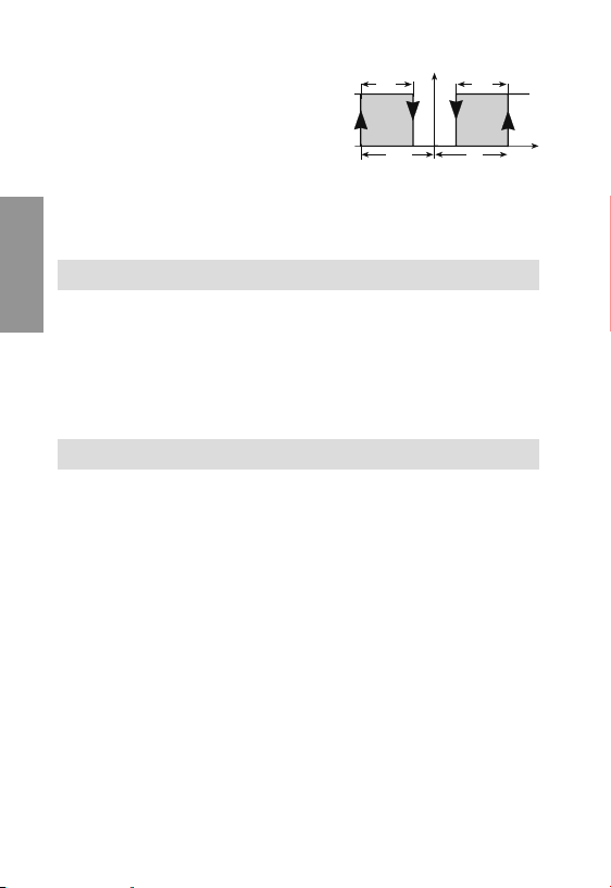
Neutral zone or Dead band
• Indicates an interval of values spanning
above and below the set-point, in which
the parameter regulated can change
without having to activate any output.
It is usually used in devices which, due to substantial system inertia, the set-
point can be exceeded even after the equipment is switched off, or to avoid the
overlapping of heating and cooling actions.
OFF
OFF
Direct Mode
ON
D
Set
Set + Diff
Temperature
Reverse Mode
ON
R
Set - Diff
Set
Temperature
English
- 33 -
User Manual – Thermoregulator FHT

No output is activated within
the dead band; outside
the dead band the device
operates by direct action
if the parameter controlled
increases and by reverse
action if it decreases.
ON
OFF
Set - Diff (R) - ZN
PWM operating mode
(time-controlled proportionate)
• Dead-band operation
featuring relays activated
periodically by impulse
(settable timing, see Output
English
menu).
The PWM mode modulates
the power based on the
position of the parameter
within the differential (power
increases as deviation from
set-point increases).
Warning: Not recommended for use with compressors, as this would cause
short start/stop periods.
Direct operating mode [PRO=0]
• When in this mode, all outputs
operate in direct.
Set-point 1 [ST1] and
differential 1 [DF1] must be
assigned values.
Hysteresis is to the right of
the set-point.
If both outputs are used, the
hysteresis of each output is
equal to half of the differential.
In this case output 1 will turn on when the parameter measured reaches value
[ST1]+[DF1]/2; output 2 will turn off on reaching this value.
ON
OFF
Set - Diff (R) - ZN
OUT 1
ON
D
OFF
Diff. 1
Set 1
1 output 2 outputs
Reverse
operating mode [PRO=1]
• When in this mode, all outputs
operate in reverse.
Set-point 1 [ST1] and
differential 1 [DF1] must be
assigned values.
Hysteresis is to the left of the
set-point.
User Manual – Thermoregulator FHT
OUT 1
ON
R
OFF
Diff. 1
1 output 2 outputs
- 34 -
Set 1
R
R
Mode PRO=0
Mode PRO=1
Dead band Mode
ZN
ZN
Set
Temperature
PWM Mode
ZN
ZN
Set
Temperature
OUT 1
ON
D
OFF
Set 1
OUT 2
ON
R
OFF
D
Set + Diff (D) + ZN
D
Set + Diff (D) + ZN
OUT 2
Diff. 1
OUT 1
Diff. 1
D
R
Set 1

If both outputs are used, the hysteresis of each output is equal to half of the
differential. In this case output 1 will turn on when the parameter measured reaches
the value [ST1]-[DF1]/2; output 2 will turn off on reaching this value.
Dead-band operation mode [PRO=2]
• When in this mode output 1 operates in reverse and output 2 in direct.
It is necessary to confi gure parameters set-point 1 [ST1], differential 1 [DF1] and
dead band [DBN], which typify both outputs.
The regulator will tend to keep the parameter within the dead band. Outside the dead
band output 2 will turn on if the parameter tends to increase; conversely output 1
will turn on if the parameter tends to decrease. If only one output is present, it will
operate in reverse, with the hysteresis to the left of the value [DBN].
Mode PRO=2
OUT 1
ON
R
OFF
PWM operating mode [PRO=5]
• The regulation logic of this operating mode is the same as that of the dead band
operating mode.
It is therefore necessary to confi gure parameters set-point 1 [ST1], differential 1
[DF1] and dead band [DBN], which typify both outputs. When in this operating mode,
relays are activated by impulses with the timing given by value [TCL] (see output
menu).
During that period the relay remains on for a variable length of time that is
proportionate to parameter deviation from the set-point (considering the dead band
when present). Beyond the differential value, the relay remains active 100% of the
time.
ON
OFF
ZN
Diff. 1
Set 1
1 output 2 outputs
Mode PRO=5
OUT 1
ZN
R
Diff. 1
Set 1
1 output 2 outputs
User Manual – Thermoregulator FHT
OFF
OFF
OUT 1
ON
R
Diff. 1
OUT 1
ON
R
Diff. 1
- 35 -
OUT 2
D
ZN
ZN
Diff. 1
Set 1
OUT 2
ZN
ZN
D
Diff. 1
Set 1
English

Operating mode with Direct/Reverse change-over
from digital input [PRO=6]
• When in this mode both outputs operate in direct (with set-point 1 and differential
1) or both in reverse (with set-point 2 and differential 2) depending on digital input
status.. More precisely, in direct if the digital output is open and in reverse if it is
closed. Operating functions are the same as in modes 0 and 1. Therefore both setpoints [ST1] and [ST2] and both differentials [DF1] and [DF2] must be confi gured.
Mode PRO=6
OUT 1
ON
Digital
input
English
Direct operating mode with set-point and differential change-over
from digital input [PRO=7]
• When in this mode both outputs operate in direct, with set-point 1 /differential 1
or set-point 2/differential 2) depending on digital input status. More precisely, with
set-point 1/differential 1 if the digital input is open and set-point 2/differential 2 if it
is closed. Operating functions are the same as in mode 0. Both set-points [ST1] and
[ST2] and both differentials [DF1] and [DF2] must be confi gured.
open
Digital
input
closed
Digital
input
open
Digital
input
closed
D
OFF
Diff. 1
Set 1
OUT 1
ON
R
OFF
Diff. 2
Set 2
1 output 2 outputs
OUT 1
ON
Mode PRO=7
D
OFF
Diff. 1
Set 1
OUT 1
ON
D
OFF
Diff. 2
Set 2
1 output 2 outputs
- 36 -
User Manual – Thermoregulator FHT
OFF
OFF
OFF
OFF
OUT 1
D
OUT 2
R
OUT 1
D
OUT 1
D
Diff. 1
Diff. 2
Diff. 1
Diff. 2
OUT 2
D
OUT 1
R
Set 2
OUT 2
D
OUT 2
D
ON
Set 1
ON
ON
Set 1
ON
Set 2

Reverse operating mode with set-point and differential change-over
from digital input [PRO=8]
• When in this mode both outputs operate in reverse, with set-point 1 /differential 1 or
set-point 2/differential 2, depending on the status of the digital input. More precisely,
with set-point 1/differential 1 if the digital input is open and set-point 2/differential 2
if it is closed.
Operating functions are the same as in mode 1. Therefore both set-points [ST1] and
[ST2] and both differentials [DF1] and [DF2] must be confi gured.
Digital
input
open
Digital
input
closed
Mode PRO=8
OUT 1
ON
ON
R
OFF
Diff. 1
Set 1
OUT 1
ON
OFF
ON
R
OFF
Diff. 2
Set 2
1 output 2 outputs
OFF
OUT 2
R
OUT 2
R
Diff. 1
Diff. 2
OUT 1
R
Set 1
OUT 1
R
Set 2
Operating mode with outputs 1 and 2 respectively in reverse with
set-point 1 and diff.1 and direct with set-point 2 and diff. 2 [PRO=9]
• When in this mode output 1 operates in reverse and output 2 in direct.
It is necessary to confi gure set-points 1 [ST1] and differential 1 [DF1] for output 1,
and set-point 2 [ST2] and differential 2 [DF2] for output 2.
Operating functions are the same as in modes 0 and 1.
If only one output is present it will operate in reverse.
English
Mode PRO=9
OUT 1
ON
R
OFF
Diff. 1
Set 1
1 output 2 outputs
Alarm operating mode [PRO=10]
• When in this mode output 1 operates in reverse (with dead band) whilst output 2 is
reserved for the alarm.. It is necessary to confi gure set-point 1 [ST1], differential 1
User Manual – Thermoregulator FHT
OFF
OUT 1
ON
R
Diff. 1
Set 1
- 37 -
Set 2
OUT 2
D
Diff. 2
ON
OFF
[DF1] and dead band [DB1] for output
1, and all parameters on the alarm menu
for output 2. The maximum alarm trips
when the value [ST1]+[HIA] is reached
and is disengaged on reaching value
[ST1]+[HIA]-[DFA]. The minimum alarm
trips when the value [ST1]-[LOA] is
reached and is disengaged on reaching
value [ST1]-[LOA]+[DFA].
When only one output is provided, it will be reserved for the alarm with the same
functions.
Alarm ON
Alarm OFF
DFA
LOA
Mode PRO=10
Set 1
Alarm output
DFA
HIA
English
Normal operation
Operation when parameters are not being programmed/confi gured.
When in this status, the device effects regulation based on the temperature
measured and the parameters set. The information displayed is:
• Temperature measured by the sensor
• Status of output OUT1 and, in devices with two outputs, OUT 2
OPERATION
SETTING REGULATION PARAMETERS
There are two types of programming for regulation parameters:
- Simple programming
- Advanced programming
Note: to restore default factory-set values, turn on the device while
pressing the “OK” key.
Simple programming
To change parameters in the Regulation menu [REG] only. This programming is
accessed by pressing the“OK” key.
Depending on the selected operating mode, the following parameters can be
confi gured (see System menu [SYS]):
– set, differential, regulation ON/OFF, minimum sensor reading, maximum sensor
reading
Parameter labels can be scanned in a circular motion by using the “up” (▲) key. To
exit the menu and return to normal operation, press the “down” (▼) key at any time
- 38 -
User Manual – Thermoregulator FHT

(which occurs automatically if no key is pressed for at least 40 s). To switch from
parameter label reading to the reading of the relevant numeric value, press the “OK”
key.
To change a parameter:
- from label or value reading, hold the “OK” key pressed for at least three seconds.
- the display will begin to fl ash the parameter value.
- use the “up” (▲) and “down” (▼) keys respectively to increase or decrease said
value.
- press the “OK” key to confi rm the change and exit (the display will stop
fl ashing).
Note: if no key is pressed within 40 seconds, the device will quit parameter
confi guration and no changes will be stored.
During the display and change of parameters the device will continue
operating with the previous settings.
If “password 1” is enabled (access password for the protection of settings - see
system menu), the display will read “- - - ” when the “OK” key is pressed from
normal status.
To proceed with parameter confi guration, enter the previously set password (a
numeric value from 0 to 255) using the “up” (▲) and “down” (▼) keys and then
press “OK” to confi rm.
If the password entered is correct the regulation menu will appear; otherwise normal
status will return.
Advanced programming
To enter advanced programming from normal status, press the “up” (▲) and
“down” (▼) keys simultaneously for at least 3 seconds.
Note: to restore factory-set default values, turn on the device while
pressing the “OK” key.
These parameters are classifi ed by type into nine menus:
1) Regulation (indicated by label [REG]): set-point, differential, dead band
2) Output (indicated by label [OUT]): timing of output activation, timing of
PWM cycle
3) Digital input (indicated by the label [ING]): function, delay time
4) Alarm (indicated by label [ALR]): probe alarm output status, minimum/maximum
shift, differential, delay time, buzzer on/off
5) Display (indicated by label [DSP]): set-point limits, probe offset, resolution,
measurement unit, reading fi lter
6) Sensor (indicated by label [SNS]): sensor type, sensor parameters
7) System (indicated by label [SYS]): password, change enabling, operating mode
English
- 39 -
User Manual – Thermoregulator FHT

8) Analog output (indicated by label [ANG]): type of analog output
9) Advanced (indicated by label [ADD]): dependency, type, insertion,
differential/logic
All the parameters within the nine menus and their corresponding values, are listed
in the following section.
- To scan the nine menus in sequence use the “up” (▲) key
- To enter the selected menu press the “OK” key
- Confi gurable parameter labels can be scanned within each menu by pressing
the “up” (▲) key; to view a parameter value press “OK” (to view parameter label
again press the “OK” key one more time).
- To change the parameter value, hold the “OK” key pressed for at least three
seconds.
- The parameter value will begin fl ashing: increase/decrease using the “up” (▲) and
English
“down” (▼) keys respectively.
- To confi rm the change press “OK”.
The parameter will stop fl ashing and the new value will be displayed
- It is possible to return to normal operation at any time by pressing the “down” (▼)
key (or not pressing any key for at least 40 seconds)
Note: if when confi guring parameters no key is pressed within 40 seconds
, the parameter label will be displayed again and none of the changes
entered will be saved.
Note: During the display and change of parameters the device will continue
operating with the previous settings.
If “password 2” has been enabled (access password for the protection of
settings - see system menu), the display will read “- - - ” when the “up”
(▲) and “down” (▼) keys are simultaneously pressed for three seconds from
normal status.To proceed with parameter confi guration, enter the password
previously set (a numeric value from 0 to 255) using the “up” (▲) and “down”
(▼) keys and press “OK” to confi rm.
If the password is correct the fi rst menu label will appear, otherwise normal status
will return.
PARAMETER MENU
To simplify device programming, parameters have been classifi ed into the following
various menus:
— [REG] regulatation menu
— [OUT] output menu
- 40 -
User Manual – Thermoregulator FHT

— [ING] external input menu
— [ALR] alarm menu
— [DSP] view menu
— [SNS] sensor menu
— [SYS] system menu
— [ANG] analog output menu
— [ADD] special parameter setting me
Parameter description
The tables show parameter labels in the same order in which they appear in the
various menus of the device.
[REG] regulation menu
Confi gurable Parameter
parameter Description unit value default notes
labels min max
ST1 set-point 1 degrees LO1 HI1 20.0 (1)
DF1 set-point 1 differential degrees 0.1 100 2.0
ST2 set-point 2 degrees LO2 HI2 30.0 (2)
DF2 set-point 2 differential degrees 0.1 100 2.0 (2)
DBN neutral zone (dead band) degrees 0 100 2.0 (2)
I-O regulation on/off - on (3)
HIO maximum value measured
by sensor 0 degrees --- (4)
LOO minimum value measured
by sensor 0 degrees --- (4)
HI1 maximum value measured
by sensor 1 degrees --- (4)
LO1 minimum value measured
by sensor 1 degrees --- (4)
Note:
(1) for values LO1/2 and HI1/2 see display menu [DSP]
(2) parameter is active only if it applies to the operating mode
(3) turns regulation on/off from keypad if ON there is normal operationif OFF:
- display reads “OFF”
- relays 1 and 2 take on status as established by parameter [SUI], menu [ING],
respecting the timing of menu [OUT]
(4) Maximum/minimum value read by sensors 0 and 1 is stored in these parameters.
The value can be reset by pressing the OK key for about 3 seconds (which starts a
new parameter updating control)
English
- 41 -
User Manual – Thermoregulator FHT

[OUT] output menu
Confi gurable Parameter
parameter Description unit value default notes
labels min max
ETR relay time control activation - 0 0 3 (5)
DON minimum time between
2 starts of same relay min 0 200 0 (6)
TOF minimum ON time
of relay min 0 200 0 (7)
TON minimum OFF time
of relay min 0 200 0 (8)
INI initial delay
English
from device start min 0 200 0 (9)
TCL PWM cycle time sec 1 200 200 (10)
Note:
(5) this parameter enables the control of times set in DON, TOF, and TON for each
output as follows:
0 timing disabled for both relay outputs
1 timing enabled only for relay 1 output
2 timing enabled only for relay 2 output
3 timing enabled for both relay 1 and 2 outputs
(6) this parameter restricts the number of starts per hour for the equipment connected
to the device (parameter frequently used e.g. for compressors)
(7) minimum time in which output must remain ON
(8) minimum time in which output must remain OFF
(9) output activation delay time from reset of the device
(10) the period that can be set for PWM regulation. This reading is displayed only if the
operating mode selected is PRO=5 (see system menu).
[ING] outside input menu
Confi gurable Parameter
parameter Description unit value default notes
labels min max
TID digital input function - 0 4 0 (11)
DID digital input delay min 0 200 0 (12)
SUI output status with
dig. input enabled (open) - 0 3 0 (13)
Note:
(11) Confi gurable values are: 0 disabled
User Manual – Thermoregulator FHT
- 42 -

1 external alarm (with open contact) with “DID” delay time and automatic reset
after alarm goes off.Output status then turns to “SUI”
2 manual-reset external alarm (with open contact).
3 input acts as switch: device is on when contact is closed and off when contact is
open
4 input acts as display change-over between probes S0 and S1 (open contact - S0
probe, closed contact - S1 probe)
Digital input function is excluded when one of the following operating
modes is selected in the system menu [SYS]: mode=6, mode=7 and
mode=8
(12) the delay after which the device responds to a signal received from the digital input
(13) when the digital input is active and “DID” time has elapsed, the output may take on
the following status:
0 both relays OFF
1 relay 1 ON and relay 2 OFF
2 relay 1 OFF and relay 2 ON
3 both relays ON
[ALR] alarm menu
Confi gurable Parameter
parameter Description unit value default notes
labels min max
SUA output status
in probe alarm condition - 0 3 0 (14)
LOA minimum alarm shift degrees 0.1 100 50 (15)
HIA maximum alarm shift degrees 0.1 100 50 (15)
DFA alarm differential degrees 0.1 100 2
TRA alarm activation delay time min 0 200 0
SUO buzzer activation - no yes no (16)
EAC timed alarm message
activation - no yes no (17)
RAR automatic relay reset and min/max
alarm message reset on alarm end - no yes yes (18)
RAA automatic min/max alarm
message reset on alarm end - no yes yes (19)
TRP min/max alarm generation delay
from power-on hours 0 15 0 (20)
English
Note:
(14) output status when in probe alarm condition (see note n°13)
(15) value to be added or subtracted to the established set-point, respectively for
maximum or minimum alarm
- 43 -
User Manual – Thermoregulator FHT

(16) if “yes” both key beep and alarm-condition buzzer are enabled. If “no” both are
disabled
(17) If “yes” the type of alarm is displayed even during timing of the same, if “no” the
type of alarm is displayed only after the timing
(18) if “yes”, at the end of a min/max alarm it will be necessary to dismiss alarm type
reading and reset the relay manually
(19) if “yes”, at the end of a min/max alarm it will be necessary to dismiss alarm type
reading manually (the relay will automatically reset instead)
(20) blocks the generation of max/min alarms for a period
[DSP] view menu
Confi gurable Parameter
parameter Description unit value default notes
English
labels min max
LO1 lower limit of set-point 1 degrees -99 HI1 -99
HI1 upper limit of set-point 1 degrees LO1 999 999
LO2 lower limit of set-point 2 degrees -99 HI2 -99 (21)
HI2 upper limit of set-point 2 degrees LO2 999 999 (21)
SOF probe 1 calibration offset degrees -50 +50 0.0 (22)
SIF probe 2 calibration offset degrees -50 +50 0.0 (22)
RIS reading resolution - HI LO HI (23)
UNI temperature measurement unit - C F C (24)
FIL measurement fi lter - no yes yes (25)
Note:
(21) parameter is active only if it applies to the operating mode
(22) value added to the measure to compensate for an inaccuracy of the same
(23) reading resolution:
0.1 if “HI” or 1.0 if “LO”
(24) Attention: when unit of measurement is changed, parameter settings are not
converted automatically and must be recalibrated.
(25) if the parameter is set to “yes” a moving average of 8 measurement values (i.e. of
about 4 seconds) is calculated, if “no” the average is not calculated
- 44 -
User Manual – Thermoregulator FHT

[SNS] sensor menu
Confi gurable Parameter
parameter Description unit value default notes
labels min max
TYO sensor type 0 - 0 16 (26)
TY1 sensor type 1 - 12 16 (27)
S01 display of sensor 1 or 2 - S0 S1 S0 (27)
Note:
(26) default parameter and sensor values depend on device model. All sensors available
are listed as follows:
Temperature probes NiPt
sensor type display reading
Pt100 (*) PtE (*)
Ni100 nI
* Device default setting
Thermocouples JK
sensor type display reading
J J
K C
L L
T t
E E
N n
R r
S s
Linear probes
sensor type display reading
0-20mA 020
4-20mA 420
0-1V 0-1
User Manual – Thermoregulator FHT
English
- 45 -

Temperature probes NTC
sensor type display reading
(**) nt0
(**) nt1
type 4 nt2 (*)
(**) CSt
* Device default setting, which corresponds to the use of temperature probe NTC
code VN870200 (see “Red line” in catalogue under the section Thermoregulation
- temperature probes)
** When using sensors other than “type 4” as noted above (see note *), it is possible
to select one of the three items “nt0, nt1, Cst” corresponding to probes with
different temperature/resistance ratios. In these cases, in order to identify the
type of sensor to be selected, we recommend contacting the Technical Assistance
English
Service Department directly.
(27) parameter displayed only on models NTC
[SYS] system menu
Confi gurable Parameter
parameter Description unit value default notes
labels min max
PS1 password 1 - 0 255 0 (28)
PS2 password 2 - 0 255 0 (28)
NEN enables parameter changing - yes no no (29)
PRO operating mode - 0 12 0 (30)
ADR serial address - 1 247 1
COM serial communication
parameters - 0 11 0 (31)
Note:
(28) password is enabled if setting is other than 000
(29) if setting is “yes” all other parameters can be viewed but not changed
(30) the following operating modes are possible:
0 relay output 1 and 2 in direct with set-point 1 and differential
1 (hysteresis to the right of the set-point)
1 relay output 1 and 2 in reverse with set-point 1 and differential
1 (hysteresis to the left of the set-point)
2 dead band with relay output 1 in reverse and relay output 2 in direct, set-point 1
and differential 1
3 same as in mode 0 but with differential centered on set-point
4 same as in mode 1 but with differential centered on set-point
- 46 -
User Manual – Thermoregulator FHT

0 960 9600 baud ODD parity 1 stop
1 480 4800 baud ODD parity 1 stop
2 240 2400 baud ODD parity 1 stop
3 120 1200 baud ODD parity 1 stop
4 96E 9600 baud EVEN parity 1 stop
5 48E 4800 baud EVEN parity 1 stop
6 24E 2400 baud EVEN parity 1 stop
7 12E 1200 baud EVEN parity 1 stop
8 96N 9600 baud EVEN parity 2 stop
9 48N 4800 baud EVEN parity 2 stop
10 24N 2400 baud EVEN parity 2 stop
11 12N 1200 baud EVEN parity 2 stop
5 PWM regulation with relay output 1 in reverse and relay output 2 in direct,
set-point 1 and differential 1 plus dead band if applicable
6 change-over between outputs in direct (with set-point 1 and differential 1) and
outputs in reverse (with set-point 2 and differential 2) from digital input
7 outputs in direct with change-over between set-point 1/differential 1 and set-
point 2/differential 2 from digital input
8 outputs in reverse with change-over between set-point 1/differential 1 and set-
point 2/differential 2 from digital input
9 relay output 1 in reverse with set-point 1 and differential 1 and output relay
2 in direct with set-point 2 and differential 2
10 if one relay output: alarm function if two output relays: relay output 1 in
reverse (with set-point 1, differential 1 and dead band) and relay output 2
in alarm
11 – (not available)
12 special mode
(31)
Parameter value serial parameter
In order to make internet connections easier, the following meaning applies to
status information found in the COM menu for OUT1 and OUT2 output:
- OUT1: if lit it indicates accurate reception of bus frame with the parameters set
- OUT2: if lit it indicates serial transmission is in process
English
- 47 -
User Manual – Thermoregulator FHT

[ANG] analog output menu
Confi gurable Parameter
parameter Description unit value default notes
labels min max
ANT type of analog output - 0 2 0 (32)
ALO value corresponding
to lower limit degrees -99 999 00.0 (33)
AHI value corresponding
to upper limit degrees -99 999 100 (33)
Note:
(32)
Analog output display reading
English
voltage 0-10 V 0-1
amperage 0-20 mA 020
amperage 4-20 mA 420
(33) it is possible to set an output range with AHI less than ALO to allow the output to
decrease with the increase of the measured parameter
[ADD] special parameters menu
Confi gurable Parameter
parameter Description unit value default notes
labels min max
DP0 output 1 dependency - 0 10 (34)
TI0 on/off type or PWM 1 - 0 1 (35)
DB0 dead band 1 - 0 1 (36)
IN0 cut-in 1 % -100 +100 (37)
DF0 logic 1 differential % -100 +100 (38)
DP1 output 2 dependency - 0 10 (34)
TI1 on/off type or PWM 2 - 0 1 (35)
DB1 dead band 2 - 0 1 (36)
IN1 cut-in 2 % -100 +100 (37)
DF1 logic 2 differential % -100 +100 (38)
Note:
(34) the parameter establishes in what way an output depends on a set-point or alarm
function. The values take on the following meanings:
0 output not active
1 output relative to set-point 1
2 output relative to set-point 2
3 change-over between output in direct (with set-point 1 and differential 1) and
output in reverse (with set-point 2 and differential 2) by means of digital input
(open - direct, closed - reverse).
- 48 -
User Manual – Thermoregulator FHT

onaila
tI
1 Channel
Operating mode
Parametro 012345 67 8910
IN0 100 -100 -100 50 -50 -100 * 100 -100 -100 0
DF0 -100 100 100 -100 100 100 * -100 100 100 100
IN1 100 -100 100 50 -50 100 * 100 -100 100 0
DF1 -50 50 -100 -50 50 -100 * -50 50 -100 100
2 Cannel
Operating mode
Parametro 012345 67 8910
IN0 50 -50 -100 0 0 -100 * 50 -50 -100 -100
DF0 -50 50 100 -50 50 100 * -50 50 100 100
IN1 100 -100 100 50 -50 100 * 100 -100 100 0
DF1 -50 50 -100 -50 50 -100 * -50 50 -100 100
4 change-over between set-point 1/differential 1 and set-point 2/differential 2 by
means of digital input (open – set 1, closed set 2)
5 output related to set-point 2 maximum alarm
6 output related to set-point 2 minimum alarm
7 output related to set-point 1 maximum alarm
8 output related to set-point 1 minimum alarm
9 output related to set-point 1 maximum/minimum alarm
10 output related to set-point 2 maximum/minimum alarm
(35) establishes whether the type of regulation is ON/OFF (value 0) or PWM (value 1)
(36) indicates if dead band is present (value 1) or not (value 0)
(37) indicates change-over point ON of relay compared to set-point set by
“dependency” parameter: the change-over point is calculated adding an “INO”
percentage of the differential (from -100% to +100%) to the set-point.
(38) indicates change-over point OFF of relay compared to the point where ON
change-over took place: the change-over point OFF is calculated adding a “DF0”
percentage of the differential (from -100% to +100%) to the ON-point.
Note: default values of these parameters depend on the operating mode and
number of channels, as indicated in the tables below:
English
* Default values for mode 6 are the same as in modes 0 and 1 based on direct or
reverse functionning of outputs.
- 49 -
User Manual – Thermoregulator FHT

ERROR MESSAGES
• In case of alarm or malfunction, measure reading and alarm type reading may be
displayed alternately.
Operating alarm/error messages are described in the following table.
Message Type of error Output status
ER0 Sensor 1 disconnected or short-circuted Same as in parameter (SUA)
ER1 Sensor 2 disconnected or short-circuted Same as in parameter (SUA)
ALL Minumim alarm Depending on operation mode
ALH Maximum alarm Depending on operation mode
ALE External input alarm Same as in parameter (SUA)
OFF Regulation blocked by external input Same as in parameter (SUA)
English
Note:
The “OFF” message does not switch to the measure reading, but remains fi xed on
the display
SERIAL COMMUNICATION
• The device is fi tted with an isolated serial output RS-485
• The data communication system is based on MODBUS protocol and can be
connected to a Master system (PC/PLC)...) on a multipoint line RS-485:
- up to 32 FHT’s (slaves) without signal amplifi ers, from a maximum distance
of 1000m
- up to 247 FHT’s (slaves) in groups of 32 separated by proper signal amplifi ers
• Communication occurs in half duplex and only the Master (PC/PLC...) can initiate
Query/Response type transaction with the Slaves (only one slave with address) or
directing the message to all the slaves (address 0) without receiving an answer
• The MODBUS protocol specifi cations are:
- Coding system: RTU (Remote Terminal Unit)
- Transmission speed (Baud Rate): 9600, 4800, 2400, 1200 bps (can be selected by
user)
- Byte format: 1 start bit, 8 data bits, 1 parity bit (can be selected):
none, odd or even, 1 stop bit
• Contact TAS (Technical Assistance Service dept.) to request documents regarding
MODBUS functions and use of registers.
- 50 -
User Manual – Thermoregulator FHT

REFERENCE STANDARDS
■ For safety: EN 60730-2-9
■ For electromagnetic compatibility:
EN 55014-1
EN 55014-2
EN 61000-6-2
EN 61000-6-3
English
- 51 -
User Manual – Thermoregulator FHT

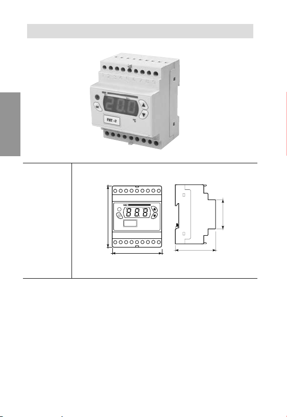
DIMENSIONS OF BACKBOARD MODEL 33x75 mm
o
nailatI
English
FHT-1P3D
FHT-2P3D
FHT NTC-2P3D
OK
75
- 52 -
User Manual – Thermoregulator FHT
33
81
70
33
82

D3P1-THFledoMD3P2-THFledoMTHFledo
M
CTN D
3
P2-
nailaI
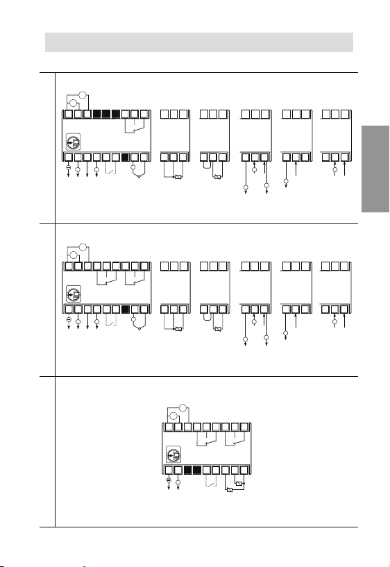
DIAGRAMS FOR 33x75mm BACKBOARD
Wiring diagram
Analog
output
0÷10V
RS-485
4÷20 mA
+
11
i
e
a
r
l
S
1
2346
Relay output
8(5)A/250 V~
RS-485
+
i
e
a
r
l
S
2
Relay output 1
8(5)A/250 V~
+
12 131510
14
16 17 18
5
7
89
7
7
8
8 9
6
+
~
A
e
l
i
n
m
o
i
e
z
n
a
t
External
External
Probe input
Probe
consent
consent
PTC 3 wires
input
input
TC
Analog
output
0÷10V
4÷20 mA
+
Output relay 2
8(5)A/250 V~
131510
141112
16 17 18
5
3 461
7
8 9
+
~
A
e
l
i
n
m
o
i
e
z
n
a
t
Probe
External
consent
input
TC
input
7
89
6
Probe input
External
consent
PTC 3 wires
input
input
RS-485
+
10
11
r
i
a
e
l
S
9
6
Jumper
Probe
External
consent
input
input
PTC
2 wires
7
89
6
Jumper
Probe
External
consent
input
input
PTC
2 wires
13
1412
15
7
89
6
6
+
Probe input
0÷1V
+
4÷20 mA
External
0÷20 mA
-
consent
+
input
Active
probe
supply output
9VDC max 30 mA
6
+
supply output
9VDC max 30 mA
9VDC max 30 mA
7
8 9
6
+
Probe input
0÷1V
+
4÷20 mA
External
0÷20 mA
-
consent
input
Active
probe
9VDC max 30 mA
Sensor - 3 wires to be powered Sensor - 2 wires to be powered
Sensor - 3 wires to be powered Sensor - 2 wires to be powered
Output relay 2
8(5)A/250 V~
16 17 18
89
External
consent
input
8
External
consent
input
7
9
8
6
+
Probe input
0÷1V
External
4÷20 mA
consent
0÷20 mA
input
89
English
External
consent
input
Self-powered sensor
7
9
6
+
Probe input
0÷1V
4÷20 mA
0÷20 mA
Self-powered sensor
7
Input
probe
4÷20 mA
0÷20 mA
Active
probe
supply output
7
Input
probe
4÷20 mA
0÷20 mA
Active
probe
supply output
A
l
i
m
- 53 -
5234
7
8 9
6
NTC1
NTC2
~
e
n
o
i
e
z
n
a
t
NTC probe
input
External
consent
input
1
Output relay 1
8(5)A/250 V~
User Manual – Thermoregulator FHT
onailatI
English
FHT-1DA
FHT-2DA
FHT NTC-2DA
DIMENSIONS OF 4 DIN MODULAR MODEL
8
7
6
345
2
1
OK
7
8
121314
11
10
9
17
16
15
18
70
65
54
- 54 -
User Manual – Thermoregulator FHT
onaila
tI
AD1-THFledoMAD2-THFledoMTH
FledoM
C
TN AD2-
DIAGRAMS FOR BACKBOARD 4 DIN MODEL
Wiring diagram
V
0
3
~
2
~
V
~
4
5
2
z
0
H
-
0
6
~
5
z
0
H
-
6
0
1
r
a
i
e
l
S
10
11
+
RS-485
V
0
3
2
~
V
~
4
5
2
0
-
6
0
~
5
z
0
H
-
6
0
1
2
r
a
i
e
l
S
10
11
+
RS-485
12 13
Analog
output
0÷10V
4÷20 mA
~
z
H
34
12 13
Analog
output
0÷10V
4÷20 mA
+
Relay output 2
8(5)A/250 V~
+
Relay output
8(5)A/250 V~
5234
9
7
8
6
14
16
17 18
15
+
External
consent
TC probe
input
input
Relay output 1
8(5)A/250 V~
5
89
7
6
14
16
17 18
15
+
External
consent
TC probe
input
input
16
16
Probe input
PTC 3 wires
16
Probe input
PTC 3 wires
5
1
10
RS-485
17 18
17 18
2
~
0
-
S
17 18
Jumper
Jumper
V
0
3
~
2
~
V
~
4
5
z
0
H
-
0
6
Relay output 2
8(5)A/250 V~
z
H
0
6
4
3
2
r
a
i
e
l
13
12
11
+
16
Probe input
PTC 2 wires
+
Sensor - 3 wire to be povered
16
17 18
16
Probe input
PTC 2 wires
+
Sensor - 3 wire to be povered
Relay output 1
8(5)A/250 V~
5
89
7
6
14
16
17 18
15
NTC1
NTC2
External
consent
NTC probe
input
input
17 18
+
Probe input
4÷20 mA
0÷20 mA
Active
probe
supply output
9VDC max 30 mA
17 18
+
Probe input
4÷20 mA
0÷20 mA
Active
probe
supply output
9VDC max 30 mA
16
181617 18
17
181617 18
17
+
Probe input
0÷1V
4÷20 mA
0÷20 mA
Self-powered sensor
+
Probe input
0÷1V
4÷20 mA
0÷20 mA
Self-powered sensor
English
Probe
0÷1V
input
+
4÷20 mA
-
0÷20 mA
Active
probe
supply output
9VDC max 30 mA
Sensor - 2 wire to be povered
16
Probe
0÷1V
input
+
4÷20 mA
-
0÷20 mA
Active
probe
supply output
9VDC max 30 mA
Sensor - 2 wire to be povered
- 55 -
User Manual – Thermoregulator FHT

Vemer S.p.A.
I - 32032 Feltre (BL)
Via Camp Lonc, 16
Tel +39 0439 80638
Fax +39 0439 80619
e-mail: info@vemer.it - web site: www.vemer.it
V3ISO0330-010-072007
 Loading...