

VEM KPE Series, G10 Series, K10 Series, K20 Series, K21 Series Operating And Maintenance Instruction Manual
...
V
Operating and
Maintenance Instruction
Three Phase
Asynchronous motors
with squirrel cage
version II2G EEx d(e) IIC T 3-6
EM motors GmbH
Ausgabe 07.2005
I
Dezember 1996
0
y
.
R
5
Werknorm EW-N 120
EC-Certificate of Conformit
Blatt 1 Seite 2
VEM motors GmbH ab:1. 12. 1996
Carl-Friedrich-Gauß-Str. 1 verbindlich:
D-38855 Wernigerode bis:
The electrical apparatus
three-phase asynchronous motors with squirrel cage rotor
three-phase asynchronous motors with slip-ring rotor
of series
KP./KPE./K10./K11./K20./K21. G10./G11./G20./G21./GS10./GS11.
BP./BPE./B10./B11./B20./B21. CP./CPE./C10./C11.
AR. YP./YPE./Y10./Y11./Y20./Y21.
A10./A11../A20./A21
SP./SPE./S10./S11. S81.
WE1./W20./W21. M21. 132 up to 180 (MMGE..., EDU...)
R10./R11./R20./R21.
K22.. 355 / B22. 35
are in conformity with the instructions of
73/23/EWG
Low Voltage Directive
amended by RL 93/68 /EWG
K81R/K82R/B82
89/336/EWG
Directive about Electromagnetic Compatibility
amended by RL 91/263/EWG, 92/31/EWG and 93/68/EWG
The conformity with the instructions of these Directives is proved by the observation
of following standards:
European Standard German Standard / VDE-Classification
EN 50082-1:1997 DIN EN 50082-1/11.97 - VDE 0839-82-1/11.97
EN 61000-6-4:2001 DIN EN 50081-2/03.94 - VDE 0839-81-2/03.94
EN 55014-1:2001 DIN EN 55014-1/11.01 - VDE 0875-14-1/11.01
EN 55014-2:1997 DIN EN 55014-2/10.97 - VDE 0875-14-2/10.97
EN 61000-3-2:2000 DIN EN 61000-3-2/12.01 – VDE 0838-2/12.01
EN 61000-3-3:2001 DIN EN 61000-3-3/11.98 – VDE 0838-3/11.98
EN 60034-5:2001 DIN EN 60034-5/12.01 – VDE 0530-5/12.01
EN 60034-6:1993 DIN EN 60034-6/08.96 - VDE 0530-6/08.96
EN 60034-9:1997 DIN EN 60034-9/06.98 - VDE 0530 Teil 9/06.98
EN 60034-1:200 DIN EN 60034-1/09.00 - VDE 0530-1/09.00
EN 60034-2:1996 DIN EN 60034-2/09.98 - VDE 0530-2/09.98
DIN IEC 60038/05.87
Wernigerode, the..................
Sander Beutner
Manager Factory Manager
This certificate attests the conformity with the named Directives, however, it is not a promise
of properties in the meaning of product liability.
In case of electronical communication, the signature does not appear.
Erarb. Gepr. Genehm. Änderungszustand

Warning!
Hazardous electrical current!
Ensure protection against explosions!
Before installing
Make sure that device cannot be switched on again by accident.
Switch off the power to the device.
Make sure that the device is de-energized.
Connect to earth and short out.
Cover or close off any neighboring live parts with a barrier.
Follow carefully the assembly instructions provided for the device.
Only qualified personnel as per EN 50110-1/-2 (VDE 0105, part 100) can perform any work on this de-
vice/system.
The electrical connections are to be made as per the relevant specifications (e.g. cross-section of the supply
line, fuses, protective connection).
Opening the motor - save for the terminal box - during the warranty period without the manufacturer's permission
shall lead to the termination of the warranty.
Original spare parts are to be used for the approved repairs or repairs not falling under the warranty.
Live and rotating parts of electrical motors can cause major or deadly injuries.
Any shipping, installation, start-up and maintenance works are to be carried out only by qualified personnel (fol-
low carefully any regulations on explosion protection such as EN 60079-14 and EN 50821-1-2 as well as any
other national accident prevention regulations).
As regards any equipment subject to these guidelines, it is important to adopt the necessary safety precautions
to protect the personnel against possible injuries.
The personnel must be duly instructed to proceed with caution and according to regulations during shipping,
hoisting, and positioning and while repairing the motor.
Do not lift the motor together with the drive equipment by the motor lifting eyebolts.
Do not use the supplied lifting eye bolts at ambient temperatures below –20°C, in accordance with DIN 580.
Lower temperatures could lead to the ring screws breaking and consequent breaking and consequent injury to
personnel and/ or damage to the installation.
Do not load the eyebolts as per DIN 580 no more than 45° compared to the screwing direction. The use of
crossbeams is recommended. See the operating instructions for the layout dimensions of the lifting eyebolts and
the minimum dimensions of the loading crossbeams and chain lengths.
In the case of motors with built-in brake appropriate safety measures are to be adopted against the possible
failure of the brake especially in applications involving the pulling of loads.
Operating the motor with the supplied shaft protection cover alone is forbidden.
Contact with the capacitor for the start-up and running of single-phase motors is to be avoided until the unload-
ing procedure is carried out securely.
If a high-voltage test is necessary, the procedures and precautionary measures set forth in accident prevention
regulations are to be followed.
I

Physikalisch-technische Bundesanstalt PTB
Braunschweig und Berlin
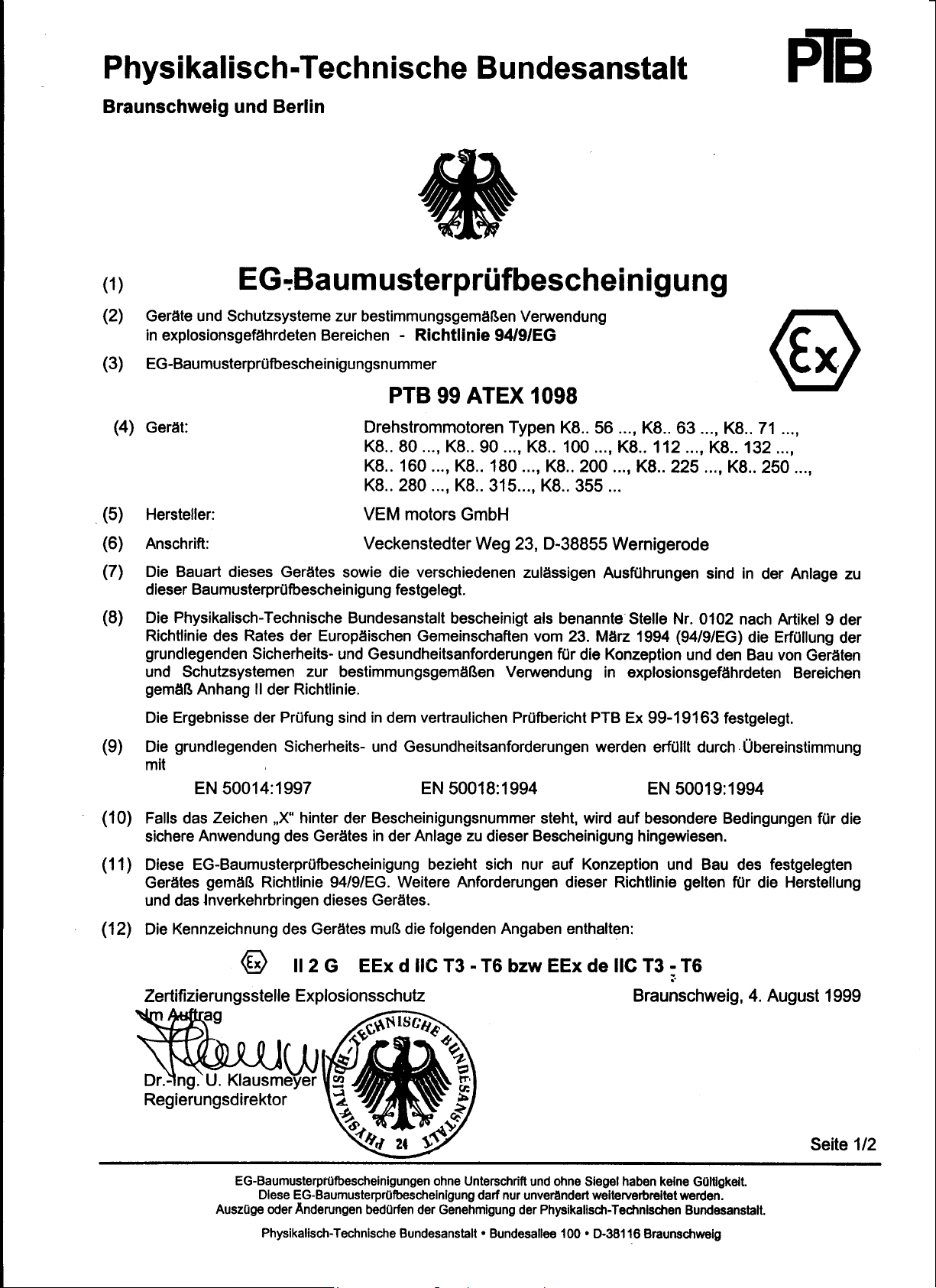
(1) EC-TYPE-EXAMINATION CERTIFICATE (Translation)
(2) Equipment and Protective Systems Intended for Use in Potentially Explosive Atmospheres –
Directive 94/9/EC.
(3) EC-type-examination Certificate Number:
PTB 99 ATEX 1098
(4) Equipment: Three-phase motor of the type series K8. 56..., K8.. 63..., K8.. 71...,
K8.. 80..., K8.. 90..., K8.. 100..., K8.. 112..., K8.. 132...,
K8.. 160..., K8.. 180..., K8.. 200..., K8.. 225..., K8.. 250...,
K8.. 280..., K8.. 315..., K8.. 355...
(5) Manufacturer: VEM motors GmbH
(6) Address: Veckenstedter Weg 23, D-38855 Wernigerode
(7) This equipment and any acceptable variation thereto are specified in the schedule to this
certificate and the documents therein referred to.
(8) The Physikalisch-Technische Bundesanstalt, notified body No.0102 in accordance with
Article 9 of the Council Directive 94/9/EC of 23 March 1994, certifies that this equipment
has been found to comply with the Essential Health and Safet y Requirements relating to the
design and construction of equipment and protective systems intended for use in potentially
explosive atmospheres, given in Annex II to the Directive.
The examination and test results are recorded in the confidential report PTB Ex 99-19163
(9) Compliance with the Essential Health and Safety Requirements has been assured by
compliance with
EN 50014:1997 EN 50018:1994 EN 50019:1994.
(10) If the sign „X” is placed after the Certificate number, it indicates that the equipment is
subject to special conditions for safe use specified in the scheduleto this certificate.
(11) This EC-type-examination Certificate relates only the design and construction of the
specified equipment in accordance with Directive 94/9/EG. Further requirements of this
Directive apply to the manufacture and supply of this equipment.
(12) The marking of the equipment shall include the following:
II 2 G EEx d IIC T3 – T6 or EEx de IIC T3 – T6
Zertifizierungsstelle Explosionschutz Braunschweig, 4 August 1999.
By order
(signature)
Dr.-Ing. U.Klausmeyer
__________________________________________________________________________________________________________________
EC-type-examination Certificates without signatu re and official stamp shall not be valid. The certificates may be circulated only without altera tion.
Extracts or alteriations are subject to approval by the Physikalisch -Technische Bundesansta lt. In case of dispute, the German text shall prevail.
Pysikalisch-Technische Bundesanstalt . Bundesallee 100 . D-38116 Braunschweig

Physikalisch-technische Bundesanstalt PTB
Braunschweig und Berlin
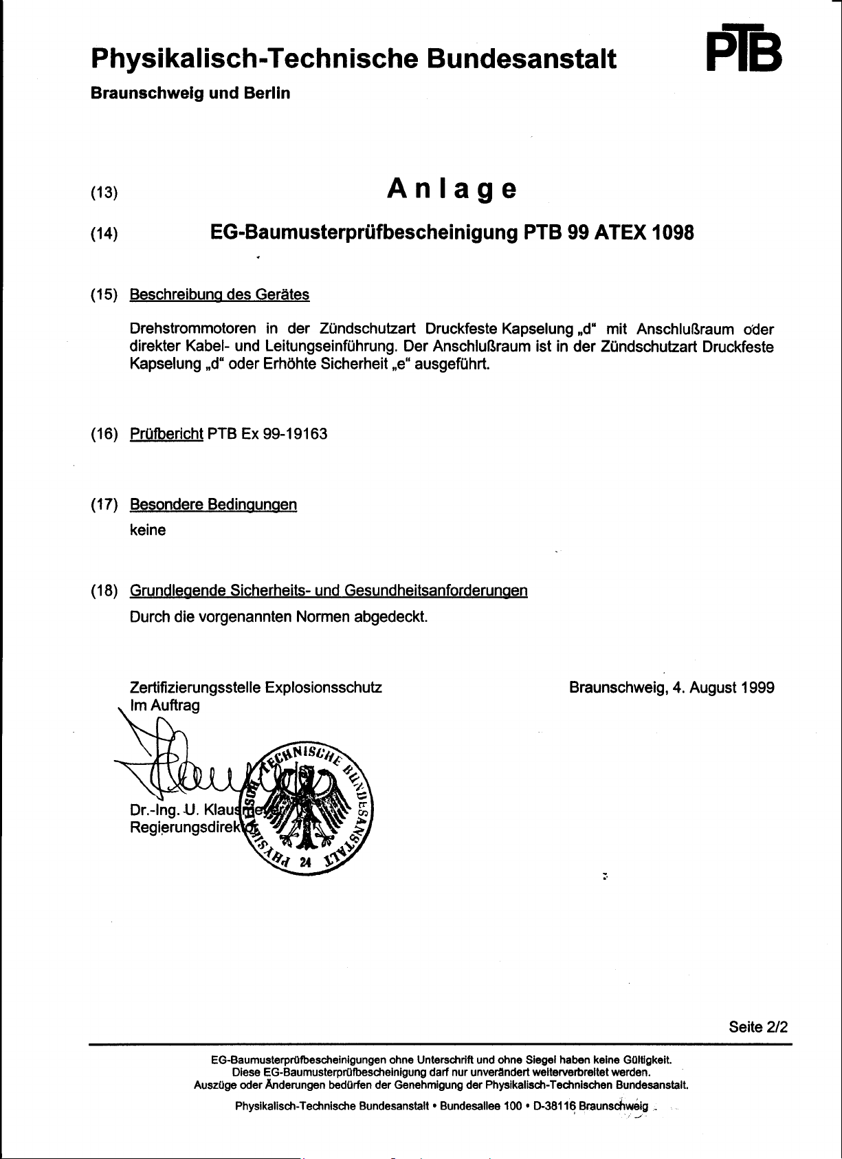
(13) Schedule
(14) EC-TYPE-EXAMINATION CERTIFICATE PTB 99 ATEX 1098
(15) Description of equipment
Three-phase motors of the type of protection flameproof safety „d” with terminasl
compartment or direct cable entries. The terminal compartment is carried out in the type of
protection flameproof enclosure „d” or increased safety „e”.
(16) Report PTB Ex 99-19163
(17) Special conditions for safe use
note
(18) Essential health and safety requirements
met by compliance with standards
Zertifizierungsstelle Explosionschutz Braunschweig, 4 August 1999.
By order
(signature)
Dr.-Ing. U.Klausmeyer
__________________________________________________________________________________________________________________
EC-type-examination Certificates without signatu re and official stamp shall not be valid. The certificates may be circulated only without altera tion.
Extracts or alteriations are subject to approval by the Physikalisch -Technische Bundesansta lt. In case of dispute, the German text shall prevail.
Pysikalisch-Technische Bundesanstalt . Bundesallee 100 . D-38116 Braunschweig
About this Manual
These operating instructions apply to AC motors of the following series:
K8.R and B8.R.
Besides the general assembly instructions, these guidelines are to be followed for the installation, start-up and maintenance of explosion-protected AC motors with a degree of protection of "pressure-resistant encapsulation" marked:
(II..), EEx de II. T or EEx d II. T.
Any independent manufacturing equipment mounted on or built into the motors like brakes, rotary encoders or frequency converters, etc. have their own operating instructions which are to be duly followed.
Target readership
This manual is addressed to the specialists in charge of installing, operating and servicing the motors. Besides conventional technical training they must possess knowledge in the field of explosion protection.
Abbreviations and symbols
This manual uses abbreviations and symbols having the following meanings:
indicates handling instructions
>
draws your attention to interesting tips and additional information
Please note!
warns against minor damages to property.
Caution!
warns against major damages to property and minor injuries.
Warning!
warns against major damages to property and major injuries or death.
1 Explosion-protected Motors
Intended use
The motors are to be operated only according to the data specified on the rating plate. According to the relevant
marking on the rating plate, the motors are fit for use in areas subject to explosion hazards.
The motors are fit to be built into another machine. Start-up is forbidden until the conformity of the final product with
Directive 89/392/EEC as amended by 98/37/EC is determined.
Liability and Warranty Guarantee
We cannot be held liable for any damage or malfunctions resulting from assembly errors, the failure to follow these
operating instructions or improper repairs.Original spare parts are manufactured and tested specifically for these
motors.
We recommend that you obtain any spare parts and accessories only from the manufacturer.
We hereby specify that any spare parts and accessories not supplied by the manufacturer require our approval.
Under any circumstances the mounting and use of third-party products can negatively affect the motor's original
structural properties and impair the safety for persons, the motor or other real values (explosion protection).
The manufacturer shall not be liable for any damages resulting from the use of spare parts or accessories not authorized by the manufacturer.Any unauthorized conversions and alterations to the motor shall not be approved for
safety reasons and the manufacturer cannot be held liable for any resulting damages.
Servicing
VEM customer service is available for all technical information concerning VEM motors.
Should a problem occur,contact us or one of our local branch offices.
When ordering spare parts, in addition to the listed designation of the part required, please indicate the motor type
and serial no.
Delivery, Storage, Transport
Delivery
>
Check the motor for damages during transportation.
In case of damage during transportation an investigation of fault is to be performed by the forwarding agent.
>
Report any covert damages to the forwarding agent or manufacturer no later than seven days from the transfer
of the motor.
The entire packaging material can be recycled by means of the Dual System.
Storage
Storage up to a maximum of 36 months is possible in the following conditions:
• In order to prevent a drop in the insulation resistance, the surrounding environment must be dry and dust-free.
• The room temperatures should not drop below +5 °C or exceed +30 °C with an air humidity of < 70 % and register
changes in temperature greater than 10 °C/day.
• In order to prevent damage during storage any occurring oscillations must amount to V
• For motors with regreasing systems repress an amount of grease double that specified on the motor at standstill
before storage.
Please note!
In case of storage conditions deviating from those specified above the measures set forth
in the separate storage instructions must be adopted.
Transport
Do not lift the motor together with mounted driven machines such as, for instance, pumps, gearing, etc. by the motor
lifting eyebolts.
Do not use eyebolts as per DIN 580 at ambient temperatures lower than –20 °C.
At these temperatures the eyebolts may break and hence injure the personnel and/or damage the machinery. Do not
load the eyebolts as per DIN 580 no more than 45° compared to the screwing direction. The use of crossbeams is
recommended. Layout dimensions of the lifting eyebolts and the minimum dimensions of the loading crossbeams
and chain lengths.
Please note!
When mounting vertical motors from the horizontal position, the shaft must not touch the
floor to avoid damaging the bearings.
< 0.2 mm/s.
eff
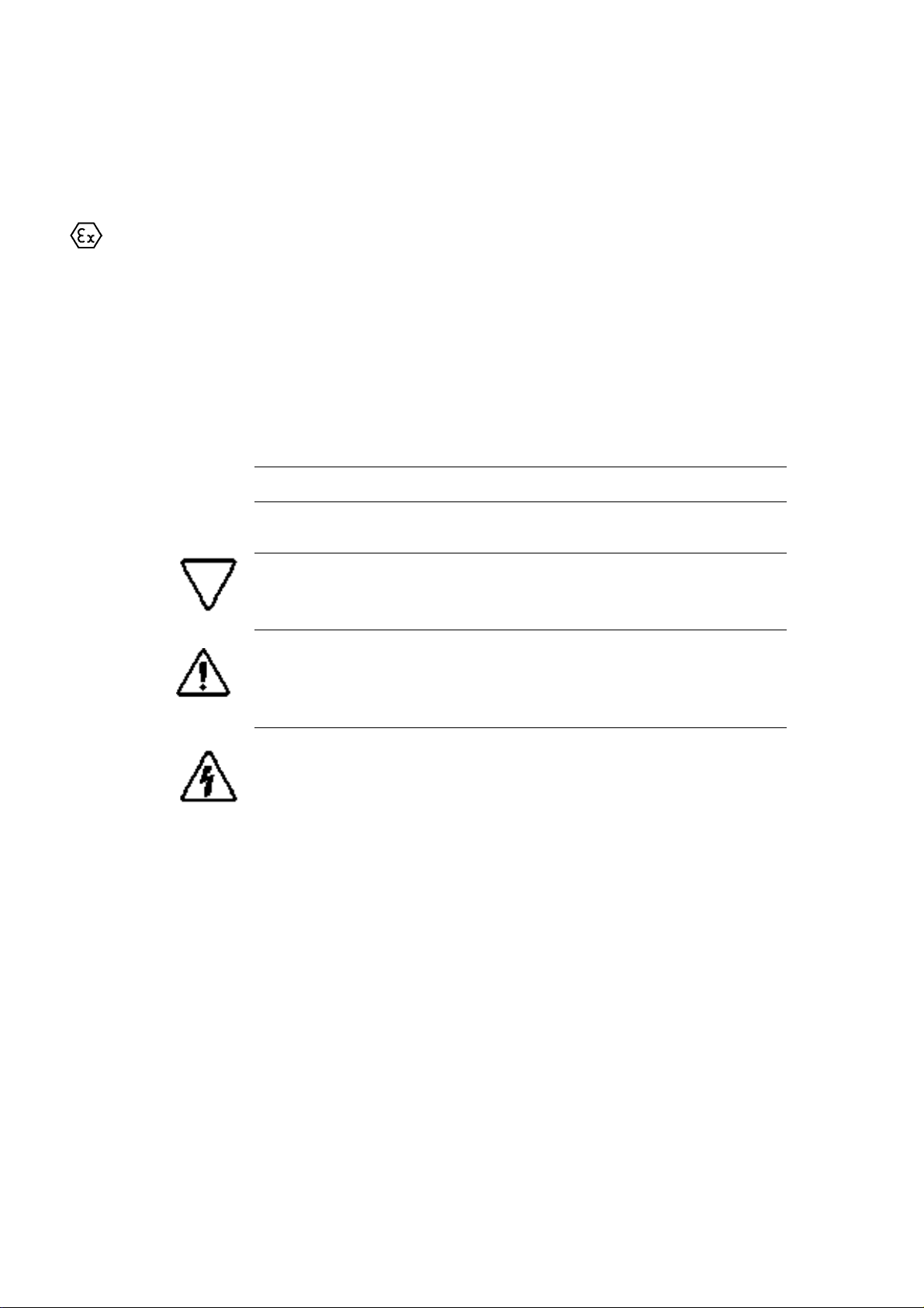
Figure 1: Eyebolt dimensions

Table 1:Minimum dimensions for lifting eyebolts and crossbeams
Frame size
Ø
t
horizontal
e
h
vertical
e
h
90 20 167 100 220 187
100 20 185 112 242 201
112 20 202 103 262 236
132 25 243 170 307 247
160 30 262 206 314 293
180 30 294 223 402 372
200 35 390 219 451 399
225 40 366 230 510 490
250 40 435 282 546 548
280 40 498 301 600 574
315 50 640 337 700 595
355 60 629 397 816 893
400 60 790 312 890 771
450 60 833 317 980 660
2 Installation
Mechanical checks
After removing the shipping braces and shaft blocks (see also the marking on the motor), the motor shaft must be
rotated by hand. In the case of brakemotors the brake must be vented at standstill (maximum of 10 min). This must
be performed after applying voltage as per the circuit diagram at page 15.
Please note!
Save the shipping braces and shaft blocks for subsequent transportation, as the bearings
risk being damaged during transportation.
Site
The completely closed motors are intended for operating sites in which they are exposed to soiling, humidity and
other open air conditions as per the relevant degree of protection.
The motors must be installed in a place with ambient temperatures of –20 °C to a maximum of +40 °C and a max. of
1000m above sea level. Any permissible ambient temperatures (T
above must be specified on the rating plate. Lower temperatures and values not found on the rating plate require the
use of space heaters
Table 2: Minimum distance (LE) of an obstacle from the air opening, see Fig. 2.
) and heights (MSL) other than those indicated
a
Please note!
The ventilator hood air inlet and outlet must not be obstructed, as there is the risk of heating beyond the permissible temperature class and of reducing the life of the winding insulation.
This applies in particular to the use of soundproof covers. The air ducts must checked
and cleaned regularly in factories with heavy soiling.
Shaft height
up to 160 35
180 to 225 85
over 250 125
LE [mm]

Figure 2: Minimum distance of obstacles from the air opening
The motors are intended for use in areas subject to explosion hazards. The following data on the rating plate distinguish the motor as explosion-protected equipment:
• Degree of protection
• Explosion group
• Temperature class
Depending on the appliance category the motor is assigned to the relevant zone of the operating site.
Mounting
The motors are mounted either on the motor feet or on the flange at the installation site. All motors with shaft heights
of up to 355 mm can be mounted either horizontally or vertically thanks to their bearing layout. This applies also for
motors to be mounted with the feet on roofs and side walls. Motors with reinforced bearings are to be operated at a
minimum load to ensure the smooth operating of the anti-friction bearings.
The bearings may be damaged if the minimum load is exceeded. Trial runs with no-load should last only a few minutes.
You can find the max. permissible loads in our catalogue or contact the manufacturer.
Align the motors according to the requirements of the coupling or pulley manufacturer. The feet are to be positioned
evenly and, if necessary, lined.
Table 3: Minimum load on the shaft collar for motors with reinforced bearing
Shaft
height
Minimum
load
Shaft
height
Minimum
load
Shaft
height
Minimum
load
112 1100N 200 3400N 315 8000N
132 1600N 225 3800N 355 2000N
160 1900N 250 4900N 400 2000N
180 2700N 280 5500N 450 2300N
Please note!
Make sure that the fastening screws are duly dimensioned.
Data on the foundation loading generated by the motor can be requested from the manufacturer by specifying the
motor number. The fastening screws must be duly tightened according to their layout and secured to prevent loosening during operation and hence the damaging of the drive.
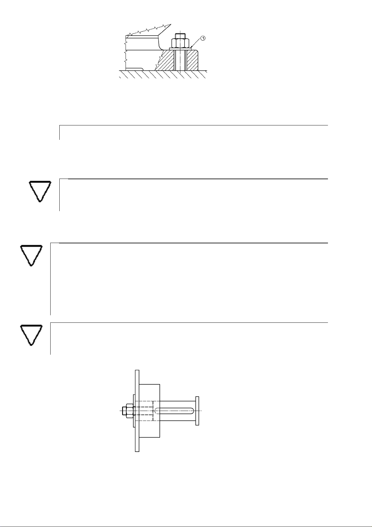
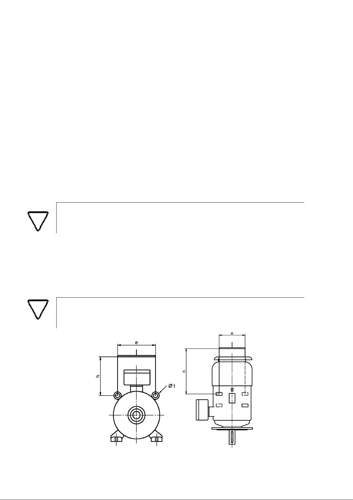
Figure 3: Motor Fastening
Large-surface Washer
In order to achieve an adequately large contact surface, apply a large-surface washer under each nut or screw head
.
>
Alternatively use flange nuts or bolts.
If the motors' shaft end points up or down (vertical mounting arrangement), it is necessary to fit an appropriate cover
to prevent any foreign bodies from dropping in the driven machine through the air inlet and outlet openings in the
ventilator hood.
Please note!
The flow of cooling air through the motor must not be limited by said cover.
The balance of the motors is specified on the shaft end plate and/or on the rating plate (H = half key, F = full key, N
= no key).
The design of the coupling or pulley must match the motor's balance.
Please note!
If balancing with half key (H), work on the vertical (visible) key components on the shaft diameter
or cover these with washers with keyway along the relevant length.
If the coupling is longer than the key, it is necessary to fill the keyway in the remaining part of the
coupling.
In case of failure to comply with the foregoing, out-of-balances liable of causing excessive vibrations may occur.
Please note!
Mount the pulleys or couplings only through the threaded bores in the shaft end to avoid damaging the anti-friction bearings.
Fig. 4: Fastening of the pulley or coupling
>
Screw the threaded bolts in the threaded bore.

>
Then mount the pulley or coupling on the shaft end: make sure to screw a nut with a washer having at least the
same diameter of the pulley hub or coupling on the threaded bolt.
Use the utmost care in mounting dynamically balanced pulleys or couplings on the shaft end. Machines to be connected to the motor by means of couplings are to be aligned according to the specifications of the coupling's manu
facturer.
Use only flexible couplings!
Mains and other electrical connections
The motors work as per VDE 0530 with mains voltage oscillations of up to ±10 % or frequency oscillations of up to –
5 % to +3 %. The mains ratings must match the voltage and frequency data specified on the ratings plate.
Connect the motors according to the connection diagrams attached to the terminal box. Use only the supplied original connection components.
Please note!
Carry out the motor, controller, overload protection and earthing connection operations in
compliance with local installation requirements.
Please note!
If the accidental starting of the system may expose the personnel to danger, do not use
any automatically restarting motor protective equipment.
Mains connection of explosion-protected motors
Besides any general installation regulations, follow carefully EN 60079-14 and EN 50281-1-2. Afterwards suitable
overload protection is to be provided either with a motor circuit breaker or similar protective devices. These may
include also PTC thermistors with tripping devices. These must be specified on the rating plate together with a tripping time t
.
A
In addition, any "Special Requirements" specified in the test certificate are to be complied with. These are marked
with an "X" after the test certificate number on the rating plate.
Motors with direct line lead-in
The free end of the cable inserted in the motor must be connected according to the regulations in force concerning
the connection area. If the line lead-in used on the motor is provided with pull relief, the cable can be laid freely; otherwise the cable must be secured with a pull relief device in the near vicinity.
The maximum operating temperature at the line lead-in must not
exceed 90° C.
Terminal box
Open the box by loosening the screws on the cover (Fig. 5) or, in the case of models with grub screw (Fig. 6), by
turning the grub screw counter-clockwise and then loosening the tapped cover.
Close the terminal box again after connecting the mains by following the same instructions in the opposite order.
In order to change the position of the cable and line lead-ins, you can turn the terminal box by 4
>
Loosen either
x
90°.
– the four fastening screws or
– the anti-rotation pins by means of the grub screw.
>
Turn the terminal box to the desired position.
-

Figure 5: Terminal box with fastening screw
Figure 6: Terminal box with grub screw
>
Then tighten the fastening components to the relevant torque, see the following table.
Table 4: Torque values for 8.8-type screws
Thread size
M5 6 Nm
M6 10 Nm
M8 25 Nm
M10 49 Nm
M12 85 Nm
M16 210 Nm
M20 425 Nm
Please note!
Terminal boxes fastened as per Fig. 6 are to be turned counter-clockwise by a maximum of
one turn away from the thread end stop. Screwed-on covers must be duly secured.
Anti-corrosion protection can be achieved with non-hardening sealing materials or sealing grease in particular on the
processed sealing surfaces of the covers of terminal boxes having the following degree of protection: "pressureresistant encapsulation, EEx d IIC(B) marking".
The approved sealing materials are:
• For threads and surfaces: Hylomar, by Marston-Domsel or
• for surfaces: Admosit and Fluid-D, by Teroson.
Please note!
In the case of "increased safety" terminal boxes the gaskets used are included in the
approval. Only original gaskets are to be used.
Please note!
"Pressure-resistant encapsulation“ terminal boxes must be sealed by means of approved cable or line lead-ins.
Torque

Cable and line lead-ins
Connect the motors with cable and line lead-ins or by means of a duct system as per EN 60079-14. These must
meet the following requirements:
• EN 50019 for wiring spaces with a degree of protection of "increased safety", (EEx e II marking on the component)
• EN 50018 for a degree of protection of "pressure-resistant encapsulation”, (component EEx d IIC(B) marking on
the component)
Specific test certificates must be provided for cable and line lead-ins.
Please note!
In case of motors complying with the new Directive 94/9/EC, (e.g. marking II 2G ...),
these must be mounted only with the supplied original lead-ins or lead-ins that meet
the requirements of the new directive.
Any openings that are not used must be closed with sealing plugs for which the relevant test certificates and/or the
aforementioned markings must be provided.
The supplied sealing plugs for the line lead-ins serve only as protection during transportation and are not an approved sealing means. This applies also for the storage of motors outdoors. In this case additional rain protection is
required.
The lead-ins supplied as a standard (version 1) are used for the insertion of firmly secured lines.
Version 3 available as a special accessory, with additional pull relief, is used for the insertion of lines in movable
motors.
Please note!
Cable lead-ins and sealing plugs that fail to meet these requirements are prohibited. The
cable and line diameters used must comply with the clamping range specified on the
lead-in.
Follow carefully the operating instructions of the cable and line lead-ins.
Motors with terminal boxes whose mains lead is located in the layer separating the upper and lower parts
Use only the supplied original gaskets to ensure compliance with the “Ex e II” degree of protection. Depending on
the type (see marking on the plug), the plugs are fit for the following diameters.
Follow carefully the operating instructions for the lead-in parts and sealing plugs.
Table 5: Cable diameter
>
After connecting the mains lead close the terminal box with the upper part.
>
Strip the skins of the plugs so that the following condition is fulfilled:
Type
RS-75 26 to 48 mm
RS-100 48 to 70 mm
Cable diameter
By stripping the skin, the plugs are adapted to the cable diameter so that a gap of less than 1 mm is obtained
between the cable and the plug applied on the cable.
Therefore, an extra layer of skin must be removed from one half of the module compared to other.
>
Lubricate the cutting edge and the sealing surfaces of the plug with the supplied grease.
>
Insert the plug halves over the cable and completely in the bushing opening.
>
Brace it with the screws until a perceivable resistance (maximum torque: 6 Nm) is achieved.

Figure 7: Cable lead-in
Maximum two line lead-ins, Roxtec, Rox RS Type plugs
Mains and guard circuit connection
The mains can be connected either with or without cable lug both in models with terminal board and in those with
single-conductor bushings.
Connect the power line to the relevant terminals as per the supplied wiring diagram.
Figure 8: Line connection
Connection without cable lug
Clamp
Connection with cable lug
Single-wire conductor without cable lug
>
When connecting a single-wire conductor without cable lug to terminals with just one screw, bend the conductor end as illustrated
.
Figure 9: Conductor bushing
Connection without cable lug
Connection with two cable lugs
Connection with one cable lug
Take note of the maximum connectable conductor cross-section for the terminals. If no other data is available on the

terminals, refer to the following table.
Table 6: Rated cross-sections
Shaft height
Rated cross-section [mm
63 to 112 4
132 to 160 10 (r)
180 to 225 70
250 to 280 120
315 150/ 300 (depending on the model)
over 355 300
2
]
In the case of "increased safety" terminal boxes, make sure to comply with the clearances specified in EN 50019
between conductive parts having different potentials. Tighten the screws and nuts on the live parts to the specified
torque.
Table 7: Clearances
Rated voltage, U [V]
Minimum clearance [mm]
175 < U ≤ 275 5
275 < U ≤ 420 6
420 < U ≤ 550 8
550 < U ≤ 750 10
750 < U ≤ 1100 14
2200 < U ≤ 3300 36
5500 < U ≤ 6600 60
8300 < U ≤ 11000 100
Table 8: Torques and current intensities for live pins
Thread size Torque [Nm]
Permissible continuous current
[A]
Brass Copper
M4 1.2 16 -
M5 2 25 -
M6 3 63 -
M8 6 100 -
M10 10 160 200
M12 15.5 250 315
M16 30 315 400
M20 52 400 630
Depending on the model, additional terminals for instance for temperature monitoring or space heater are located
either in the main terminal box or in additional terminal boxes; see the supplied wiring diagram.
Please note!
Take note of the rating data imprinted on the terminals.
Please note!
Keep the wiring diagram supplied in the terminal box in the enclosure with the documents belonging to the drive.
Motors with unidirectional fan
Make sure that the fan's direction of rotation matches that of the motor.
Motors with separate cooling via separately powered external fans
Make sure by means of the electric control that the main motor can be operated with the motor switched-on for separate cooling.

Motors with temperature monitoring
The motors are equipped with PTC's as per DIN 44081. Take note of the temperature data and tripping time
t
on
A
the rating plate.
Connect the PTC to an approved tripping device with marking PTB 3.53-PTC/A or
Please note!
The tripping device is not explosion-protected. For this reason install them outside the areas subject
to explosion hazards.
II(2) G.
The marking confirms whether the electrical data on the interface between the temperature sensor circuit and the
tripping device have been fulfilled. The use of the tripping device with PTC temperature sensors as per DIN 44081 is
allowed for the thermal monitoring of explosion-protected electrical machinery.
Being the only overload protection as set forth in EN 60079-14, the temperature sensors herein described can be
used together with an approved tripping device only if the tripping time
t
is specified on the motor rating plate. (Re-
A
fer to Section 3, Operation & Repairs, page 17)
Motors with space heater
The rating data for the space heater are specified either on the rating plate or on a separate plate. Depending on the
model, there are two heating variants:
• by means of heater bands powered via terminals HE1-HE2
• by means of the stator winding by feeding AC voltage to terminals U1-V1.
Please note!
Make sure by means of the electric control that the motor
voltage and the heater voltage are not fed simultaneously.
Please note!
The heater is not explosion-protected. It must not be switched
on at motor temperatures below -20°C to heat the motor to at
least –20°C. On the contrary, its purpose is that of preventing
that the motor temperature falls below –20°C when idle.
Motors for operating on frequency converters
For operating on frequency converters, motors with temperature monitoring must be protected by PTC temperature
sensors rating data for this operating mode are specified either on the rating plate or on a separate plate. If the relevant plate is missing, see the data provided in the manufacturer catalogue "Explosion-protected high and low voltage
AC motors in II 2 G EEx d(e) IIC(B) T4...T6“.
Check the drive's "electromagnetic compatibility" as per EMC directive no. 89/336/EEC when operating on frequency
converters.
Make sure when operating motors on frequency converters with a DC intermediate circuit that the admissible voltage
peak value of 1160 V is not exceeded by the periodically occurring commutation voltage peaks (threshold value for
terminals, clearances and creep distances).
If pulse width-modulated voltage source converters (pulse converter) are used for feeding power to the motors,
make sure that no high-frequency transients with high voltage peak values are generated. These may be generated
by the sharp switching edges of the voltage pulse especially along longer supply lines between the converter and
motor and shorten the life of the winding insulation. The normal design of the terminals and bushings for 750 V is
suitable for peak voltages of 1200 V. Higher voltage peaks require the application of bushings and terminals for
1100 V. The approved value for the periodic peak voltage amounts to 1600 V. If the periodic voltage peaks exceed
1600 V, high-voltage insulation systems must be applied.
In the case of a converter output non-galvanically separated from the mains and with current limitation, follow the
requirements of DIN EN 50178 and VDE 0160 (equipment of high voltage installations with electronic devices) on
the overload protection of the protective earth conductor.
In rating the protective device in the outer conductors, bear in mind that the protective earth conductor current can
be greater than the outer conductor current in fault condition. The protective earth conductor is to be dimensioned
according to this fault current.

Take note of all of the data of the converter manufacturer for said fault condition.
Motors with brake
The mains line in the version with incorporated brake is connected in the motor terminal box and in the version with
the built-on brake in the separate brake terminal box. Observe the supplied connection diagram and the rated voltage visible on the rating plate. In the presence of an AC connection the brake coil is energized by means of a silicon
rectifier accommodated inside the explosion-proof encapsulation.
>
The temperature sensors applied both in the motor and brake are to be connected as envisaged in
Section "Motors with temperature monitoring", page 13.
Motors with brake or tachometer mounted under the ventilator hood
In order to connect brakes or tachometers mounted under the motor ventilator hood, the latter must be disassembled.
Unscrew any shock pulse sensors or regreasing devices. Loosen the fastening screws on the hood and remove the
hood from the motor.
Connect the brake of tachometer as per the attached circuit diagram and pass the cable along the shortest route
through the motor fins towards the main terminal box. It is recommended to insert a protective tube over the connection cable in the fin area to prevent wearing.
Fit the ventilator hood back on the motor and check the position of the boreholes for any shock pulse sensors and
regreasing devices. In the case of motors with an axial fan running into a nozzle, make sure that there is a uniform
air gap all around between the fan and nozzle. Secure the hood with the fastening hoods.
Check manually that the fan runs freely once the mounting is completely.
Motors with backstop
Motors with built-in backstop must be operated at a minimum rpm higher than the value specified on the rating plate
– e.g. FXM 850 min
–1
– to prevent excessively high temperatures.

Connection diagrams
The circuit diagram on the motor is to be followed.
Single-speed – one pole
∆
circuit
Y circuit
Pole changing
Low rpm High rpm
Dahlander connection
Low rpm High rpm
Dahlander connection
ow rpm High rpm L
1TP11TP2
Pre-alarm PTC U>2.5V not allowed Use tripping device with
PTB number or
marking II (2)G
2TP12TP2
1R1-R2 PT 100 resistance temperature sensor
Tripping PTC
HE1-
Space heater
HE2

Brakemotors with incorporated brake
Brake connection via motor winding
Y circuit
Terminals 1-2 can be connected directly to the
motor terminals to supply the brake. Compare
the motor/brake voltages to determine whether
the connection is to be made on U1-U2 or U1V1.
Terminals 3-4 must be bridged.
Y circuit
Brake
An external power supply can be applied on
terminals 1-2. Check the voltage data on the
rating plate. Terminals 3-4 must be bridged.
For a rapid engagement of the brake (DCvoltage side tripping) bridge 3-4 can be replaced by a contact. The contact must be
tripped simultaneously with the brake power
supply.
∆ circuit
BA1-BA4
1TP1-1TP2
2TP1-2TP2
HE1-HE2
TB1-TB2
In order to provide for the emergency venting
of the brake, e.g. to turn the motor manually,
you can apply a DC voltage source to terminal
1-4 (remove any other wiring before hand and
observe the polarity).
U voltage = = U~ x 0.45
U voltage~see brake voltage on the rating
plate.
Brake
Pre-alarm PTC
Tripping PTC
Space heater
Temperature monitoring: Microtherm T 10
U>2.5V not allowed Use tripping device
with PTB number or
marking II(2)G

y
Brake connection via external power supply
Y circuit ∆ circuit Brake connection
Pole changing
Low rpm High rpm
circuit Y circuit
Y
Pole changing Dahlander connection
Low rpm
∆ circuit
High rpm
circuit
Y Y
1-4 Brake
10-11 Tripping PTC Pre-alarm PTC Use tripping device with PTB number
12-13 Tripping PTC
70-71 Space heater
P1-P2 Temperature monitoring: Microtherm T 10
Brake power
supply via
terminals 1-2.
Observe the
voltage data
on the rating
plate. Terminal 3-4 must
For a rapid
engagement
of the brake
(DC-voltage
side tripping)
bridge 3-4
can be replaced by a
contact. The
contact must
be tripped
simultaneousl
with
3 Operation and Repairs
Duty types and thermal protection
• In S1 duty class motors a temperature sensor (TS) can be used in addition to the motor circuit breaker as required
by DIN EN 60079-14, VDE 0165.
• If in S1 duty cycle motors protection is to be provided against overheating only by means of the TS, a proven combination of TS and tripping device is to be used for said purpose.
• In the case of non-S1 duty cycle motors proven combinations of TS and tripping device must be used as protection
against overheating.
• The supplying of power to the motors via the frequency converter is permissible only if a proven combination of TS
on the windings and tripping device is used.
Special operating conditions
The operating of the motors at ambient temperatures outside the generally valid range of –20 to +40 °C is allowed also
without heater if an appropriate temperature range – e.g. –55 °C < T
Operation at less than –20°C is allowed also without any additional indication if the temperature of the entire motor is
maintained at least at -20 °C by means of a space heater.
At motor temperatures of less than -20°C the heater must not be started, as these are not explosion-protected.
Heat input through the driven machine
It must be ensured that no quantities of heat greater than the maximum heating values specified in table are conveyed
from a mounted machine to the interface with the motor (e.g. shaft and motor flange). This way it is guaranteed that no
point of the motor exceeds the temperature class.
Table 9: Permissible surface heating at an ambient temperature of 40°C:
< 60 °C – is specified on the rating plate.
amb

Item
T6 = 85°C T5 = 100°C T4 =135°C
1. Permissible heating on the shaft 30K 45K 65K
2. Permissible heating on the flange 30K 45K 65K
Temperature class
Start-up
Please note!
Before mounting or start-up the insulation resistance is to be measured by qualified technicians.
The resistance must be greater than 1 MΩ. A critical value is reached at 0.5 MΩ. If this value is not
reached, the motors must be dried.
The best way to do it is in an oven at temperatures up to 100 °C. To eliminate any humidity, open the motor. To be
entitled to any warranty claims, contact the manufacturer in advance.
These works must be carried out by qualified technicians; in the course of said works the manufacturer shall instruct
said technicians on how to ensure the explosion protection during reassembly. For the assembly and disassembly, see
the relevant repair instructions.
• Check the direction of rotation and operation during idle running. In case of unidirectional external fans (axial fans)
observe the sign for the direction of rotation on the motor. If the direction of rotation needs to be changed, invert the
two power lines and the fan.
• If the motor was stored and an additional quantity of grease was applied in the anti-friction bearings, the motor must
be run with no load for at least 0.5 h to ensure an adequate distribution of the grease and to avoid the overheating of
the anti-friction bearings.
• Make sure that the operating current matches the specified current values on the rating plate.
The protective equipment required as per EN 60079-14 is to be set according to the motor rating values specified on
the rating plate. The specified current value on the rating plate must not be exceeded in continuous duty conditions.
Please note!
Run the motor with load for at least 1 hour and check that there is no unusual noise or heating exceeding the specified temperature class values.
Relubricate motors with regreasing equipment with the specified amount of grease during start-up.
Vibration severity values of V
< 3.5 mm/s (
eff
P
<15 kW) or 4.5 mm/s (
N
P
> 15 kW) in coupled operating mode are
N
not allowed. In case of deviations from normal operating conditions – e.g. higher temperatures or greater noise and
vibrations – find the cause and, if necessary,
contact Producent.
Please note!
The protective equipment must always be kept in service also during trial runs. In case of doubt
switch off the machine.
Maintenance
Inspection
• The motors are to be constantly monitored depending on the operating conditions.
• Keep the motors clean and the venting openings free
Any national regulations valid for the maintenance/repair of electrical equipment in areas subject to explosion hazards e.g. in Germany the Operational Safety Order, etc - are to be complied with.
During maintenance especially those parts on which the degree of protection depends must be checked; these include,
for instance, the integrity of the lead-in components and gaskets.

Lubrication
Please note!
In order to avoid damage the bearings and grease must be kept clean.
The deep groove ball bearings of motors up to frame size 280 are sealed on both sides and filled by the bearing manufacturer with a grease which is enough for normal operating conditions in 4 or multi-pole motors for 40000 operating
hours or in 2-pole motors for 20000 operating hours.
When changing the bearings, change also the shaft seals. To do so, dismount the motor so that the winding can be
cleaned at the same time. Disassembly and assembly as per the specific manufacturer repair instructions.
Motors starting from frame size 315 and motors with reinforced bearings are to be equipped with regreasing devices.
The bearings are to be regreased preferably with the motor running with a grease gun through the grease nipples located over the bearing plates or bearing caps.
The drip space in the bearing cap for outflowing old grease is large enough to collect the outflowing grease during the
nominal bearing service life with state-of-the art regreasing.
See the plate on the motor for the specified lubricating intervals and the type and quantity of grease to be used. The
manufacturer normally uses ESSO Unirex N3, a lithium complex soap/mineral oil grease.
Table 10: Standard regreasing intervals in hours
Ambient
temperature
Rpm up
to 1800 min
–1
Rpm up
to 3600 min
–1
40 °C 5000 h 2500 h
50 °C 2500 h 1000 h
Please note!
In motors with enhanced performance (motor type ...X), in heavy drive conditions like belt and gear
drive with additional bearing loads and in vertical designs the lubricating intervals are to be reduced
by 50%.
Observe the specified quantity of grease. Overgreasing can lead to a sharp increase in the bearing
temperature and hence to the failure of the bearing.
Caution!
If regreasing is carried out while the motor is running, provide for adequate protection against rotating parts!
Only resin-free and acid-free anti-friction bearing grease with a drop point of approx. 200°C is to be
used.
Explosion protection
The marking
(II2G), EEx de IIC T4, for instance, indicates where the motor is to be used and that it has been designed, built and approved according to the relevant European standards required for operation in areas subject to
explosion hazards.
Please note!
The motor must not be altered in any way whatsoever and the operating instructions set forth
herein are to be complied with always.
If the motor is altered or repairs need to be made, these are to be performed by the manufacturer or by repair workshops or factories that possess the necessary know-how. Before the starting the motors again, conformity with the
requirements of EC directives 76/ 117/EEC or 94/9/EC and 99/92/EC by said sites is to be ascertained and confirmed
by means of an appropriate marking on the motor or by issuing a test report.
If these requirements are not met, the motor is no longer classified as explosion-protected and the marking - see
above - is to be removed.

Instructions for ensuring explosion protection during operation
• All of the contact screws and nuts of the electrical connections are to be tightened securely to prevent excessively
high contact resistance values that may lead to an excessive degree of overheating of the contact point; torque
values.
• Use the utmost caution when connecting the mains cable. Observe the creep distances and clearances. Use duly
the sealing parts of the cable lead-ins and connections spaces as well as the lead-in parts envisaged for the pull
relief or as protection against torsion in order to maintain the degree of protection of the connection spaces.
• Eliminate any damages immediately and use only original spare parts. The proper performance of the works by the
aforementioned sites is to be examined as per the relevant EC directives, in Germany by a qualified expert as per
ElexV, abroad as per the relevant national regulations in force and to be confirmed by means of an appropriate
marking on the motor or by issuing a test report.
• The surfaces of ignition-protected gaps must not be reworked. Keep these surfaces metallically clean. Corrosion
protection can be achieved by means of non-hardening sealing materials or sealing grease. The approved sealing
materials include besides the corrosion protection greases available on the market: Hylomar, by Marston-Domsel
or Admosit and Fluid-D, by Teroson (follow the manufacturer's usage instructions). This must be observed in par-
ticular for the openings in the cover for connection spaces having a pressure-resistant encapsulation degree of
protection, marking EEx d IIC(B).
•
All the screws are to be tightened to the envisaged torque and just as many screws as necessary for the envisaged
fastening boreholes are provided. Any damaged screws are to be replaced only with screws of the same dimensions and quality.
Repairs
Repairs and changes to explosion-protected machines are to be carried out by one of the aforementioned sites as
per EC directives 94/9/EC and 99/92/EC, in Germany in compliance with the Operational Safety Order as well as
with the safety regulations and requirements of the repair instructions.
Any works relating to the explosion protection must be carried out by the manufacturer or by a specialized workshop
for electrical machinery. If said works are not performed by the manufacturer, these must be surveyed by an authorized qualified person.
In Germany a written certificate as per the Operational Safety Order is required for restarting. In foreign countries the
national regulations in force are to be complied with.
3 Additional dust protection requirements
(application in zones 21 and 22)
Intended use
A marking of at least IP 65 and
Installation and Operation
Cable and line lead-ins
Separately approved lead-ins belonging to category 2G with at least IP 65 or category are to be used. Any openings
that are not used are to be closed with duly approved plugs.
Operation and Repairs
The motors must not be operated with excessive dust deposits, as these may lead to the exceeding of the admissible surface temperature. Regular cleaning must be performed.
The radial shaft seal rings are included in the approval. Only original gaskets are to be used.
II 2D T …° C must be found on the motor's rating plate.


 Loading...