

Velvac Road-iQ Installation Manual

Road-iQ VideoData Server
Installation Manual

INSTALLATION MANUAL
Road-iQ VideoData Server
ABOUT THIS MANUAL
The purpose of this Installation Manual is to give you an in depth understanding and installation process of your new
Road-iQ system. It also includes an overview of product specifications information pertaining to the tablet interface.
For more guides or for additional information please visit www.road-iq.solutions/GettingStarted.
© 2016 Velvac Inc. All rights reserved.
Road-iQ Version: 1.0 Published: Februrary 2016
Road-iQ is a registered trademark of Velvac Inc.
Information in this user guide is subject to change without prior notice.
Part Number: X3683
Revised 2/27/2015 P a g e | 2

INSTALLATION MANUAL
Road-iQ VideoData Server
SAFETY NOTES
The DVD video display of the in-dash unit will not operate while the vehicle is moving. This is a safety feature to prevent
driver distraction. Tablet control functions will only operate when vehicle is in Park and the parking brake is engaged. It
is illegal in most states for the driver to view video while the vehicle is in motion.
This device complies with Part 15 of the FCC Rules. Operation is subject to the following two conditions:
(1) This device may not cause harmful interference, and
(2) This device must accept any interference received, including interference that may cause undesired operation.
Ce dispositif est conforme aux Normes établies par la FCC (Partie 15). Cette opération est soumise à deux conditions:
(1) Ce dispositif ne peut causer d’interférences nuisibles.
(2) Ce dispositif doit accepter toutes interférences reçues, même si elles provoquent un dysfonctionnement du
dispositif.
This product complies with Industry Canada RSS-210.
This device complies with Industry Canada license-exempt RSS standard(s). Operation is subject to the following two
conditions:
(1) This device may not cause interference, and
(2) This device must accept any interference, including interference that may cause undesired operation of the device.
Under Industry Canada regulations, the radio transmitter(s) in this device may only operate using an antenna of a type
and maximum (or lesser) gain approved for the transmitter by Industry Canada. To reduce potential radio interference
to other users, the antenna type and its gain should be so chosen that the equivalent isotropically radiated power
(e.i.r.p.) is not more than that necessary for successful communication.
Cet appareil est conforme aux norme RSS210 d’Industrie Canada.
Cet appareil est conforme aux normes d’exemption de licence RSS d’Industry Canada. Son fonctionnement est soumis
aux deux conditions suivantes :
(1) cet appareil ne doit pas causer d’interférence et
(2) cet appareil doit accepter toute interférence, notamment les interférences qui peuvent affecter son fonctionnement.
Conformément aux réglementations d'Industry Canada, les émetteurs radio de cet appareil ne peuvent fonctionner qu’à
l’aide d'une antenne dont le type et le gain maximal (ou minimal) pour ces émetteurs - transmetteurs sont approuvés
par Industry Canada. Pour réduire le risque d’interférence éventuelle pour les autres utilisateurs, le type et le gain de
l’antenne doivent être choisis de manière à ce que la puissance isotrope rayonnée équivalente (p.i.r.e.) minimale
nécessaire à une bonne communication soit fournie.
Part Number: X3683
Revised 2/27/2015 P a g e | 3

INSTALLATION MANUAL
Road-iQ VideoData Server
Information to the User
This equipment has been tested and found to comply with the limits for a Class B digital device pursuant to Part 15 of
the FCC Rules.
These limits are designed to provide reasonable protection against harmful Interference in a residential installation. This
equipment generates, uses, and can radiate radio frequency energy and, if not installed and used in accordance with the
instructions, may cause harmful Interference to radio communications. However, there is no guarantee that
interference will not occur in a particular installation.
RF Radiation Exposure Statement
This equipment complies with the FCC/IC radiation exposure limits set forth for portable transmitting device operation
in an uncontrolled environment. End users must follow the specific operating instructions to satisfy RF exposure
compliance.
The equipment should only be used or installed at locations where there is normally at least a 20cm separation between
the antenna and all persons.
This transmitter must not be co-located or operated in conjunction with any other antenna or transmitter.
Any changes or modifications not expressly approved by the party responsible for compliance could void the user’s
authority to operate this equipment.
Part Number: X3683
Revised 2/27/2015 P a g e | 4

INSTALLATION MANUAL
Road-iQ VideoData Server
The Road-iQ VideoData Server is a video and data display, acquisition, and playback system. The Road-iQ
VideoData Server is designed to collect and record video data from up to six (6) cameras installed on your vehicle, as
well as system parameters from your vehicle-bus communication network and GPS location, all in-sync. Live video can
be displayed on an iPad on the vehicle’s dash in real-time, and recorded video and data can be reviewed on the tablet or
transferred to a personal computer. Further, the Road-iQ VideoData Server allows the definition of triggers, which use
vehicle parameters to define significant events (excessive speed, panic braking, etc…) which are then marked in the
recorded files for easy locating.
Contents
1 System Contents & Requirements .................................................................................................................................. 9
1.1 System Contents ..................................................................................................................................................... 9
1.2 Vehicle, Hardware & Software Requirements ...................................................................................................... 10
2 Installation .................................................................................................................................................................... 11
2.1 System Diagram .................................................................................................................................................... 11
2.2 VideoData Server Front Panel ............................................................................................................................... 14
2.3 NetHub Ports ......................................................................................................................................................... 14
Part Number: X3683
Revised 2/27/2015 P a g e | 5

INSTALLATION MANUAL
Road-iQ VideoData Server
2.4 Required Tools & Equipment ................................................................................................................................ 15
2.5 Warnings ............................................................................................................................................................... 15
2.6 Planning Your Installation ..................................................................................................................................... 15
2.7 Mounting the iPad ................................................................................................................................................ 17
2.7.1 Rosen Mount ................................................................................................................................................. 17
2.7.2 RAM Mount ................................................................................................................................................... 17
2.7.3 Padholdr ........................................................................................................................................................ 17
2.8 Mounting the VideoData Server & NetHub .......................................................................................................... 17
2.9 Powering the Road-iQ VideoData Server .............................................................................................................. 17
2.10 Connecting to the vehicle CAN-bus ...................................................................................................................... 18
2.11 Connecting the NetHub ........................................................................................................................................ 19
2.12 Connecting the GPIO Harness ............................................................................................................................... 20
2.13 Connecting the camera(s) ..................................................................................................................................... 21
2.14 Installing the GPS antenna ....................................................................................... Error! Bookmark not defined.
3 Setup ............................................................................................................................................................................. 22
3.1 Accessing the Installer Control Panel .................................................................................................................... 22
3.2 Control Panel ‘Status’ Screen ................................................................................................................................ 23
3.3 Video Setup ........................................................................................................................................................... 24
3.4 Cellular Service Setup ............................................................................................................................................ 29
3.5 Wi-Fi Setup ............................................................................................................................................................ 29
3.6 Hotspot Info & Setup ............................................................................................................................................ 31
3.7 Sensors Info & Setup ............................................................................................................................................. 33
3.8 Storage Setup ........................................................................................................................................................ 34
3.9 Users Setup ........................................................................................................................................................... 34
3.10 System Updates .................................................................................................................................................... 35
3.11 Installing the Road-iQ app ..................................................................................................................................... 36
3.12 Connecting the iPad and the Road-iQ VideoData Server ...................................................................................... 36
3.13 App Setup .............................................................................................................................................................. 37
3.14 Verify Operation .................................................................................................................................................... 37
4 Operation ...................................................................................................................................................................... 38
4.1 Getting Started ...................................................................................................................................................... 38
4.2 Home Screen ......................................................................................................................................................... 39
Part Number: X3683
Revised 2/27/2015 P a g e | 6

INSTALLATION MANUAL
Road-iQ VideoData Server
4.3 Pre-Drive Check ..................................................................................................................................................... 41
4.4 Drive-Mode ........................................................................................................................................................... 41
4.4.1 Live Streaming Video..................................................................................................................................... 42
4.4.2 Gauges ........................................................................................................................................................... 42
4.4.3 Summary ....................................................................................................................................................... 43
4.4.4 Snapshots ...................................................................................................................................................... 43
4.4.5 Map ............................................................................................................................................................... 44
4.5 Vehicle Security ..................................................................................................................................................... 44
4.5.1 Remote Access & Control .............................................................................................................................. 44
4.5.2 Remote Video ................................................................................................................................................ 44
4.6 Comfort Controls ................................................................................................................................................... 45
4.6.1 Lighting .......................................................................................................................................................... 45
4.6.2 Temperature ................................................................................................................................................. 45
4.6.3 Cameras......................................................................................................................................................... 46
4.7 Settings .................................................................................................................................................................. 46
4.7.1 Display Settings ............................................................................................................................................. 47
4.7.2 Navigation Settings ....................................................................................................................................... 47
4.7.3 Software Updates.......................................................................................................................................... 47
4.7.4 Wi-Fi Settings & Password ............................................................................................................................ 47
4.8 Playback ................................................................................................................................................................ 47
4.9 Library ................................................................................................................................................................... 48
4.9.1 Owner’s Manual ............................................................................................................................................ 48
4.9.2 Technical Documentation ............................................................................................................................. 48
4.10 Vehicle Setup ........................................................................................................................................................ 48
4.10.1 Vehicle Leveling ............................................................................................................................................. 48
4.10.2 Slides ............................................................................................................................................................. 49
4.10.3 Awnings ......................................................................................................................................................... 49
4.11 Viewing Recorded Video; recorded video storage location. ................................................................................ 49
4.12 Exporting Video ..................................................................................................................................................... 50
4.13 Deleting Video in the ROAD-IQ VIDEODATA SERVER App .................................................................................... 50
4.14 Clearing the iPad Photo Folder ............................................................................................................................. 50
4.15 Upgrading app software ....................................................................................................................................... 50
Part Number: X3683
Revised 2/27/2015 P a g e | 7

INSTALLATION MANUAL
Road-iQ VideoData Server
4.16 Upgrading ROAD-IQ VIDEODATA SERVER firmware ............................................................................................. 50
5 System specifications .................................................................................................................................................... 50
6 Troubleshooting ............................................................................................................................................................ 50
7 Glossary of Terms & Acronyms ..................................................................................................................................... 52
8 Appendix ....................................................................................................................................................................... 52
8.1 WIRING DIAGRAMS ............................................................................................................................................... 52
8.2 HARNESS DRAWINGS ............................................................................................................................................ 53
8.3 Control Panel Screens ........................................................................................................................................... 53
8.3.1 Status Screen ................................................................................................................................................. 53
8.3.2 Video ............................................................................................................................................................. 53
8.3.3 Wi-Fi .............................................................................................................................................................. 54
8.3.4 Hotspot .......................................................................................................................................................... 54
8.3.5 Sensors .......................................................................................................................................................... 55
Part Number: X3683
Revised 2/27/2015 P a g e | 8
INSTALLATION MANUAL
Road-iQ VideoData Server
1 SYSTEM CONTENTS & REQUIREMENTS
1.1 SYSTEM CONTENTS
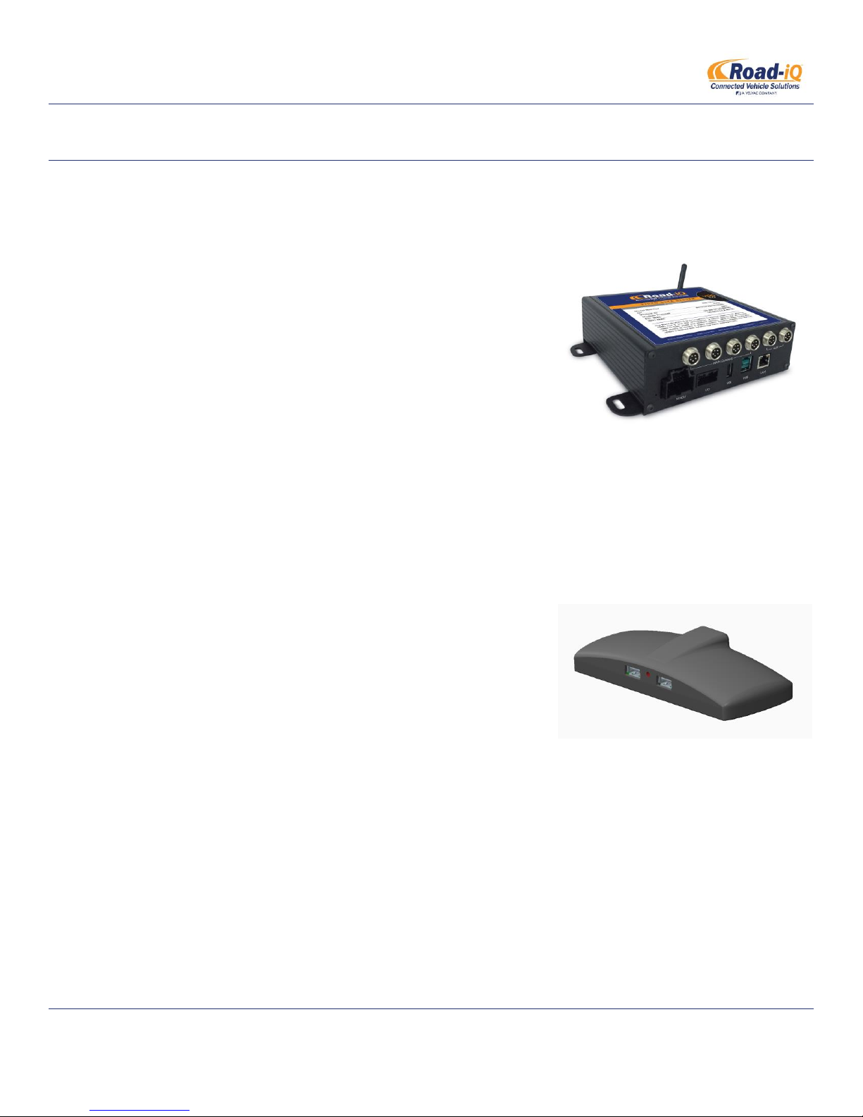
Road-iQ VideoData Server (standard equipment)
o Road-iQ VideoData Server
The Road-iQ VideoData Server is the main component of the
Road-iQ VideoData Server system. The server is responsible
for the collection and management of videos, GPS data, driver
inputs, and vehicle data for display, recording, and playback.
The Road-iQ VideoData Server can also act as a Wi-Fi Hotspot
by way of cellular service through the optional NetHub.
o Mounting Hardware
Four (4) ¼ inch self-tapping screws are included for mounting the Road-iQ VideoData Server to a
wooden or plastic surface.
Road-iQ NetHub (optional)
o NetHub
The optional NetHub mounts on the vehicle dash and acts as
an intermediary between the Road-iQ VideoData Server and
the iPad. There are two USB ports on the front of the NetHub
for connection to both the iPad and an external USB mass
storage device. The NetHub also contains the LTE modem,
GPS, antennas, an LED indicator, a warning buzzer, and a SIM
card slot.
o NetHub Cable
The NetHub cable is a 3-meter (approx. 10 feet) long Powered-USB 2.0 cable which connects the RoadiQ VideoData Server with the NetHub.
o Mounting Materials
Adhesive-backed mounting material is included for attaching the NetHub to the vehicle.
Vehicle Harness
The Vehicle Harness provides power and ground for the system, as well as the connection between the
Road-iQ VideoData Server and the vehicle-bus network(s). This connection provides the Road-iQ
Part Number: X3683
Revised 2/27/2015 P a g e | 9

INSTALLATION MANUAL
Road-iQ VideoData Server
VideoData Server with data from one or more of the supported vehicle vehicle-bus network protocols
(J1939, RV-C, OBDII CAN, J1708/J1587, LIN). There are various types of vehicle harnesses available based
on the type of installation.
GPIO Harness (optional)
o The Road-iQ VideoData Server supports four (4) general purpose inputs and four (4) general purpose
outputs. The inputs can be used as triggers from vehicle systems that aren’t on the vehicle-bus network.
The GPIO (general-purpose input/output) harness serves as the access points for the system’s general
purpose inputs and outputs, as well as secondary connections to the vehicle’s LIN-bus and accessory
signal input.
Velvac Proprietary USB Storage (optional)
User’s Manual
Quick Startup Guide
1.2 VEHICLE, HARDWARE & SOFTWARE REQUIREMENTS
Apple iPad Air, iPad Air 2, iPad Mini 2, or iPad Mini 3
o Apple iOS 8 or newer.
o Any iPad storage capacity may be used, though storage size will limit the amount of video and data that
can be stored.
For reading and storing vehicle data, a vehicle with one or more of the following supported communication
protocols is required:
o SAE J1939
o RV-C
o OBDII-CAN
o SAE J1708/J1587
o LIN
Data Storage – the Road-iQ VideoData Server system can store video and vehicle data in a number of different
user-selectable locations:
o On the iPad
o On a USB mass storage device plugged into the Road-iQ video server
o On a USB mass storage device plugged into the NetHub
A USB mass storage device must be a Flash or SSD drive, or an in-vehicle qualified hard-drive. In addition to
providing additional storage capacity, a USB mass storage device allows recording of video when the iPad is not
connected to the system, and is required to support remote video retrieval from the web.
Part Number: X3683
Revised 2/27/2015 P a g e | 10

INSTALLATION MANUAL
Road-iQ VideoData Server
The rule of thumb in determining how much storage capacity is required is X MB required per hour of recorded
vehicle data, and Y MB required per hour of recorded video channel. For example, a system with 4 video
channels, and recording vehicle data, will require (X+4Y) MB for every hour to be recorded. To retain 6 hours of
recorded video and vehicle data, 6(X+4Y) MB of free storage space will be required.
2 INSTALLATION
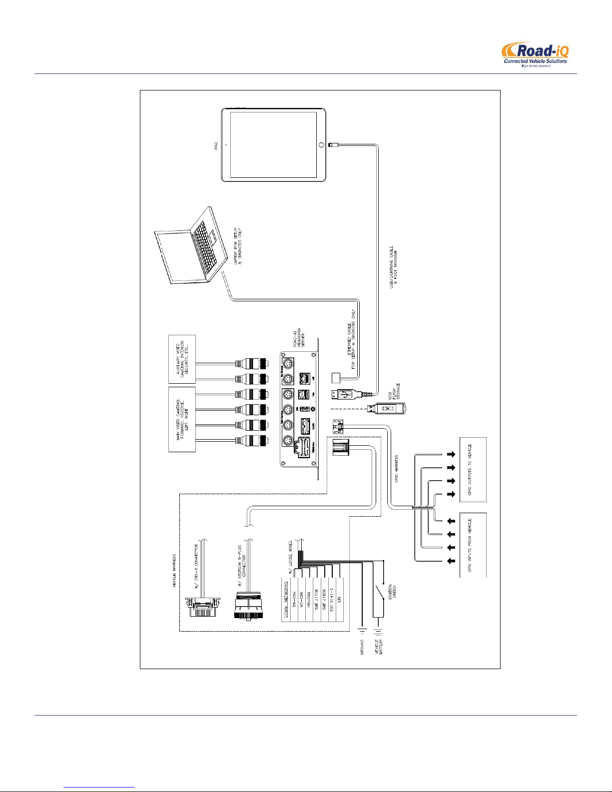
2.1 SYSTEM DIAGRAM
For a basic installation (without NetHub):
Part Number: X3683
Revised 2/27/2015 P a g e | 11
INSTALLATION MANUAL
Road-iQ VideoData Server
Part Number: X3683
Revised 2/27/2015 P a g e | 12
INSTALLATION MANUAL
Road-iQ VideoData Server
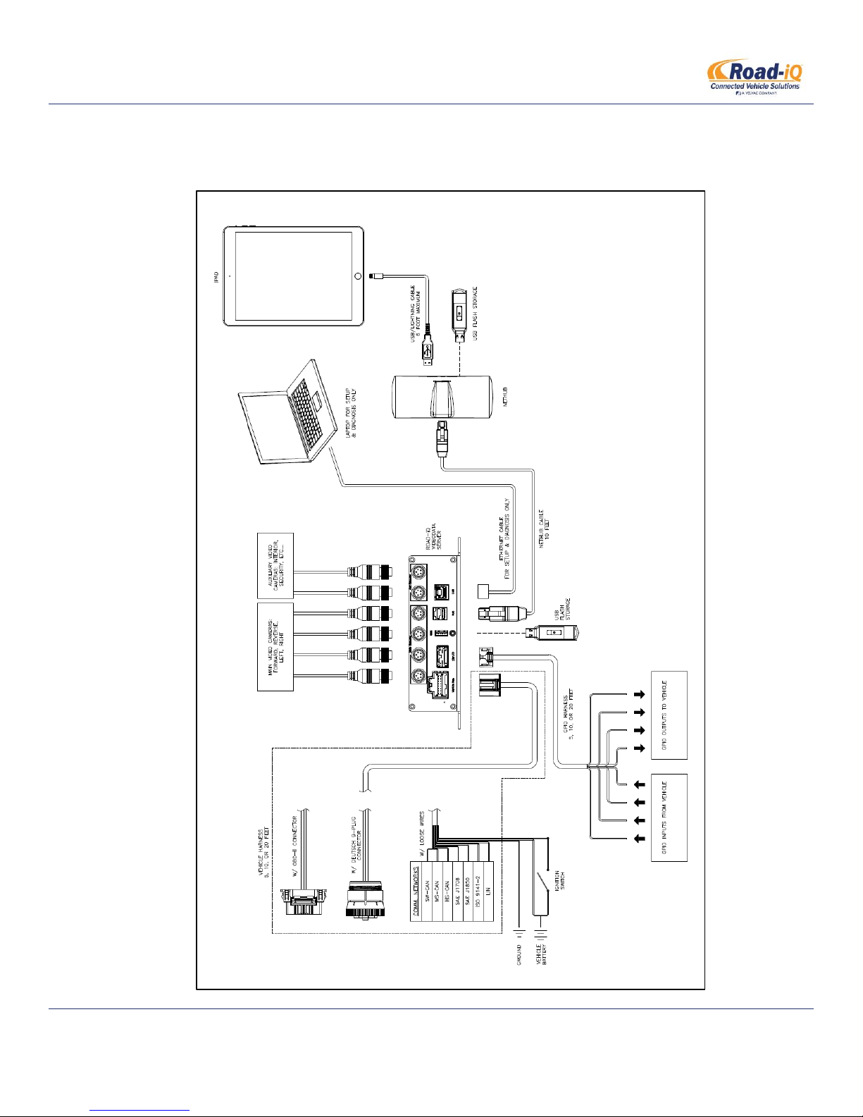
If installing a NetHub-equipped system, use the following diagram:
Part Number: X3683
Revised 2/27/2015 P a g e | 13
INSTALLATION MANUAL
1
2
3
4
5
6
7
2
1
3
4
Road-iQ VideoData Server
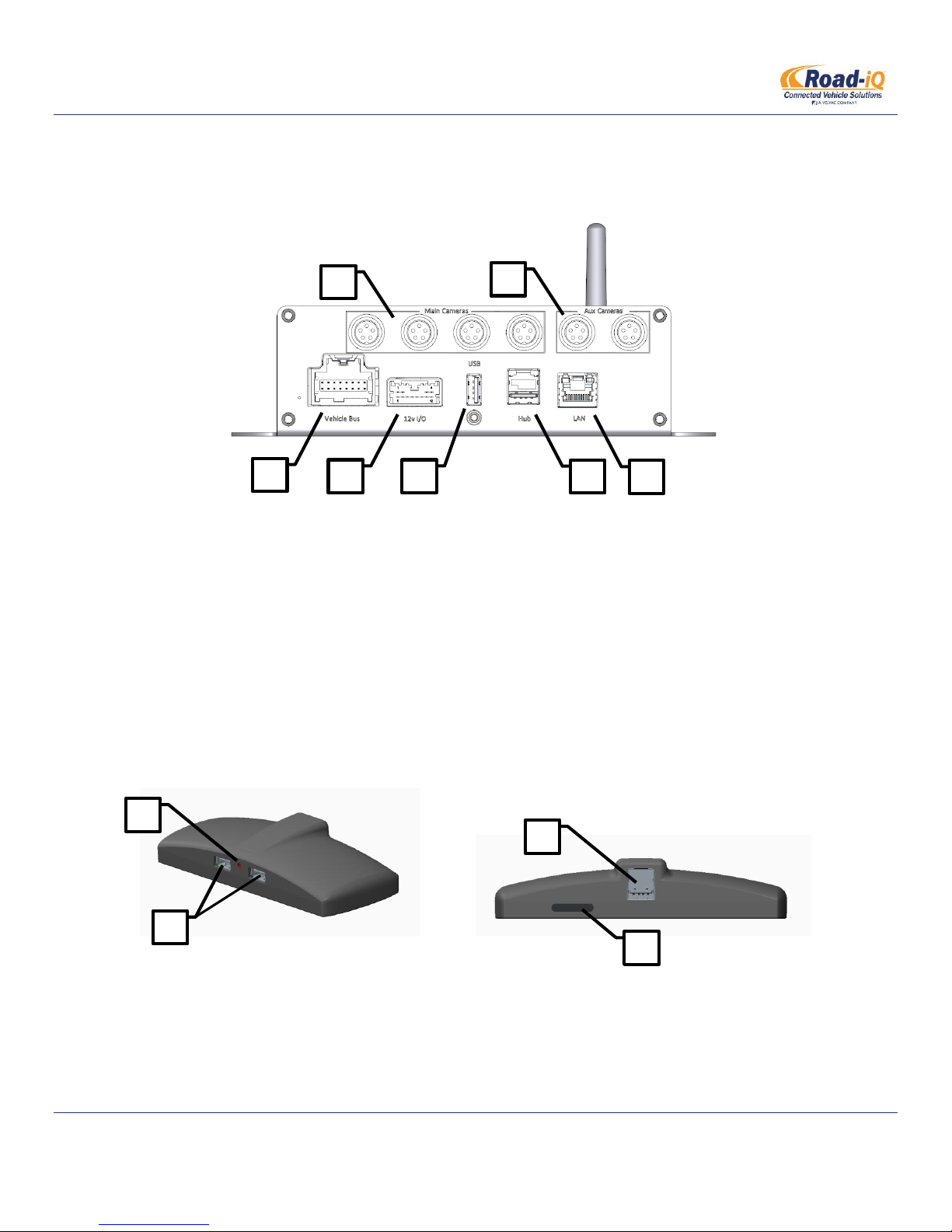
2.2 VIDEODATA SERVER FRONT PANEL
2.3 NETHUB PORTS
1. Main Camera Inputs
2. Auxiliary Camera Inputs
3. Vehicle Harness Connection
4. GPIO Harness Connection
5. USB Port
6. NetHub Connection
7. LAN Connection
1. LED Indicator
2. USB Ports
3. NetHub Cable Port
4. SIM Card Slot
Part Number: X3683
Revised 2/27/2015 P a g e | 14

INSTALLATION MANUAL
Road-iQ VideoData Server
2.4 REQUIRED TOOLS & EQUIPMENT
Safety Glasses
#2 Philips Head Screwdriver
Wire cutters
Wire strippers
Crimp connectors
Heat shrink tubing
Power drill
Drill bits (pilot holes for VDS mounting screws)
Hole saws, various sizes as required to route wiring harnesses
Rubber grommets, various sizes as required to route wiring harnesses
Multimeter
iPad or laptop with a web browser
o Wi-Fi capability or Ethernet port & cable required
2.5 WARNINGS
Always disconnect the vehicle battery when working on vehicle electrical systems
Always use safe practices when creating new wiring connections
2.6 PLANNING YOUR INSTALLATION
There are some considerations that should be planned for before mounting the components or routing the harnesses of
the Road-iQ Video Data Server. These considerations include:
Location of the iPad
o As the end user’s primary point of contact with the system, the location of the iPad should typically take
priority over the location of other system components.
o It is recommended that the Lightning cable that connects to the iPad be a maximum of 2.5-feet in
length, which will restrict the location of the other components in the system. This distance can be
extended through use of either the NetHub, or a high-quality USB extension cable.
o It is recommended that the iPad mounting location not obstruct the driver’s view of the road, yet it
should still be easily visible with a quick glance.
o The recommended mounting location of the iPad is below the overhead storage compartments,
centered left-to-right, which places the iPad where an automotive rear-view mirror would be located.
Location of the NetHub
o In addition to expanded system functionality, the optional NetHub also helps to extend the distance
between the Road-iQ VideoData Server and the iPad. The maximum 2.5-foot long Lightning cable now
plugs into the NetHub, which is connected to the Road-iQ VideoData Server by the NetHub cable (10
feet). See the diagrams in section 2.1 for more information on the connections between components.
o The NetHub cable length will partly determine the available mounting locations for the VideoData
server. Various lengths of NetHub cables are available if needed.
Part Number: X3683
Revised 2/27/2015 P a g e | 15

INSTALLATION MANUAL
Road-iQ VideoData Server
o The NetHub should mount with a line-of-sight to a vehicle window to ensure adequate GPS and cellular
reception.
o Recommended locations for the NetHub, in order from best-to-worst, are:
Underside of the overhead storage (behind the iPad)
Driver or passenger kick-panel areas (similar to a brake controller)
o Do not mount the NetHub in the following locations:
Inside any closed area (dash, glove-box, cabinet, etc…)
Close to high-power equipment (batteries, generator, etc…)
Location of the Road-iQ VideoData Server
o It is recommended that the Road-iQ VideoData Server, particularly the connections on the front panel,
remain accessible by the end user for maintenance purposes.
o The Road-iQ VideoData Server should be mounted on a flat and rigid surface. For best performance, the
surface should be level as well. The unit contains inertial sensors which will require additional time to
calibrate if the unit is mounted at an angle.
o Do not mount the Road-iQ VideoData Server in following conditions:
Inside a sealed compartment; some airflow is required for component cooling.
High-vibration areas such as the engine-bay
High-moisture areas such as the vehicle exterior
Areas that pose a high risk for moisture or impact, such as the cabin floor, directly beneath a
cup-holder, etc…
Inside metallic enclosures, or with the rear antenna close to a metallic surface; this can hinder
the Wi-Fi performance of the system.
Do not locate close to a generator that can cause noise or interference
Location of the vehicle diagnostic port or CAN-bus splice
o If making a connection to a vehicle CAN-bus, the location of this connection must be determined.
o This connection is made by connecting the vehicle harness to the vehicle’s diagnostic port (OBDII, RV-C,
or J1939), or by splicing into the desired network using a Y-adapter. Vehicle diagnostic ports are typically
located under the vehicle dash on the driver’s side, while a CAN-bus splice can be made anywhere on
the network.
o The location of this connection, as well as the length of the vehicle harness, will partly determine the
available mounting locations for the Road-iQ VideoData Server.
o The vehicle harness is available in a number of lengths to accommodate different installation needs. If
using the vehicle harness with loose wires (no connector), the wires can also be extended during
installation if needed.
Length & Routing of the GPIO harness
o The available length of the GPIO harness could limit mounting location of the server. The GPIO harness is
available in a number of lengths to accommodate different installation needs. The wires can also be
extended during installation if needed.
Part Number: X3683
Revised 2/27/2015 P a g e | 16
INSTALLATION MANUAL
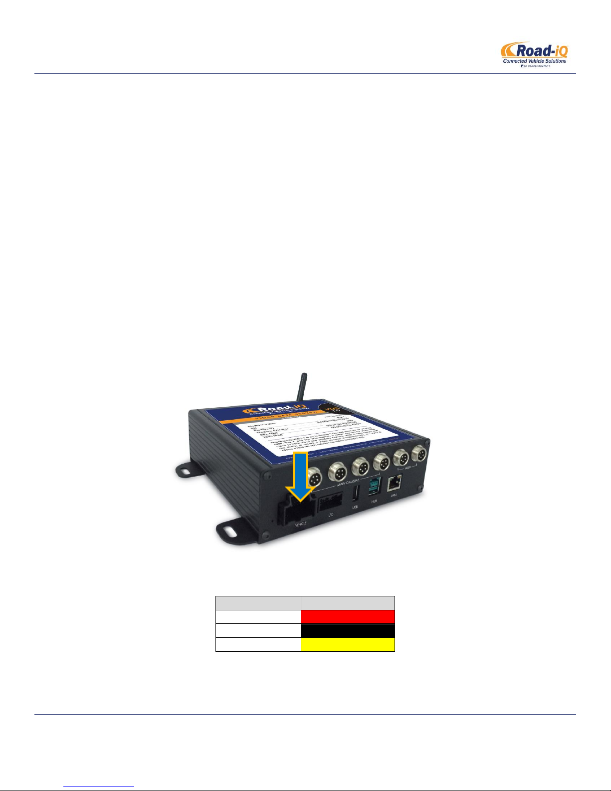
Function
Color
Power
Red
Ground
Black
ACC
Yellow / White
Road-iQ VideoData Server
2.7 MOUNTING THE IPAD
2.7.1 Rosen Mount
2.7.2 RAM Mount
2.7.3 Padholdr Mount
2.8 MOUNTING THE VIDEODATA SERVER & NETHUB
When a mounting location for the Road-iQ VideoData Server has been determined, secure the unit to the
surface using four (4) self-tapping screws through the four (4) mounting feet and screw into the mounting
surface.
2.9 POWERING THE ROAD-IQ VIDEODATA SERVER
Connect the Vehicle Harness to the Road-iQ VideoData Server port labeled “Vehicle”:
The vehicle harness wires needed for this step are colored as follows:
Part Number: X3683
Revised 2/27/2015 P a g e | 17
 Loading...