

Page 1
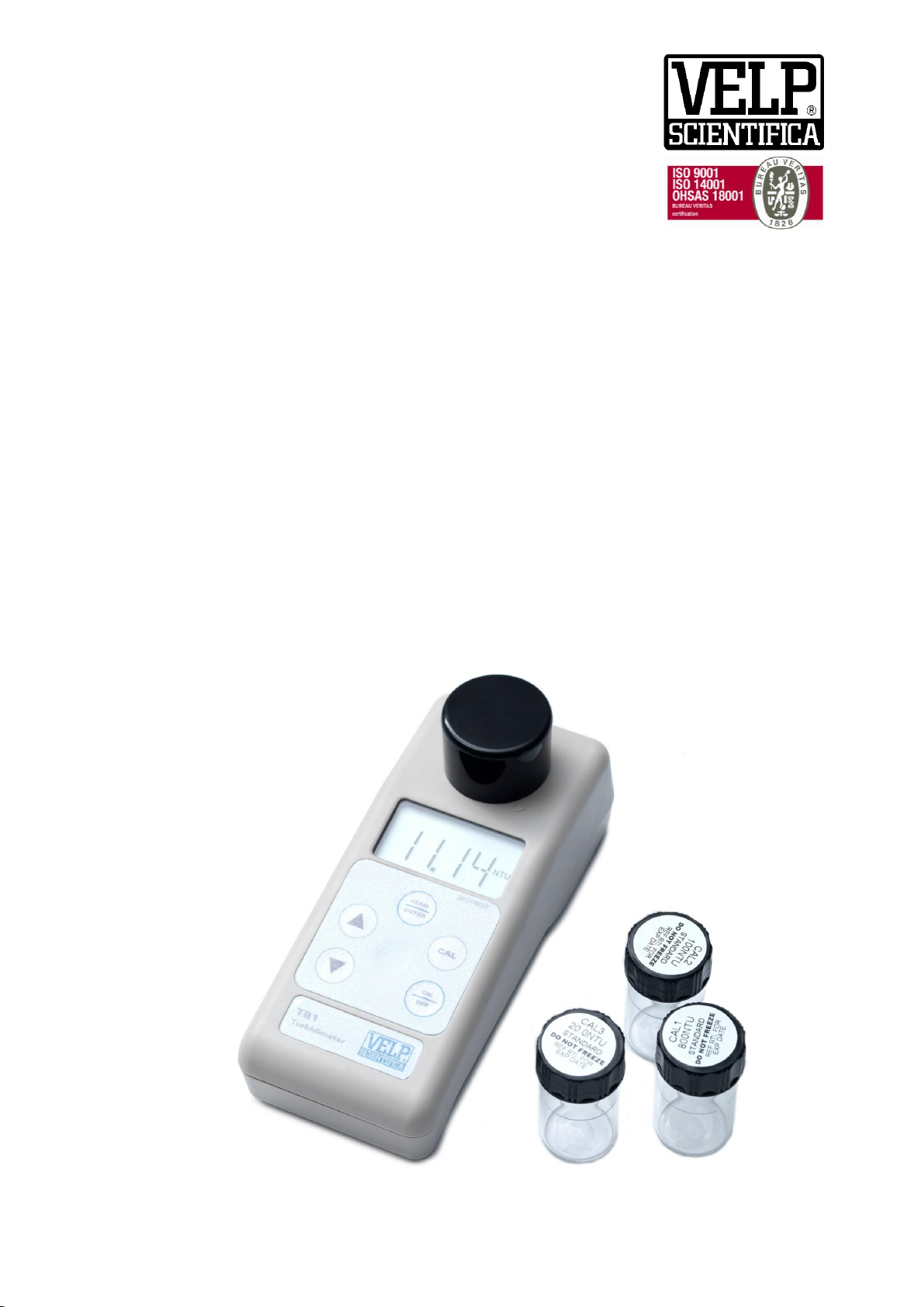
Instruction Manual
TB1
Portable Turbidimeter
VELP SCIENTIFICA
Constant Commitment to
Knowledge Developmen
t
10000208
/A9
Page 2

Velp Scientifica –TB1 Manual
Preface
This manual functions in two ways: first as a step by step guide to help you
operate the waterproof TB1 turbidimeter; second, it serves as a handy
reference guide.
It contains basic instructions that you must follow during the operation,
care and maintenance of the instrument. The safety protection provided by
this equipment may be impaired if it is used in a manner not described in
this manual. It is recommended that all operators should read this manual
prior to working with this instrument.
The manufacturer does not acknowledge any responsibility for an
improper use of the equipment, not responding to directions for use.
Note: The manufacturer, engaged in a continuous improvement of his
products reserves the right to modify any of their characteristics without
notice.
Do not dispose of this equipment as urban waste
Page 3

Velp Scientifica –TB1 Manual
TABLE OF CONTENTS
1 OVERVIEW 1
1.1 Unpacking TB1Meter and Accessories 1
1.2 Display 2
1.3 Keys and Functions 3
1.4 Battery Installation 4
2 TURBIDITY CALIBRATION 5
2.1 Indexing 5
2.2 Calibration Standards 5
2.3 Preparing the standard vials 6
2.4 Calibration Procedure 6
2.5 Restoring Factory Calibration 9
3 TURBIDITY MEASUREMENT 11
3.1 General Information 11
3.2 Turbidity Measurement Procedure 11
3.2.1 Preparation of Sample Vial 12
3.2.2 Measurement Procedure 13
3.3 Single-Shot or Continuous Measurement 14
4 TROUBLESHOOTING GUIDE 16
5 ROUTINE MAINTENANCE 17
5.1 Vials – Handling, Cleaning and Care 17
6 ACCESSORIES 18
7 SPECIFICATIONS 19
8 ADDENDUM 1: TURBIDITY 20
8.1 Definition 20
8.2 Why Is It Important? 20
8.3 Measurement Principle 20
8.4 Nephelometric Turbidity Units (NTU) 21
8.5 Indexing a Vial 21
9 ADDENDUM 2: GUIDE TO GOOD MEASUREMENT TECHNIQUE 22
9.1 Maintain sample vials in good condition 22
9.2 Match Sample Vials 22
9.3 Degassing 23
9.4 Timeliness of Sample 23
9.5 Other Important Sampling Techniques 23
9.6 Calibration 24
9.7 Dilution 24
10 WARRANTY 25
Page 4

Velp Scientifica –TB1 Manual
1
1 OVERVIEW
Thank you for selecting the waterproof portable TB1 turbidimeter. The TB1
allows you to measure turbidity of an aqueous sample in the field. This
instrument operates on the nephelometric principle of turbidity
measurement and is designed to meet the criteria specified in ISO 7027
and DIN 27027 standards (see 8.3 Measurement Principle on page
20).
1.1 Unpacking TB1 Meter and Accessories
The table below indicates the items that you should find in your
turbidimeter shipment.
Item
Quantity
1. Field Portable TB1 Turbidimeter with 4 “AAA” batteries
1
2. Instruction Manual
1
3. Instrument Carrying Case
1
4. Light Shield Cap
1
5. Calibration Set (0.02, 20.0,100, 800 NTU Standards)
1
6. Empty Vials
3
7. Silicone Oil
1
8. Lint free cloth
1
Remove TB1 turbidimeter from the packing carton. Carefully inspect all
items to ensure that no visible damage has occurred during shipment. If
the items you received do not match your order, please contact your
nearest distributor immediately.
WARNING: Extra care should be taken when
unpacking, opening, and handling the calibration
standards and sample vials. Surface scratches or
finger smudges on the vial surface may cause
measurement errors. Handle these items by their
caps only.
Batteries provided with the meter package are to be installed prior to use.
See Section 0 - 1.4 Battery Installation on page 4.
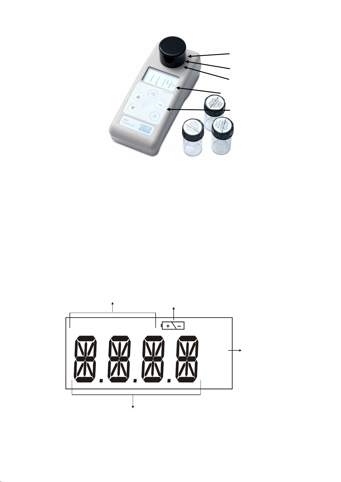
Figure 1 depicts the meter. The three main components of the instrument
are the sample well, the display, and the keypad. The following sections
will describe the functionality of the display and the keypad. The proper
use of the instrument and the sample well will be discussed in later
sections.
Page 5
Velp Scientifica –TB1 Manual
2
Figure 1: Parts of TB1 Turbidimeter
1.2 Display
All the LCD segments and annunciators that can appear on the display are
shown in Figure 2. The display is used for reporting the turbidity reading
and to provide guidance for the operation of the instrument. In addition,
the display has several other annunciators that are used to communicate
error messages and provide user guidance.
CAL 13CAL 24
mg/l
NTU
ppm
%pH
TAvg
14-segment Liquid Crystal Display
Battery Indicator
Calibration
Standards
Units of
Measurement
Figure 2: Customized LCD when switched on
Sample Vial
Sample Well
Index Mark
Liquid Crystal Display
Keypad
Page 6

Velp Scientifica –TB1 Manual
3
1.3 Keys and Functions
The keypad has five keys: ON/OFF, CAL, ▲, ▼, and READ/ENTER.
Keys
Functions
ON/OFF
- Powers on and shuts off the meter. With the auto switch-off
feature the meter automatically shuts off 20 minutes after last
key press.
CAL
- Initiates the calibration mode of the meter. When pressed, the
meter is set to accept the first calibration standard.
- It is also used to exit the calibration mode if the user does not
want to follow the complete calibration procedure.
READ /
ENTER
- When in measurement mode, the READ/ENTER key is used to
perform a measurement.
- Single-shot measurements: When the key is pressed and
released immediately (a quick key stroke of less than 0.3
seconds), the display will blink [-Rd-] for 10 times and then
display the measured value.
- Continuous measurements: If the READ/ENTER key is pressed
and held, the instrument will perform a continuous measurement
during which the display is updated every 2 seconds. This can
be used for indexing vials. (This function is not available in
calibration mode).
After the READ/ENTER key is released, the instrument will
automatically perform a single-shot measurement.
- When in calibration mode, the READ/ENTER key is used to
confirm the measurement for the calibration standards.
▲and▼
- Active only during calibration mode. These keys are used to
select the calibration point in an incremental/ decremental
manner.
NOTE: This meter is also fitted with an auto incrementing
feature, i.e. after the successful calibration of one point it auto
selects the next calibration point, or automatically exits the
calibration mode after the fourth calibration point.
Page 7
Velp Scientifica –TB1 Manual
4
1.4 Battery Installation
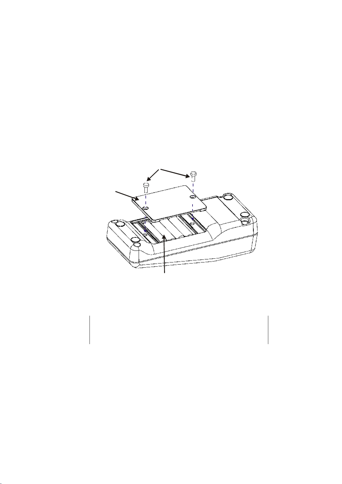
Four AAA-sized batteries are included in your meter’s packaging:
1. Use a Philips screwdriver to remove the two screws holding the
battery cover. See Figure 3.
2. Remove the battery cover.
3. Insert the batteries. Follow the diagram inside the cover for correct
polarity.
4. Replace the battery cover onto its original position using the two
screws removed earlier.
5. The meter is now ready to operate.
Philips Screws
Battery cover
Four 'AAA'-sized batteries
Figure 3: Battery Installation
NOTE:
Dispose used batteries in accordance with your local
regulations.
Page 8

Velp Scientifica –TB1 Manual
5
2 TURBIDITY CALIBRATION
The TB1 turbidimeter was calibrated and tested prior to leaving the factory.
Therefore, it is possible to use the instrument directly out of the box.
However, re-calibration of the instrument is recommended to help you
become familiar with the operation of the instrument and the calibration
procedures. In addition, re-calibration is recommended at least once every
month for optimum accuracy.
It is recommended that you perform a full calibration using all 4 standards
provided to ensure full-range accuracy. The meter kit now includes a set of
prepared SDVB primary standards in plastic bottles which are EPAapproved for meter calibration. This keeps the stock solutions for the 0.02,
20.0, 100 and 800 NTU standards ready to use and offers improved
precision and shelf life. A set of 4 empty vials for the standards are
included in the meter kit. Before using the meter for the first time, verify the
meter calibration by reading back the value for the prepared primary
standard at the appropriate NTU value.
However, the TB1 turbidimeter provides flexibility for you to calibrate at
selected ranges suitable for your application.
In addition, the instrument comes with a light shield cap to shield off stray
light during calibration and measurements.
2.1 Indexing
Due to the high quality of the glass vials provided, indexing is not required.
You only need to align the mark on the vial with the mark on the meter.
However, in order to achieve a better accuracy of the measurement, you
can proceed with indexing of the vials. See Section 8.5 Indexing a
Vial on page 21 for more information.
2.2 Calibration Standards
We recommend that you use the following SDVB primary standard during
calibration to achieve the accuracy stated in this manual:
▪ CAL 1: 800 NTU Calibration Standard
▪ CAL 2: 100 NTU Calibration Standard
▪ CAL 3: 20.0 NTU Calibration Standard
▪ CAL 4: 0.02 NTU Calibration Standard
It is well known that diluted Formazin is unstable. If you choose to use
Formazin to calibrate the instrument, ensure that you are using a fresh
stock suspension of Formazin to achieve the accuracy quoted for the
Page 9

Velp Scientifica –TB1 Manual
6
instrument. The SDVB Calibration standards offered are more stable than
Formazin and have a shelf life until the expiration date on the plastic
bottle. These are primary standards that meet the regulatory requirements
for reporting for ISO and US EPA.
2.3 Preparing the standard vials
Each standard vial should be used with the same standard value (0.02,
20.0, 100, or 800 NTU) for the greatest accuracy. Follow the steps below
at each change of solution.
1. Ensure there are no scratches or marks on the glass vial. If there are
marks that could affect the turbidity measurement, select another vial.
2. Slowly and gently invert the calibration stand plastic bottle five times but
do not shake the bottle as air bubbles can affect the reading.
3. Rinse a clean vial with 3-4 ml of the calibration standard that will be
used in this vial. Invert the capped vial 5 times. Uncap and dispose of the
rinsate.
4. Repeat the rinsing steps and dispose of the rinsate.
5. Fill the vial with the primary standard solution to the fill line and cap the
vial.
6. Clean the exterior of the vial using a lint-free cloth to remove all traces
of liquid, dirt or fingerprints. Remove stubborn smudges with alcohol or a
non-abrasive glass cleaner, and silicone oil can be used to fill small
external scratches on the vial.
7. Repeat Steps 1-6 to prepare the other three standard solutions.
These standard vials can be used to check the meter calibration by
reading back the standard value daily and also be used for calibration
when needed. When the standard reading drifts more than 10% of the
standard’s NTU value, the solution should be replaced with another aliquot
from the plastic bottle following the Preparing the Standard Vials steps.
Page 10

Velp Scientifica –TB1 Manual
7
2.4 Calibration Procedure
When calibration is required fresh standards from the plastic bottle are
recommended for the greatest accuracy. Follow the calibration sequence
from highest, 800 NTU, down to lowest standard, 0.02 NTU. See Section
2.3 “Preparing the standard vials” prior to starting the calibration.
1. Place the TB1 turbidimeter on a flat and level surface.
2. Select the calibration function of the instrument by pressing the CAL
button once. The [CAL] annunciator will blink momentarily and the
meter will prompt for the first calibration standard CAL 1 standard (800
NTU).
3. Insert the CAL 1 standard (800 NTU) into the sample well, aligning the
mark on the vial with the mark on the meter. See Figure 10
4. Press down until the vial snaps fully into the instrument.
5. Cover the vial using the light shield cover.
6. Press READ/ENTER key.
7. The [CAL 1 800 NTU] annunciator will blink for about 12 seconds.
When the instrument has completed calibration for this point, it prompts
you to insert the next calibration standard into the sample well [CAL 2
(100 NTU).
8. Repeat the calibration sequence for each calibration standard.
9. After you successfully calibrate the CAL 4 standard (0.02 NTU), the
display will show [STbY].
10. The meter is now ready to perform next measurement.
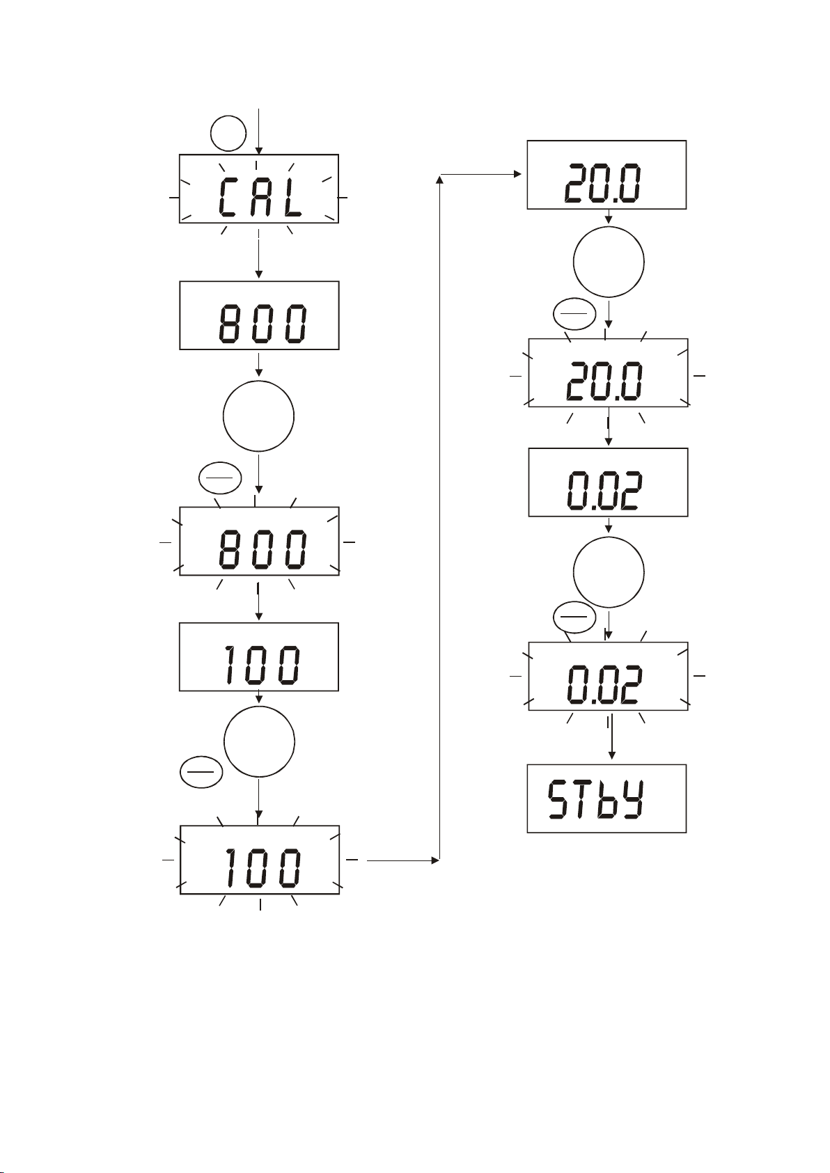
Figure 4 shows the complete calibration sequence.
NOTES:
1. If you wish to exit the calibration mode you may
do so at the end of any step by pressing the CAL
key. The meter will accept only the values
calibrated prior to exiting.
2. You can skip a calibration point by pressing ▲ or
▼ keys and move on to the next calibration point.
3. After a successful calibration of one point, it will
auto select the next calibration point. It will
automatically exit calibration mode after the fourth
calibration point.
4. If an error occurs during calibration, the display
will present an error message. The meter will
abort calibration and return to the measurement
mode without saving the last calibration value.
5. For a list of error messages, refer to Section 4:
Troubleshooting Guide.
Page 11
Velp Scientifica –TB1 Manual
8
CAL 1
800 NTU
NTU
CAL 1
NTU
NTU
CAL 3
CAL 3
NTU
CAL 2
NTU
CAL 2
READ
ENTER
NTU
CAL 1
CAL
Place the CAL 1
standard into the
sample well
Place the next CAL
3 standard into the
sample well
Flashes about
5 times
Flashes about 10
times or more
Flashes about 10
times or more
Flashes about 10
times or more
Flashes about 10
times or more
CAL 3
CAL 4
20.0 NTU
0.02 NTU
NTU
NTU
CAL 4
CAL 4
READ
ENTER
READ
ENTER
Place the next CAL
2 standard into the
sample well
Place the next CAL
4 standard into the
sample well
The TN-100/ T-100 meter is now ready
for measurement
CAL 2
100 NTU
READ
ENTER
Figure 4: Calibration Sequence
Page 12

Velp Scientifica –TB1 Manual
9
2.5 Restoring Factory Calibration
The TB1 turbidimeter allows you to reset the meter back to the factory
default calibration values. This feature is extremely useful when there are
errors in calibration or when you have new calibration standards.
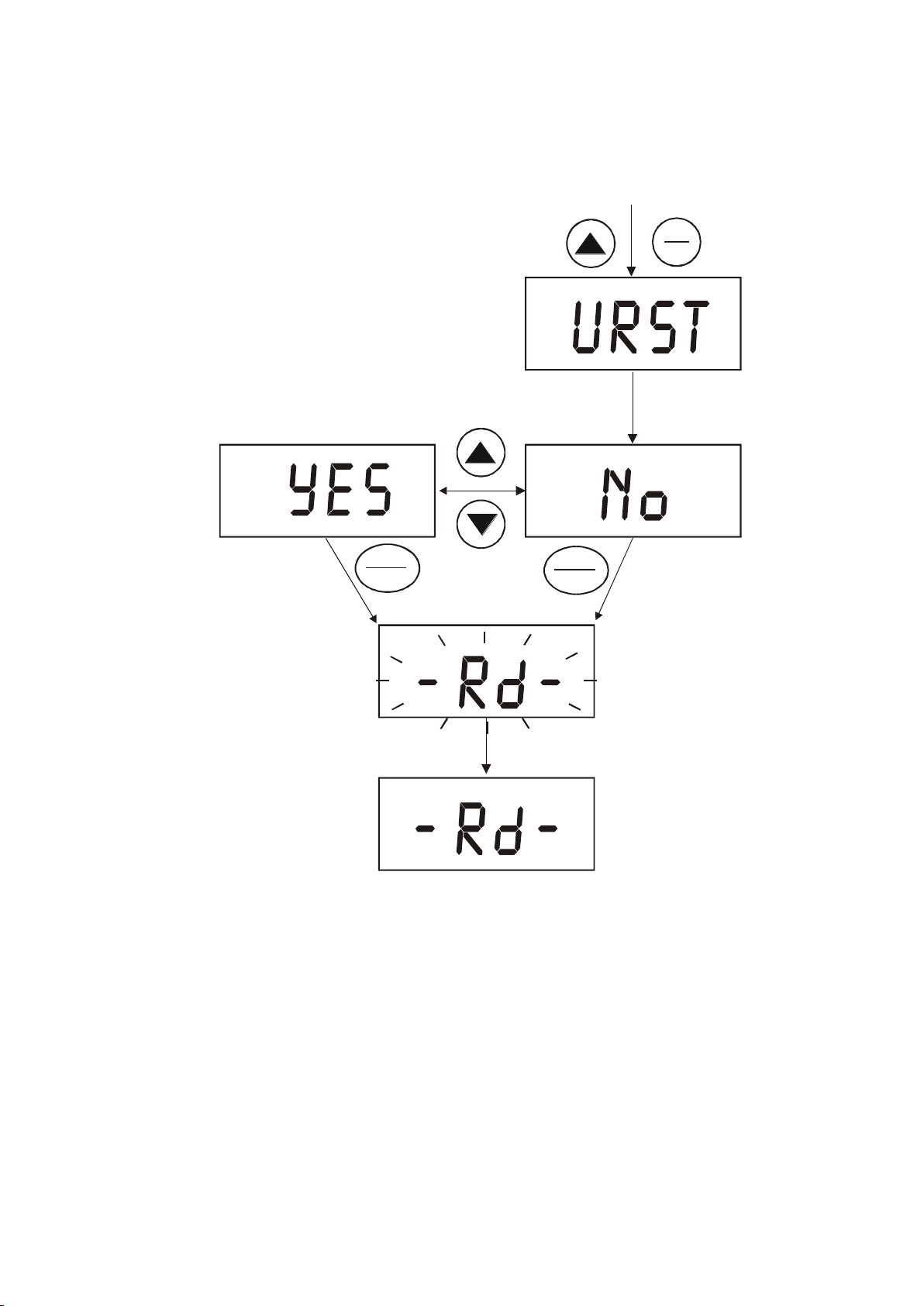
1. With the meter switched off, press ▲ and ON/OFF keys simultaneously
for about 2 seconds.
2. The display will flash [URST] (User-Reset) for 2 seconds and show
[No], which is the default value.
3. Use ▲ or ▼ key to select between [YES] or [No].
▪ [YES] = To restore meter back to factory calibration values
▪ [No] = To retain last calibrated values
4. After selecting [YES] or [No], press READ/ENTER key.
5. The display will flash [--Rd--] 10 times.
6. Once it stops flashing, it will show [--Rd--]. It is now ready to take
turbidity measurements.
Figure 5 shows the sequence for restoring factory calibration values.
Page 13
Velp Scientifica –TB1 Manual
10
READ
ENTER
READ
ENTER
Press and
keys simultaneously and
hold for 2 seconds before
releasing
UP ON/OFF
[-Rd-] will flash 10 times
The meter is now ready for measurement
Press or key to
select or
UP DOWN
YES No
To restore factory
calibration
To retain last
calibration values
without retrieving
factory calibration.
METER OFF
OFF
ON
Figure 5: Restoring Factory Calibration
Page 14
Velp Scientifica –TB1 Manual
11
3 TURBIDITY MEASUREMENT
3.1 General Information
The waterproof TB1 turbidimeter allows you to measure the turbidity of a
grab sample. The turbidity is reported in Nephelometric Turbidity Units
(NTU). Readings above 1000 NTU are outside the range of this
instrument.
NOTE:
Before switching on the TB1 turbidimeter, a sample
vial MUST be placed in the sample well. You can use
any of the calibration standards for this purpose.
The light shield cap provided could be used to cover
the vial during measurements.
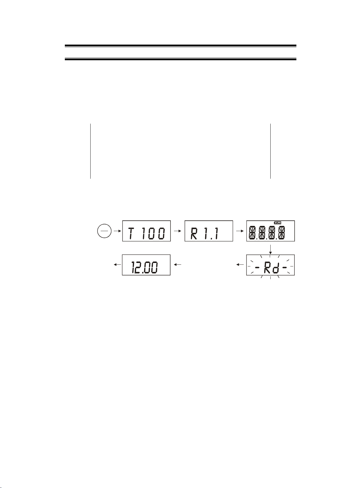
The meter will go through a power sequence as shown in Figure 6.
CAL 13CAL 24
mg/l
NTU
ppm
%pH
TAvg
NTU
OFF
ON
"Rd" will flash 10 times
before a reading appears
(assuming you have
placed a vial into the
sample well of the meter
A reading will only appear
if you have placed a vial
or any of the calibration
standards provided into
the sample well.
Otherwise an error
message "Err 8" will
appear.
Figure 6: Power-up sequence
3.2 Turbidity Measurement Procedure
An accurate turbidity measurement depends on good measurement
techniques. Factors such as clean sample vials, positioning of vial in the
sample well, covering the vial with the light shield cap, meter calibration,
handling of meter, and others, have to be taken into consideration. Please
see Section 0: 5.1 Vials – Handling, Cleaning and Care on page 17 and
Section 9: ADDENDUM 2: Guide to Good Measurement Technique on
page 22 for more information.
Page 15
Velp Scientifica –TB1 Manual
12
3.2.1 Preparation of Sample Vial
1. Grab liquid with the plastic bottle provided.
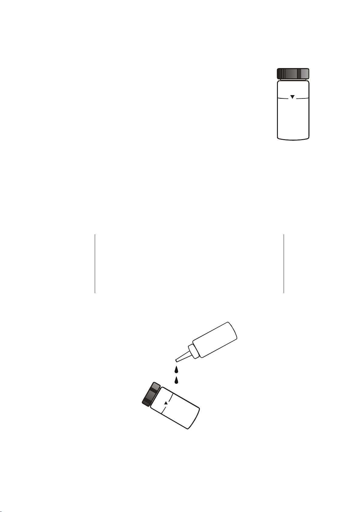
2. Obtain a clean and dry sample vial (Figure 7).
3. Take care to handle the sample vial by the top.
4. Rinse the vial with approximately 10 ml of the sample
water, capping the vial with the black screw cap and
gently inverting it several times. Discard the used sample
and repeat the rinsing procedure two more times.
5. Fill the rinsed vial with the remaining portion
(approximately 10 ml) of the grab sample up to the
mark indicated in the vial. Cap the vial with the
supplied black screw cap.
6. Wipe the vial with the soft, lint-free cloth supplied. Ensure that the
outside of the vial is dry, clean and free from smudges.
7. Apply a thin film of silicone oil (supplied) on the sample vial (see Figure
8). Wipe with a soft cloth to obtain an even distribution over the entire
vial’s surface.
NOTES:
1. The purpose of oiling the vial is to fill small
scratches and to mask the imperfection in the
glass.
2. Do not apply large quantity of oil as this may
collect dirt and dust.
8. You are now ready to place the vial into the meter for measurement.
Figure 8: Apply a thin film of silicone oil
Figure 7:
Sample Vial
Page 16
Velp Scientifica –TB1 Manual
13
3.2.2 Measurement Procedure
1. Place TB1 turbidimeter on a flat and level surface.
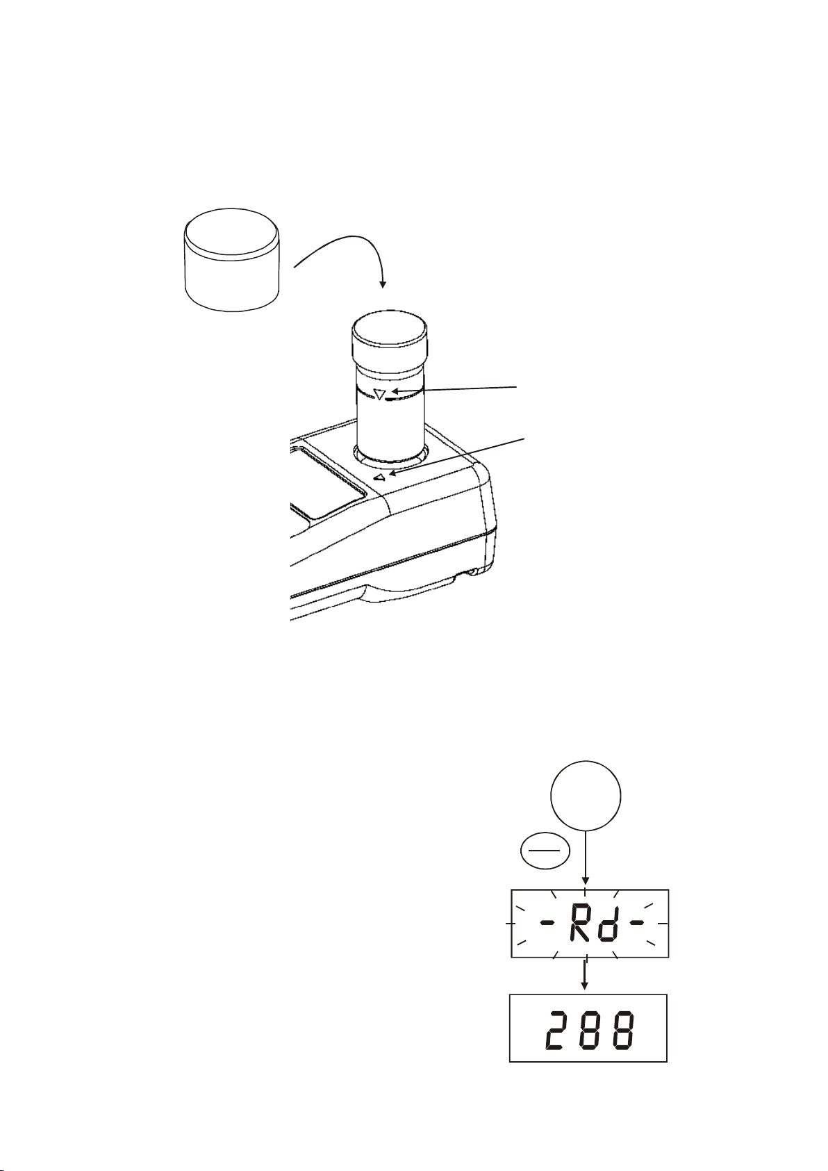
2. Place the sample vial inside the sample well and align the vial’s mark
with the meter’s index mark. See below
Align index mark on
the sample vial with
the index mark on
the TN-100/ T-100
turbidimeter and
push till it is fully
snapped in
IMPORTANT:
Place meter on a flat
and level surface.
DO NOT hold it on
hands while operating
the meter. It may lead to
inaccurate readings
Light shield cap for
covering the vial during
measurements
Figure 8: Align sample vial's mark with meter's index mark
3. Push the vial until it is fully snapped in.
4. Cover the vial with the light shield cap.
5. Turn on the meter by pressing the
ON/OFF key.
6. After the power-sup sequence, the
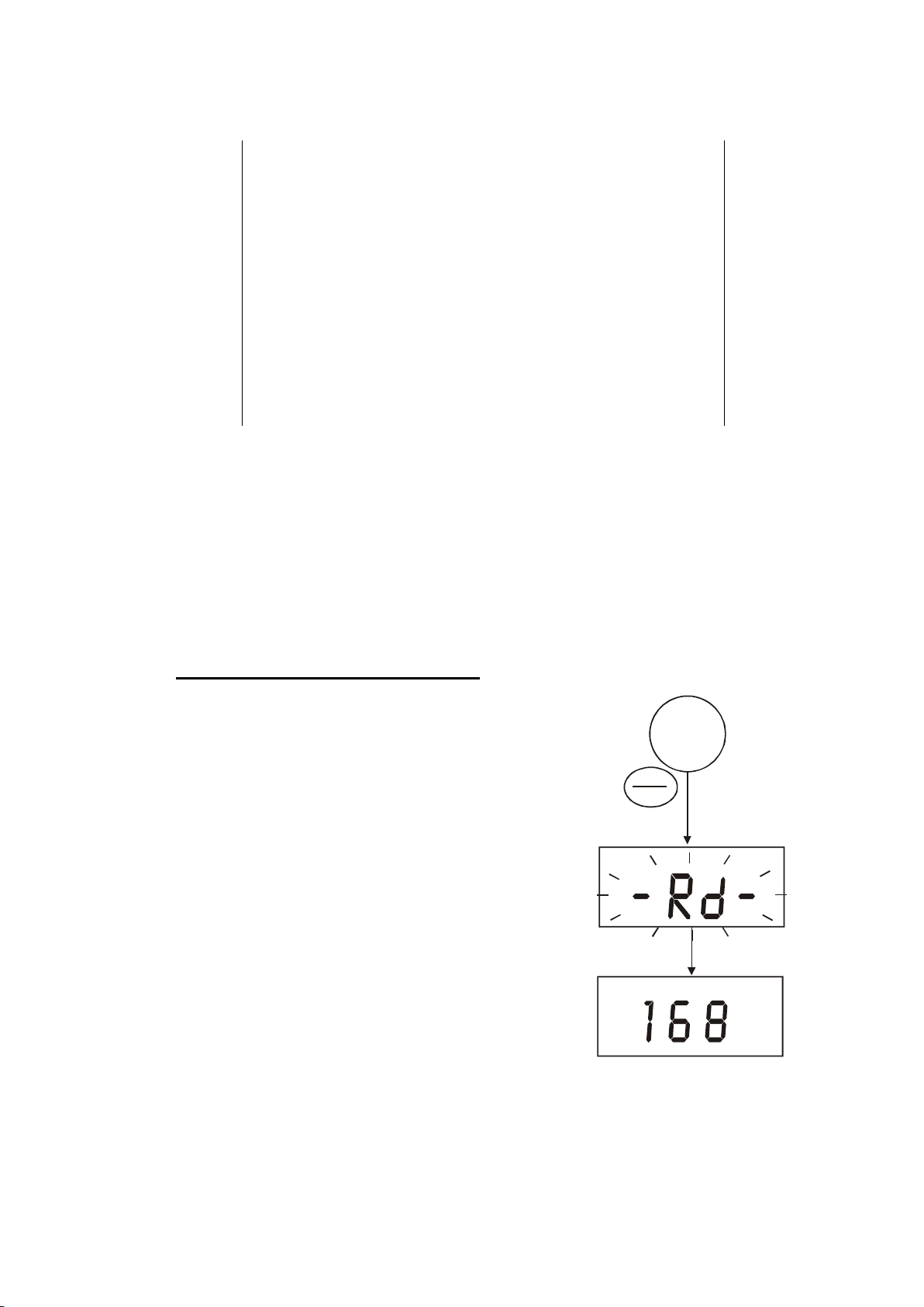
display blinks [--Rd--] for about 12
seconds. See Figure 9.
7. A value will appear. Note the reading.
8. If necessary, please the second sample
vial into the sample well. Remember to
align the vial’s mark with the meter’s
index mark.
9. Press READ/ENTER key. The display
blinks [-- Rd --] and a value will appear.
Note the reading.
10. Repeat steps 2 through 9 for all of your
samples.
Flashes about 10
times
SAMPLE
Unknown
NTU
Place vial
into the
sample well
NTU
READ
ENTER
Measurement mode can start from
either situation:
1. [STbY] after calibration;
2. After powering up the meter
Figure 10: Value tubidity
Page 17
Velp Scientifica –TB1 Manual
14
NOTE:
1. NEVER pour liquid directly into the sample well of
the instrument. Always use a vial. The instrument
will only accurately measure the turbidity of a
sample when vials sealed with the black caps are
used. The black cap serves as both seal and a
light shield.
2. NEVER attempt to clean the sample well. The
optics may be damaged.
3. The instrument will automatically power off 20
minutes after the last key press for battery
conservation.
3.3 Single-Shot or Continuous Measurement
You can use TB1 turbidimeter to take a single reading or perform
continuous measurement. The latter is only used for indexing the vials.
See Section 0 - 8.5 Indexing a Vial on page 21 for more information.
For single-shot measurement:
1. Make sure the meter is sitting on a flat
and level surface and is in measurement
mode. The display shows the last
measured value or [STbY] after exiting
calibration mode.
2. Place sample vial in the sample well.
3. Cover the vial with the light shield cap.
4. Press READ/ENTER key and release
immediately (<0.3 seconds). See Figure .
5. The display will blink [--Rd--] for 10 times
or more and then display the measured
value.
Press key and release
immediately
SAMPLE
Unknown
NTU
Place vial
into the
sample well
NTU
READ
ENTER
Flashes about 10
times
Figure 11: Single-shot measurement
Page 18
Velp Scientifica –TB1 Manual
15
For continuous measurement:
1. Make sure the meter is sitting on a flat and level surface and is in
measurement mode. The display shows the last measured value or
[STbY].
2. Place the sample vial in the sample well.
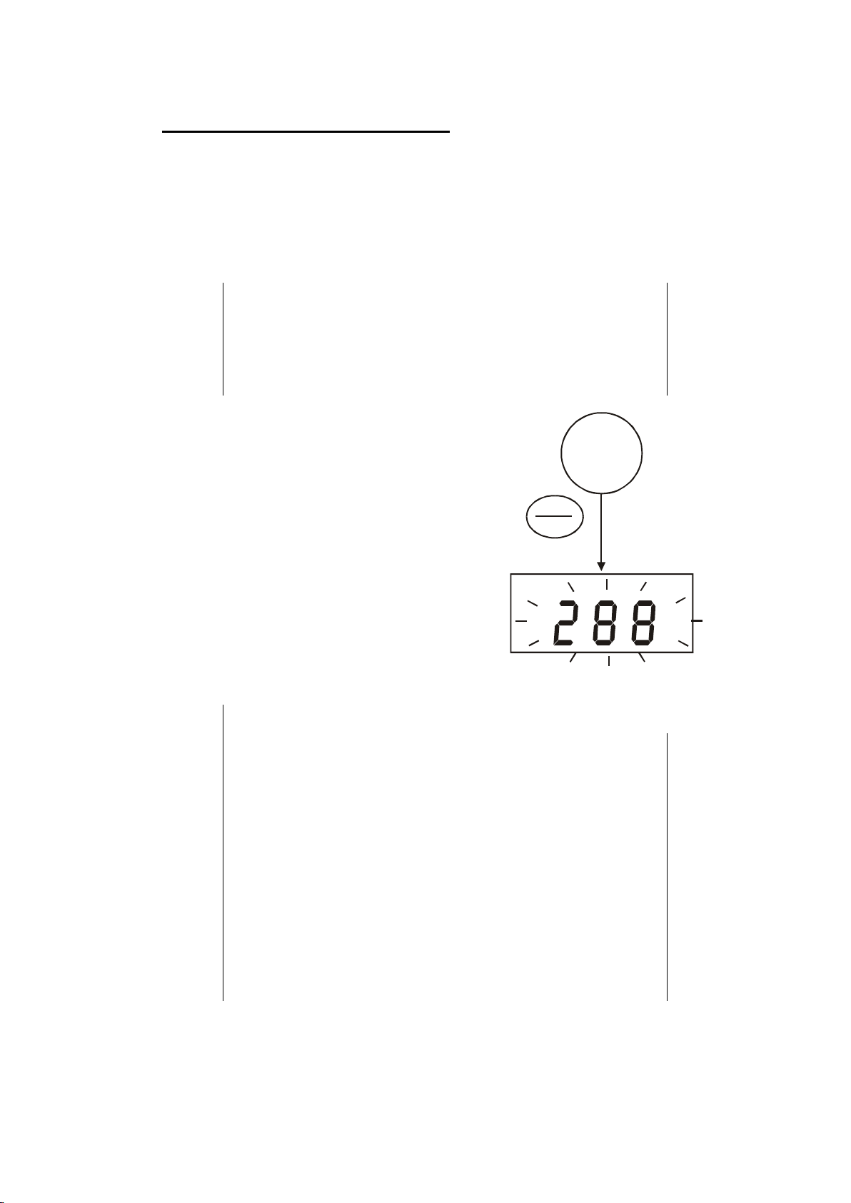
3. Press READ/ENTER key and hold. See Figure 12.
4. Wait for the reading to stabilize before rotating the sample vial.
NOTE:
During continuous measurement, the display is
updated every 2 seconds. The displayed reading
may not be the actual turbidity value. For accurate
measurement, use single-shot measurement.
5. You can rotate the sample vial for
indexing purpose. See Section 0 - 8.5
Indexing a Vial on page 21 for
more information.
6. Once you release the READ/ENTER
key, the meter will automatically
perform a single-shot measurement.
NOTES:
1. After a measurement is completed and the
display is updated, a 4-second recovery time
occurs before the meter can perform another
function. If any key is pressed during the recovery
time, the meter will perform the corresponding
action at the end of the recovery period.
2. When performing a measurement, if the meter
detects stray light exceeding the amount
equivalent to 0.02 NTU in the low range, the
measurement is immediately aborted and an error
message [ERR 8] is displayed. Ensure the vial
sits properly into the sample well. Press the
ENTER/READ key to re-do the measurement.
SAMPLE
Unknown
NTU
Place vial
into the
sample well
Press and hold
NTU
READ
ENTER
You can turn
the vial for
indexing
Figure 12: Continuous measurement
Page 19

Velp Scientifica –TB1 Manual
16
4 TROUBLESHOOTING GUIDE
The TB1 turbidimeter routinely performs self-diagnostics, and will
automatically generate messages to provide you with specific diagnostic
information. These messages are for your use and do not indicate a
reduction in the performance of the instrument or a failure of any
component in the instrument, unless otherwise stated in this list.
LCD
Message
Description
Corrective Actions
ERR 1
Calibration Error. The meter is
unable to recognize the 800 NTU
Calibration Standard.
Ensure to use the correct 800
NTU calibration standard. *
ERR 2
Calibration Error. The meter is
unable to recognize the 100 NTU
Calibration Standard.
Ensure to use the correct 100
NTU calibration standard. *
ERR 3
Calibration Error. The meter is
unable to recognize the 20.0 NTU
Calibration Standard.
Ensure to use the correct 20.0
NTU calibration standard. *
ERR 4
Calibration Error. The meter is
unable to recognize the 0.02 NTU
Calibration Standard.
Ensure to use the correct 0.02
NTU calibration standard. *
ERR 5
Calibration Error. There is not
sufficient signal to achieve the
appropriate resolution in the 01000NTU range.
Re-do calibration with all 4
standards provided. *
ERR 6
General Calibration Failure. There
is not sufficient signal to achieve
the appropriate resolution in the 0100NTU range.
Re-do calibration with all 4
standards provided. *
ERR 7
General Calibration Failure. There
is not sufficient signal to achieve
the appropriate resolution in the 020 NTU range.
Re-do calibration with all 4
standards provided. *
ERR 8
Excessive stray light detected.
Ensure the vial is fully snapped
in the sample well.
Attempting a measurement when
low battery indicator is on.
Replace batteries.
ERR 9
Lamp Failure.
Return unit.
Or
When Turbidity value is above the
measurement range(>1000NTU)
Dilute sample. See Section 0 on
page 24.
Low battery indication. The
batteries need to be replaced.
Replace batteries.
* If an error message appears, take the
appropriate corrective action and re-do the
desired procedure. If the problem persists,
contact Velp or your dealer. See Sections 10
“Warranty” and on page 25.
Page 20

Velp Scientifica –TB1 Manual
17
5 ROUTINE MAINTENANCE
The supplied carrying case is optimal for protecting the instrument. If you do
not plan on leaving the instrument in the supplied carrying case, when not in
use, ensure that the instrument has been turned off and that a clean sample
vial fitted with a black cap has been placed in the sample well.
This will ensure that a minimal amount of dust and/or debris will be able to
settle on the optics of the instrument.
5.1 Vials – Handling, Cleaning and Care
Proper measurement of the turbidity of a sample requires the use of a vial
that is free of marks, smudges, scratches and any bacterial growth.
Therefore, sample vials must be handled with absolute care to avoid
contamination or damage, which might change the optical characteristics of
the glass. Scratches, fingerprints, and water droplets on the sample vial or
inside the sample well can cause stray light interference leading to inaccurate
readings.
Cleaning the vial is accomplished by washing the interior and exterior of the
vial in a detergent solution. Once cleaned, the vial should be rinsed
thoroughly 8 to 10 times with clean distilled water to eliminate the possibility
of detergent buildup and streaking.
Vials can also be acid washed periodically and coated with a special silicone
oil to fill small scratches and mask the imperfections in the glass. Since the
silicone oil required for this application should have the same refractive
characteristics as glass, it is recommended that the oil be obtained from us.
Care should be taken not to apply excessive oil that could attract dirt or
contaminate the sample well of the meter. Once the oil has been applied to
the vial, the excess oil should be removed with a lint-free cloth. The result
should be a sample vial surface with a dry appearance, but with all
imperfections filled with oil.
Sample vials should always be handled from the top or by the cap to avoid
fingerprints or smudges. After a vial has been filled with a sample and
capped, the outside surface should be wiped with a clean, lint-free absorbent
cloth until it is dry. Cleaned and dried vials should be stored with the black
caps on. The vials can be stored in the carrying case. During normal
operation you may use any typical glass cleaner along with a lint free cloth or
tissue (Kimwipes®), to clean the outside of the vials.
Condensation may appear on the vial when your sample is very cold and the
relative air humidity is high. When this happens, the turbidity that you read
may be higher than the actual turbidity due to the light scattered by the
condensate on the vial. If you find yourself in this circumstance, you can
alleviate the problem by either coating the vial with an anti-fogging agent, or
by running warm water over the vial for a short period of time to warm the
sample prior to measurement.
Page 21

Velp Scientifica –TB1 Manual
18
6 ACCESSORIES
The items shown below are recommended accessories and replacement
parts for the instrument.
Description
Code
Waterproof TN-100/ T-100 portable turbidimeter with set of 4
calibration standards (800, 100, 20.0 & 0.02 NTU), set of 3
sample vials, lint-free cloth, silicone oil, batteries – all in a rugged
carrying case.
R109B12150
Calibration Set for normal operation (includes 800, 100, 20.0 &
0.02 NTU Standards)
CE0012020
Sample Vials – pack of 3 vials
CE0012030
Silicone Oil – 10ml
CE0012050
Page 22

Velp Scientifica –TB1 Manual
19
7 SPECIFICATIONS
Model No.
TB1
Measurement Method
ISO 7027 compliant nephelometric method (90°)
Measurement Range
0 to 1000 NTU
Automatic Range Selection
0.01 – 19.99 NTU
20.0 – 99.9 NTU
100 – 1000 NTU
Resolution
0.01 NTU (0 – 19.99 NTU)
0.1 NTU (20 – 99.9 NTU)
1 NTU (100 – 1000 NU)
Accuracy
±2% of reading for 0 to 500 NTU;
±3% of reading for 501 to 1000 NTU.
Repeatability
± 0.01 NTU or ± 1% of reading, whichever is
greater with gel samples
Response Time
< 6 seconds for full step change
Calibration Standards
0.02 NTU; 20 NTU; 100 NTU; 800 NTU
Standardization
EPA-approved polymer-based primary standards
Light Source
Infrared-emitting diode (850 nm wavelength)
Light Source Life
> 1,000,000 tests
Detector
Silicon photovoltaic
Stray Light
< 0.02 NTU
Display
4-digit 14-segments customized liquid crystal
display with annunciators
Sample Cells
Borosilicate glass with screw caps, fill line and
indexing mark.
51 (H) x 25 (Dia) mm ( 2 x 1 in)
Sample Volume Required
10 ml (0.33 oz)
Operating Temperature
Range
0°C to 50°C (32°F to 122°F)
Sample Temperature
Range
0°C to 50°C (32°F to 122°F)
Operating Humidity Range
0-90% RH, non-condensing at 30°C (86°F)
Power Supply
4 x “AAA” Alkaline Batteries (> 1200 readings)
Enclosure Type & Rating:
ABS Plastic / IP67 rated
Insulation Rating
Pollution Degree 2
Weight:
Meter: 200 g (7 oz)
Meter with case: 1.25 kg (2.75 lb)
Dimensions
Meter: 6.8 (W) x 15.5 (L) x 4.6 (H) cm;
(2.7 x 6.1 x 1.8 in)
Meter with Case: 16 (W) x 35 (L) x 12 (H) cm;
(6.3 x 13.8 x 4.7 in)
Page 23

Velp Scientifica –TB1 Manual
20
8 ADDENDUM 1: TURBIDITY
8.1 Definition
Turbidity is defined as an “expression of the optical property that causes
light to be scattered and absorbed rather than transmitted in straight lines
through the sample.”1 That is, turbidity is the measure of relative sample
clarity, not colour.
Water with cloudy or opaque appearance will have high turbidity, while
water that is clear or translucent will have low turbidity. High turbidity value
is caused by particles such as slit, clay, microorganisms, and organic
matter. By definition, turbidity is not a direct measure of these particles but
rather a measure of how these particles scatter light.
8.2 Why Is It Important?
For drinking water application, a turbidity value may give an indication of
presence of bacteria, pathogens, or particles that can shelter harmful
organisms from disinfection process. Therefore, turbidity measurement is
particularly useful for water treatment plants to ensure cleanliness.
In industrial processes, turbidity can be part of quality control measure to
ensure efficiency in treatment or manufacturing process.
8.3 Measurement Principle
There are two internationally accepted standard specifications for turbidity
measurement. These are the international standard ISO 7027 and the US
EPA method 180.1.
Basically the ISO 7027 is a more stringent standard and requires the use
of a monochromatic light source. It also governs the design of a
turbidimeter in the following areas: (1) Light source’s wavelength; (2) Light
sources’ spectral bandwidth; (3) Measuring angle; (4) Aperture angle in
water sample; (5) Distance traversed by incident light and scattered light
within the sample; (6) Calibration standard.
The TB1 turbidimeter follows the ISO 7027 standard whose specification
allows for greater reproducibility of the measured values and greater
agreement between other measuring instruments.
1
Provided by “Standard Methods for the Examination of Water and Wastewater, APHA, AWWA
and WPCF, 16th Edition, 1985.
Page 24
Velp Scientifica –TB1 Manual
21
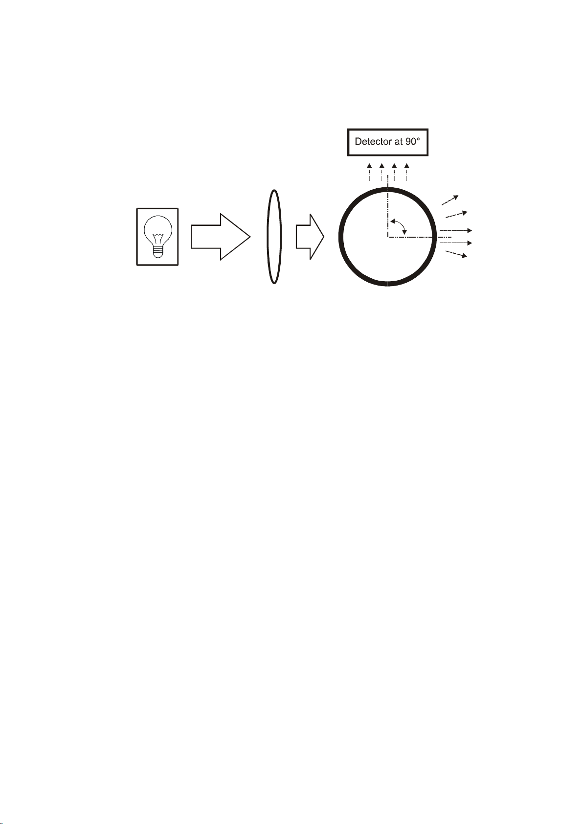
Figure 13 shows the waterproof TB1 turbidimeter basic optical system. It
includes a light source and a detector to monitor the light scattered at 90°
with respect to the incident beam.
90°
Lens
Glass Sample Vial
Transmitted
Light
Scattered Light
Lamp
Figure 13: Basic Nephelometric arrangement for turbidity measurements
8.4 Nephelometric Turbidity Units (NTU)
Nephelometric Turbidity Units (NTU): Unit of measure used when relating
the light scattered by a liquid media to the light scattered by a known
concentration of a standard solution. This unit of measure is recognized as
a measure of the optical clarity of an aqueous sample. NTU is the
accepted unit of measurement for turbidity.
Another unit commonly used to measure turbidity is Formazin Turbidity
Unit (FTU). The two units of measure of turbidity are equivalent:
1 NTU = 1 FTU.
8.5 Indexing a Vial
The United States Environmental Protection Agency (US EPA)
recommends that vials used for turbidimeter calibration or sample
measurement be indexed.
To index a sample vial, slowly rotate the vial throughout one complete
revolution (360°). While rotating the sample vial, observe the display and
locate the position that the vial is in which provides the lowest turbidity
reading. This position is the indexed position of the vial.
Mark this position on the vial (not on the cap) against the mark on the
meter.
After indexing a vial, make sure the vial will always be placed inside the
sample well in the indexed position.
Page 25

Velp Scientifica –TB1 Manual
22
9 ADDENDUM 2: GUIDE TO GOOD MEASUREMENT
TECHNIQUE
Turbidity is a very complex analytical measurement which can be affected
by many factors. Some are inherent in the instrument’s design such as
angle of detection, light beam aperture, incident beam wavelength and
colour sensitivity of the photocell.
However, there are other factors such as stray light, air bubbles and care
of vial, which can be prevented through proper care of equipment and
accessories, and in the operating procedure for measurement. Here are
some points you may want to note:
9.1 Maintain sample vials in good condition
Sample vials must be meticulously clean and free from significant
scratches. It should be treated on the outside with a thin coat of silicone
oil. This is to mask minor imperfections and scratches that may contribute
to stray light. Sample vials should be handled only by the top to avoid dirt
accumulation (or deposits) and fingerprints that might interfere with the
light path.
More information is found in Section 0 - 5.1 Vials – Handling, Cleaning
and Care on page 17.
9.2 Match Sample Vials
Best accuracy and repeatability of turbidity measurement are achieved
using a single, indexed vial. However, for more convenience, different vials
can be used for measurement provided their readings with the same
solution are matched. That is, the meter gives identical readings or within
the specified repeatability and accuracy of the meter.
Select a few vials. After the sample vials are cleaned, fill them with ultralow turbidity water. Allow the sample vials to stand and for air bubbles to
rise. Polish sample vials with silicone oil and take turbidity measurement at
several points while rotating it in the sample well. Find the position where
turbidity reading is the lowest and index it for each vial. Whenever these
sample vials are used, use the indexed mark to position each vial into the
sample well. Choose those vials that match the readings.
NOTE:
Not all vials can be matched because of some
manufacturing variations.
Page 26

Velp Scientifica –TB1 Manual
23
9.3 Degassing
Air or other trapped gases should be removed before measurement.
Degassing is recommended even if no bubbles are visible. There are three
methods commonly used for degassing:
▪ Addition of a surfactant: This involves adding a surfactant to the water
samples to lower the surface tension of the water, thereby releasing
trapped gasses.
▪ Application of a partial vacuum: Partial vacuum can be created by using
simple syringe or vacuum pump. (This is only recommended for ultra-low
turbidity measurement).
▪ Use of an ultrasonic bath: This may be effective in severe conditions or in
viscous samples, but not recommended for ultra-low measurements.
Each of the method above has its own advantages and disadvantages.
For instance, under certain sample conditions, the use of vacuum pump or
ultrasonic bath may actually increase the presence of gas bubbles.
9.4 Timeliness of Sample
Samples should be measured immediately to prevent changes in particle
characteristics due to temperature and settling. Temperature can affect
particles by changing their behavior or creating new particles if precipitates
are formed. Dilution water may dissolve particles or change their
characteristics. It is recommended to take samples only when the
turbidimeter is ready to be operated. Samples should not be drawn and
allowed to sit while the instrument warms up or is being readied.
9.5 Other Important Sampling Techniques
1. Samples should not be violently shaken or agitated as particles can be
broken apart or air may be entrapped into the fluid. Gentle agitation
such as swirling the sample vial is advisable to reduce particle settling.
2. Sample vials should be used only with the instruments for which they
were intended. Do not mix and match.
3. Perform a visual observation of the sample vial every time a
measurement is made. Ensure that there are no visible bubbles in the
sample and the vial is clean and free of scratches.
4. Samples entering the turbidimeter should be at the same temperature
as the process flow samples. Changes in temperature can cause
precipitation of soluble compounds and affect readings.
5. Sample vials should be evaluated with a low turbidity water (after
cleaning) to determine if cells remain matched. If the evaluation
determines that a cell is corrupted, discard the vial. It is recommended
to conduct this evaluation weekly.
6. When in doubt or question about whether a sample vial is too
scratched or stained, throw it away.
Page 27

Velp Scientifica –TB1 Manual
24
9.6 Calibration
1. Do not open the vials with calibration standards.
2. Check that the standards have not expired.
3. Make sure the calibration vials are free of dust, smudges and scratches
before use.
4. Conduct the calibration in the same manner each time. Variations in
how calibration is performed could yield inaccurate measurements.
5. It is very important that the user(s) who perform calibration have been
trained to do so. Creating a Standard Operating Procedure (SOP) for
the user(s) to read, learn, and practice may help to ensure accuracy.
9.7 Dilution
This dilution procedure is necessary only when your turbidity
measurement is above 1000 NTU.
1. To measure the turbidity above 1000 NTU, dilute the sample with
turbidity-free water.
2. Turbidity-free water can be obtained by filtering deionized water
through a < 0.2μm filter membrane with precision-sized pores.
3. Measure the volume of the sample before dilution and record the value
in ml (Vs).
4. Take a known volume (Vd) of dilution water and add it to the sample.
5. Pour 10 ml of the diluted sample in a clean vial and measure the
turbidity of the diluted sample. Record this value in NTU (Td).
6. Calculate the true turbidity (T) of the original sample - in NTU - using
the following formula:
T = Td * (Vs + Vd) / Vs
Example:
▪ Dilute 20 ml of the original sample (whose turbidity is above
1000NTU) with 50 ml of dilution water.
▪ Measure the turbidity of the diluted sample.
▪ If the reading is 300 NTU, the turbidity of the original sample is
1050 NTU. (In this case: Td=300NTU, Vs=20ml, Vd=50ml, so T =
300 * (20+50) / 20 = 300*70/20 = 21000/20 = 1050)
Page 28

Velp Scientifica –TB1 Manual
25
10 WARRANTY
The TB1 meter is supplied with a 2-year warranty from manufacturing
defects and calibration standards for 6 months.
If repair or adjustment is necessary and has not been the result of abuse
or misuse within the designated period, please return – freight pre-paid –
and correction will be made without charge. Velp Scientifica will determine
if the product problem is due to deviations or customer misuse.
Out of warranty products will be repaired on a charged basis.
Exclusions
The warranty on your instrument shall not apply to defects resulting from:
• Improper or inadequate maintenance by customer
• Unauthorized modification or misuse
• Operation outside of the environment specifications of the products
Waterproof Seal: Opening the instrument enclosure (excluding the
battery compartment) may void the warranty.
Page 29

Velp Scientifica –TB1 Manual
26
11. Calibration checklist
Month _________________ Year ______________
Date
Initials
Value
Standard
Comments
Page 30

Velp Scientifica –TB1 Manual
27
Month _________________ Year ______________
Date
Initials
Value
Standard
Comments
Page 31

Page 32

Velp Scientifica –TB1 Manual
Velp Scientifica srl
20865 Usmate (MB) - Italy
Via Stazione, 16
tel. +39 039 628811
fax +39 039 6288120
e-mail: [email protected]
Internet: www.velp.com
Your authorized agent:
 Loading...