

Velp F30620198, F30640198, F30630198 Instruction Manual
1
Instruction Manual
Manuale di istruzioni
Manuel d’instructions
Manual de instrucciones
Bedienungsanleitung
JP Recirculating Water Vacuum Pump
F30620198, F30630198, F30640198
General Information / Informazioni Generali / Informations Générales / Información General /
Allgemeine Hinweise
Before using the unit, please read the following instruction manual carefully.
Prima dell’utilizzo dello strumento si raccomanda di leggere attentamente il seguente manuale operativo.
Avant d’utiliser l’instrument, il est recommandé de lire attentivement le présent manuel d’instructions.
Antes de utilizar el instrumento, le recomendamos que lea con atención el siguente manual de funcionamiento.
Bitte lesen Sie vor Inbetriebnahme des Geräts diese Bedienungsanleitung sorgfältig durch
Do not dispose of this equipment as urban waste, in accordance with EEC directive 2002/96/CE.
Non smaltire l’apparecchiatura come rifiuto urbano, secondo quanto previsto dalla Direttiva 2002/96/CE.
Ne pas recycler l’appareil comme déchet solide urbain, conformément à la Directive 2002/96/CE.
No tirar el aparato en los desechos urbanos, como exige la Directiva 2002/96/CE.
Dieses Gerät unterliegt der Richtlinie 2002/96/EG und darf nicht mit dem normalen Hausmüll entsorgt werden.
This unit must be used for laboratory applications only.
If the product is used in a not specified way by the manufacturer or with non specified accessories, product's safety may be
compromised.
Questo strumento deve essere utilizzato solo per applicazioni di laboratorio.
Se il prodotto viene utilizzato in un modo non specificato o con accessori non specificati dal costruttore stesso, la sicurezza
del prodotto potrebbe essere compromessa.
Cet instrument ne peut être utilisé que pour des applications de laboratoire.
Si le produit est utilisé d'une manière non spécifiée par le fabricant ou accessoires non spécifiés, la sécurité du produit peut
être compromise.
Este dispositivo sólo debe utilizarse para aplicaciones de laboratorio.
Si se utiliza el producto de una manera no especificada o con accesorios no especificados de el fabricante, la seguridad del
producto puede estar comprometida.
Dieses Gerät darf nur für Laboranwendungen verwendet werden.
Wenn das Produkt in einer Weise verwendet wird, die nicht vom Hersteller oder mit unsachgemäßer Zubehör angegeben ,
kann das Produkt die Sicherheit beeinträchtigt werden.

2
This unit has been designed and manufactured in compliance with the following standards:
Lo strumento è stato progettato e costruito in accordo con le seguenti norme:
L’instrument a été conçu et fabriqué conformément aux normes suivantes:
El dispositivo se ha sido diseñado y fabricado de acuerdo con las siguientes normas:
Das Gerät wurde in Übereinstimmung mit folgenden Normen entwickelt und gebaut:
Safety requirements for electrical equipment for measurement, control and for laboratory use
Prescrizioni di sicurezza per apparecchi elettrici di misura, controllo e per l’utilizzo in laboratorio
Règles de sécurité pour appareils électriques de mesurage, de régulation et de laboratoire
Prescripciones de seguridad para equipos eléctricos de medición, control y su uso en laboratorio
Sicherheitsbestimmungen für elektrische Mess-, Steuer-, Regel- und Laborgeräte
EN 61010-1:2010
Electrical equipment for laboratory use
UL 61010-1
General requirement - Canadian electrical code
CAN/CSA-C22.2 No.61010-1
VELP reserves the right to modify the characteristics of its products with the aim to constantly improving their quality.
Nell’impegno di migliorare costantemente la qualità dei prodotti, VELP si riserva la facoltà di variarne le caratteristiche.
Dans le but d’améliorer constamment la qualité de ses produits, VELP se réserve le droit d’apporter des modifications aux
caractéristiques de ceux-ci.
VELP se reserva el derecho de modificar las características de sus productos con el objetivo de mejorar constantemente su
calidad.
VELP behält sich zum Zwecke der ständigen Verbesserung der Produktqualität das Recht auf Änderung der
Geräteeigenschaften vor.

3
Contents / Indice / Index / Índice / Inhalt
1. INTRODUCTION .............................................................................................................................................................. 4
2. ASSEMBLY AND INSTALLATION ................................................................................................................................... 4
3. OPERATING CONTROLS ............................................................................................................................................... 4
3.1 ABSORPTION ................................................................................................................................................................ 4
3.2 TIME RELATED PROGRAMS A OR B ................................................................................................................................ 4
4. MAINTENANCE ............................................................................................................................................................... 5
4.1 CLEANING .................................................................................................................................................................... 5
5. TECHNICAL DATA .......................................................................................................................................................... 5
1. INTRODUZIONE .............................................................................................................................................................. 6
2. MONTAGGIO ED INSTALLAZIONE ................................................................................................................................ 6
3. CONTROLLI DI FUNZIONAMENTO ................................................................................................................................ 6
3.1 NEUTRALIZZAZIONE DI GAS ACIDI ................................................................................................................................... 6
3.2 MODALITÀ TEMPORIZZATE A E B ................................................................................................................................... 6
4. MANUTENZIONE ............................................................................................................................................................. 7
4.1 PULIZIA ........................................................................................................................................................................ 7
5. DATI TECNICI .................................................................................................................................................................. 7
1. INTRODUCTION .............................................................................................................................................................. 8
2. MONTAGE ET INSTALLATION ....................................................................................................................................... 8
3. CONTRÔLES DES OPÉRATIONS .................................................................................................................................. 8
3.1 ABSORPTION ................................................................................................................................................................ 8
3.2 MODALITÀ TEMPORIZZATE A E B ................................................................................................................................... 8
4. ENTRETIEN ..................................................................................................................................................................... 9
4.1 NETTOYAGE ................................................................................................................................................................. 9
5. CARACTÉRISTIQUES TECHNIQUES ............................................................................................................................ 9
1. INTRODUCCIÓN ........................................................................................................................................................... 10
2. MONTAJE E INSTALACIÓN .......................................................................................................................................... 10
3. CONTROLES DE FUNCIONAMIENTO ......................................................................................................................... 10
3.1 NEUTRALIZACIÓN DE GASES ÁCIDOS ............................................................................................................................ 10
3.2 MODOS TEMPORIZADOS A Y B .................................................................................................................................... 10
4. MANTENIMIENTO ......................................................................................................................................................... 11
4.1 LIMPIEZA .................................................................................................................................................................... 11
5. CARACTERÍSTICAS TÉCNICAS .................................................................................................................................. 11
1. EINFÜHRUNG ............................................................................................................................................................... 12
2. MONTAGE UND INSTALLATION .................................................................................................................................. 12
3. BEDIENUNGSELEMENTE ............................................................................................................................................ 12
3.1 NEUTRALISATION VON SAUREN GASEN ........................................................................................................................ 12
3.2 ZEITFAHR-MODUS ...................................................................................................................................................... 12
4. WARTUNG ..................................................................................................................................................................... 13
4.1 REINIGUNG ................................................................................................................................................................ 13
5. TECHNISCHE MERKMALE ........................................................................................................................................... 13
6. WIRING DIAGRAM / SCHEMA ELETTRICO / SCHEMA ELECTRIQUE / ESQUEMA ELÉCTRICO / SCHALTPLAN 14
7. DECLARATION OF CONFORMITY / DICHIARAZIONE DI CONFORMITA / DECLARATION DE CONFORMITE /
DECLARACIÓN DE CONFORMIDAD / KONFORMITÄTSERKLÄRUNG ........................................................... 14
4
1. Introduction
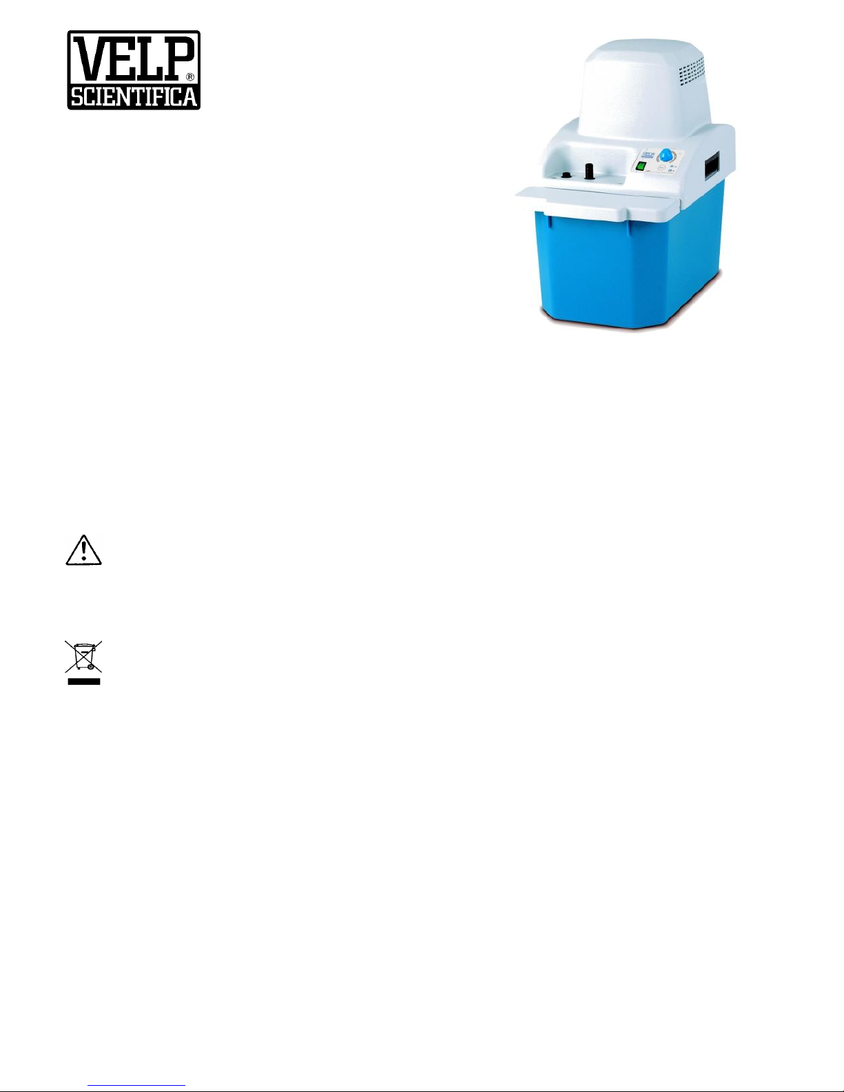
The use of water jet pumps connected to tap is often impeded by a lack of pressure or by their consume which ranges
between 200 and 400 L/h. JP is composed by a plastic water tank in which an impeller driven by an electric motor forces the
water into four water jets developing suction. The water is continuously recirculated and its consumption is nil.
For the movement of equipment use the two handles located in front and rear of the tank. To remove the motor from tank
use the two lateral handles located on the plastic cover. In the upper part of the instrument a tube holder connects to the
internal Venturi ejectors which produce a maximum air flow of 35 l/minute.
The air flow can be regulated from 15 to 35 l/minute by the proper knob. The lateral tube holder can be connected to a
plastic tube for sending residual traces of not neutralized gases to a fume hood or to outside environment. The pump is
equipped by a handy door for the introduction of water and a level indicator for maximum and minimum. A stopcock located
in the rear part of the tank allows the suggested periodical drainage.
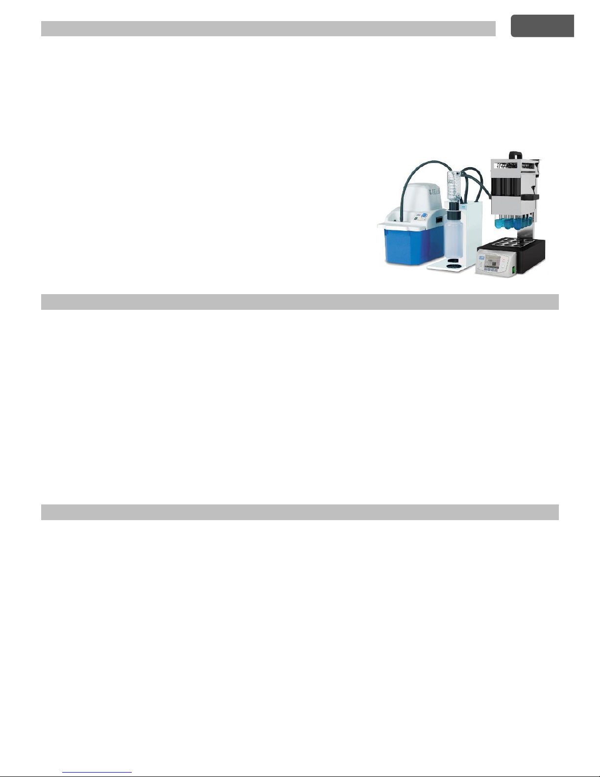
It is proposed for the removal and neutralization of corrosive vapours and
gases evolved during high temperature mineralizations (Kjeldahl, digestions
with nitric, sulfuric or perchloric acid). For this application it is suggested to
use with the pump, the SMS fume neutralizer.
As a vacuum source it can be connected to laboratory equipment as rotating
evaporators, Buchner, Gooch or membrane filters, gel dryers, etc.
The JP vacuum pump produces at the aspiration tubes a residual pressure of
35 mm Hg with a water temperature of 15 °C.
2. Assembly and installation
Upon receipt and after having removed the packaging, please check the integrity of the instrument. The box includes:
JP recirculating water pump Power cable Instruction manual
The equipment is to be connected to the right electric supply by the electric cable connected to the rear of the upper part by
a panel socket with fuse. Ensure that the electric mains is earthed and that the mains socket is easy to reach.
Fill the tank with tap water through the front door up to the maximum level shown by the external indicator. Turn on the
instrument by the lighted main switch.
Air flow and vacuum level are regulated by the proper knob.
Air flow: from 15 to 35 l/minute Vacuum: from room pressure (1 bar) to 0.04 bar
Place the instrument at about 15 cm from the walls.
Attention: If the unit is used for aspiration of corrosive gases, fumes or liquids or for neutralizing acid gases during Kjeldahl
mineralizations adopt the following precautions:
• Use the SMS
• Connect JP to SMS and SMS to the fume cap by using the supplied Viton tube. Viton is a copolymer of vinylidene
fluoride and hexafluoropropylene withstanding temperatures up to 200 °C and highly resistant to chemicals (oils,
solvents, oxidizing agents, strong alkalies and acids) with good mechanical properties (weathering).
3. Operating controls
3.1 Absorption
The widely applied Kjeldahl method for protein content evaluation uses a high temperature (up to 420 °C) mineralization
step with concentrated sulfuric acid and a catalyst.
During the mineralization corrosive toxic gases such as sulfur dioxide (SO2) and sulfur trioxide (SO3) are evolved.
JP is able to suck the gases and vapours evolved by up to 20 Kjeldahl digestion tubes. The pump can be connected to SMS
fume neutralizer which removes acid gases by three steps (condensing, neutralization and absorption) allowing a correct
disposal without emission of toxic substances to the environment (air or water drain).
3.2 Time related programs A or B
The efficiency of fume removal equipment SMS is related to the time of residence of fumes deriving from digestion in the
various stages. If the digestion test tubes with the samples and reagents are introduced in a heating block when this is hot
(normally 420 °C) a large amount of acid fumes is developed in the first minutes. In the following minutes the volume of
fumes is reduced.
Thus in the first phase of digestions it is necessary to dispose of a large capacity of gas removal that can be reduced lately
for a better yield of the system for gas abatement.
This is the reason of the possibility of selection of an optimal sucking power on the JP related to the different phases of
digestion and to the number of digested samples. It is possible to select a work program of JP which changes automatically
the air flow during the digestion and in relation to the used heating block.
EN
5
Program Digester
A DK6, DK8, DK6/48, DKL8
B DK20/26, DK20, DK42/26, DKL12, DKL20, DKL42/26
When the pump is turned on by the general switch a continuous operation is possible with a sucking capacity which is
selected by the purposely devised knob. The push-button Set located on the front panel allows the choice of two different
time related programs (A or B) with programmed air flows.
The operation of one of the two programs is shown by the lighting of a led.
Time related program A - During the first 10 min. of operation the air flow is 50% of the maximum and then lowers to 25%
Time related program B - During the first 10 min. of operation the air flow is 100% of the maximum and then lowers to 50%
NOTE: times and flows are defined on the basis of sample and reagents amounts described by the methods of VELP
Scientifica manuals and for the introduction of digestion test tubes in the heating block when the digestion temperature is
almost reached.
4. Maintenance
In compliance with the product guarantee law, repairs to our units must be carried out in our factory, unless previously
agreed otherwise with local distributors. The instrument must be transported in its original packaging and any indications
present on the original packaging must be followed (e.g. palletized).
• Replace, periodically the tap water in the tank.
• During operation, if necessary, replace the level of water in the tank up to the maximum level and no more to avoid
spillages. A level of water lower than the minimum can compromise pump efficiency.
During long idle periods it is suggested to empty completely the tank and to wash with tap water also the immersed rotating
part. In the case of use for aspiration of fumes deriving from Kjeldahl mineralizations with a connection to fume neutralizer
Scrubber SMS it is suggested to perform this simple maintenance at the end of each working day.
4.1 Cleaning
Disconnect the unit from the power supply and use a cloth dampened with an non-inflammable non-aggressive detergent.
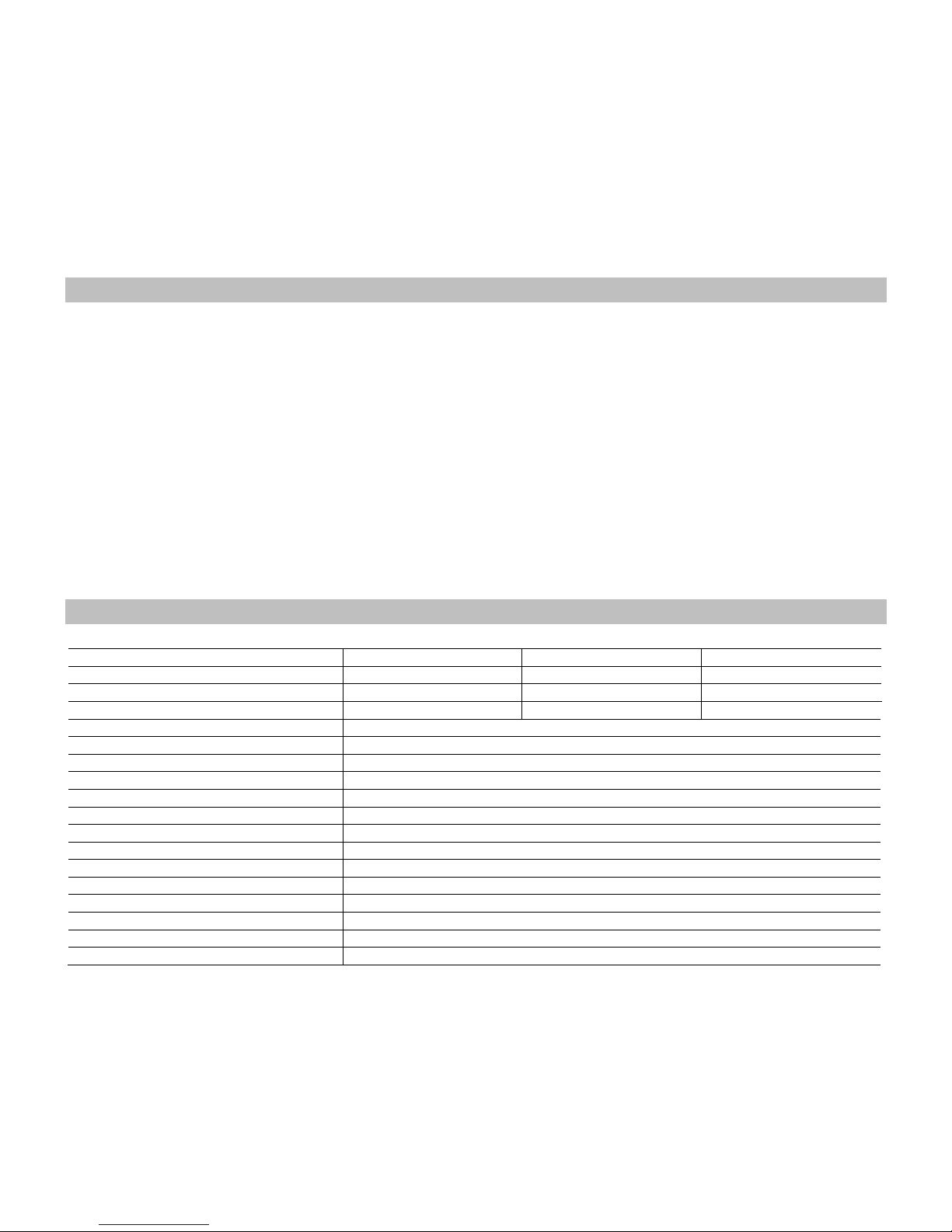
5. Technical data
Code
F30620198
F30630198
F30640198
Power supply
230V/50Hz +/- 10%
230V/60Hz +/-10%
115V/60Hz +/-10%
Fuses
2 x T3,15A L 250V
2 x T3,15A L 250V
2 x T5A L 250V
Power
220 W
330 W
220 W
Dimensions (WxHxD)
250x400x370 mm
Weight
10 kg (empty tank)
Max. air flow
35 Nl/1’
Flow regulation
from 15 to 35 Nl/1’
Vacuum regulation
from 1 to 0.04 bar
Residual pressure
35 mm Hg with a water temperature in the tank = 15°C
Liquid volume
Min. 9 L - Max. 11 L
Working programs
2
Enviromental temp. range
from 0 to 40°C
Max humidity
80%
Pollution degree EN61010-1
2
Overvoltage category EN61010-1:2010
II
Max altitude
Up to 2000 m
Noise level
75 dBA
 Loading...