

Page 1
1
Instruction Manual
Manuale di istruzioni
Manuel d’instructions
Manual de instrucciones
Bedienungsanleitung
指导手册
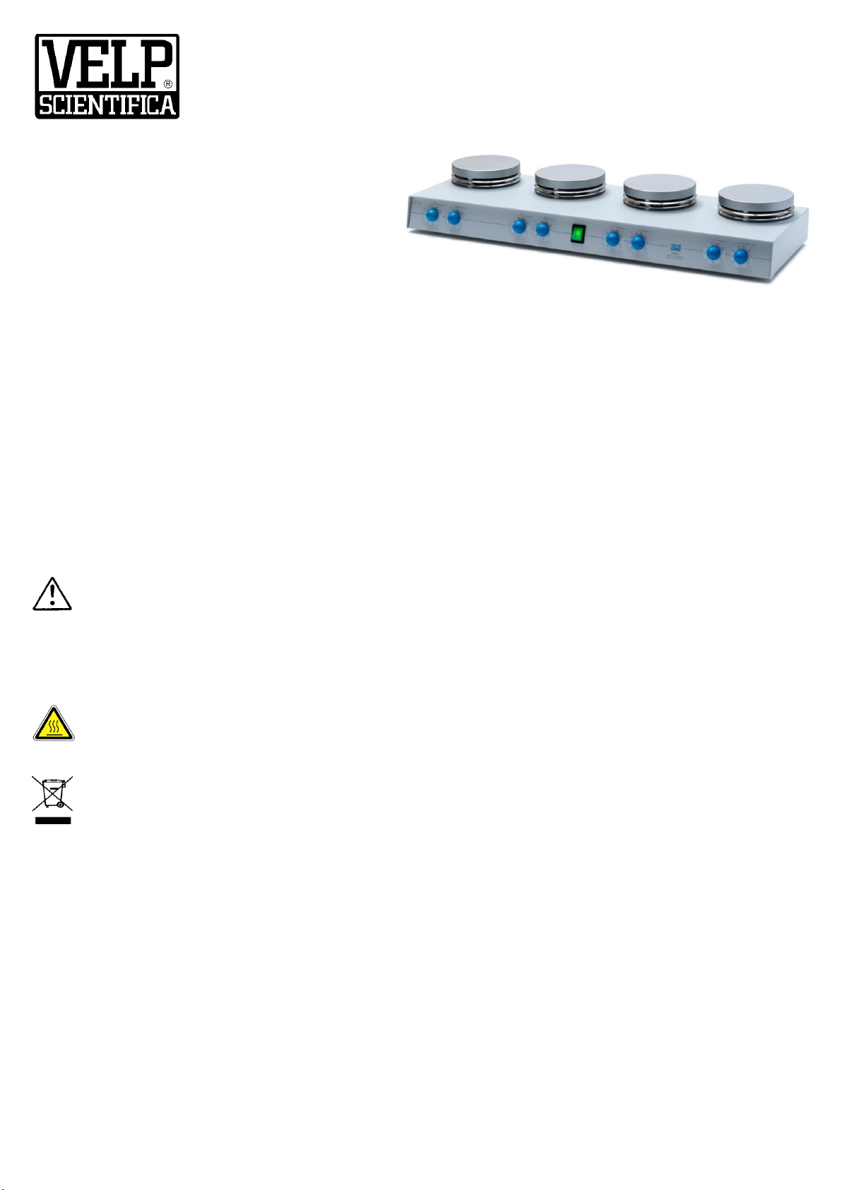
AM4 Heating Magnetic Stirrer, multiple positions
F20500420
General Information / Informazioni Generali / Informations Générales / Información General /
Allgemeine Hinweise / 一般信息
Before using the unit, please read the following instruction manual carefully.
Prima dell’utilizzo dello strumento si raccomanda di leggere attentamente il seguente manuale operativo.
Avant d’utiliser l’instrument, il est recommandé de lire attentivement le présent manuel d’instructions.
Antes de utilizar el instrumento, le recomendamos que lea con atención el siguiente manual de funcionamiento.
Bitte lesen Sie vor Inbetriebnahme des Geräts diese Bedienungsanleitung sorgfältig durch
在使用本装置之前,请仔细阅读以下使用说明书。
Caution, hot surface! / Attenzione, superficie calda! / Attention, surface chaude! / Prudencia, superficie caliente! /
Vorsicht, heiße Oberfläche! / 注意,热的表面!
Do not dispose of this equipment as urban waste, in accordance with EEC directive 2002/96/CE.
Non smaltire l’apparecchiatura come rifiuto urbano, secondo quanto previsto dalla Direttiva 2002/96/CE.
Ne pas recycler l’appareil comme déchet solide urbain, conformément à la Directive 2002/96/CE.
No tirar el aparato en los desechos urbanos, como exige la Directiva 2002/96/CE.
Dieses Gerät unterliegt der Richtlinie 2002/96/EG und darf nicht mit dem normalen Hausmüll entsorgt werden.
根据 EEC 指令 2002/96/CE,请不要将本设备作为城市垃圾处理。
This unit must be used for laboratory applications only.
The manufacturer declines all responsibility for any use of the unit that does not comply with these instructions.
Questo strumento deve essere utilizzato solo per applicazioni di laboratorio.
La società produttrice declina ogni responsabilità sull’impiego non conforme alle istruzioni degli strumenti.
Cet instrument ne peut être utilisé que pour des applications de laboratoire.
Le fabriquant décline toute responsabilité en cas d’utilisation non conforme aux instructions concernant ces instruments.
Este dispositivo sólo debe utilizarse para aplicaciones de laboratorio.
El fabricante declina toda responsabilidad por el uso no conforme a las instrucciones de los dispositivos.
Dieses Gerät darf nur für Laboranwendungen verwendet werden.
Der Hersteller lehnt jede Haftung für unsachgemäße Verwendung oder Nichtbeachtung dieser Bedienungsanleitung ab.
本装置必须仅用于实验室应用。
制造商对任何不符合这些说明的使用不承担任何责任。
Page 2

2
This unit has been designed and manufactured in compliance with the following standards:
Lo strumento è stato progettato e costruito in accordo con le seguenti norme:
L’instrument a été conçu et fabriqué conformément aux normes suivantes:
El dispositivo se ha sido diseñado y fabricado de acuerdo con las siguientes normas:
Das Gerät wurde in Übereinstimmung mit folgenden Normen entwickelt und gebaut:
本装置的设计和制造符合以下标准。
Safety requirements for electrical equipment for measurement, control and for laboratory use
Prescrizioni di sicurezza per apparecchi elettrici di misura, controllo e per l’utilizzo in laboratorio
Règles de sécurité pour appareils électriques de mesurage, de régulation et de laboratoire
Prescripciones de seguridad para equipos eléctricos de medición, control y su uso en laboratorio
Sicherheitsbestimmungen für elektrische Mess-, Steuer-, Regel- und Laborgeräte
测量、控制和实验室用电气设备的安全要求
IEC/EN 61010-1
IEC/EN 61010-2-051
Electrical equipment for laboratory use
UL 61010-1
General requirement - Canadian electrical code
CAN/CSA-C22.2 No.61010-1
VELP reserves the right to modify the characteristics of its products with the aim to constantly improving their quality.
Nell’impegno di migliorare costantemente la qualità dei prodotti, VELP si riserva la facoltà di variarne le caratteristiche.
Dans le but d’améliorer constamment la qualité de ses produits, VELP se réserve le droit d’apporter des modifications aux
caractéristiques de ceux-ci.
VELP se reserva el derecho de modificar las características de sus productos con el objetivo de mejorar constantemente su
calidad.
VELP behält sich zum Zwecke der ständigen Verbesserung der Produktqualität das Recht auf Änderung der
Geräteeigenschaften vor.
VELP 保留修改其产品特性的权利,目的是不断提高其质量。
Safety Regulations / Norme di Sicurezza / Consignes de Securité / Advertencias de Seguridad / Sicherheitshinweise
/ 安全条例
The plug disconnects the instrument. Therefore, place the instrument where it can be quickly disconnected.
La spina è il mezzo di disconnessione dell’apparecchio. Pertanto, non posizionare l’apparecchio in modo che sia difficile
azionare il mezzo di disconnessione.
Le bouchon est le moyen de déconnexion de l'appareil. Par conséquent, placer l'appareil où il peut être rapidement
débranché.
El tapón es el medio de desconexión del dispositivo. No coloque el dispositivo en una forma que es difícil de desconectar.
Der Stecker trennt das Gerät. Daher Stellen Sie das Instrument, wo es schnell getrennt werden kann.
该插头可以断开仪器的连接。因此,要把仪器放在可以快速断开的地方。
Hotplate temperature: up to 370 °C. Temperatura piastra riscaldante: fino a 370 °C. Température de la plaque chauffante:
jusqu'à 370 °C. Temperatura de la placa calefactora: hasta 370 °C. Temperaturbereich Heizplatte: bis zu 370 °C. 热板温度
:最高可达 370℃。
The heated solution may release toxic, dangerous or poisonous gases. Adequate safety measures must be taken, in
accordance with the safety regulations in force, including the presence of hood and personal protective equipment (masks,
gloves, goggles, etc.).
Le sostanze riscaldate potrebbero emanare gas tossici e/o pericolosi e/o velenosi. Adeguate misure di sicurezza devono
essere prese, in accordo con le normative di sicurezza dei prodotti in lavorazione e/o vigenti nei laboratori, compresa la
presenza di cappe aspiranti e mezzi di protezione individuale (maschere, guanti, occhiali, camici, ecc.).
La solution chauffée peut libérer gaz toxiques ou dangereux. Des mesures de sécurité adéquates doivent être prises, en
conformité avec les règlements de sécurité en vigueur, compris la présence de la hotte de laboratoire et équipements de
protection individuelle (masques, gants, lunettes, etc.).
Las sustancias calentadas pueden emitir tóxicos o peligrosos gas. Medidas de seguridad adecuadas deben ser adoptadas,
de acuerdo con las normas de seguridad vigentes en los laboratorios, incluyendo la presencia de la campana de humos y el
equipo de protección personal (mascarillas, guantes, gafas, etc.)
Die erwärmte Lösung kann giftige oder gefährliche Gase freigeben. Angemessene Sicherheitsmaßnahmen zu treffen,
werden in Übereinstimmung mit den geltenden Sicherheitsvorschriften, einschließlich der Anwesenheit Dunstabzug und
persönliche Schutzausrüstungen (Masken, Handschuhe, Schutzbrille, etc.).
加热后的溶液可能会释放出有毒、危险或有害的气体。必须按照现行的安全规定采取适当的安全措施,包括配备头罩和个人
防护设备(口罩、手套、护目镜等)。
Page 3

3
Beware of the effect of the magnetic field on cardiac pacemakers and data media.
Prestare attenzione agli effetti del campo magnetico.
Veuillez tenir compte de l'influence du champ magnétique sur les stimulateurs cardiaques ou les supports de données.
Tenga en cuenta los efectos del campo magnético sobre marcapasos o portadores de datos, entre otros.
Beachten sie die Auswirkungen durch das Magnetfeld auf z.B. Herzschrittmacher oder Datenträger.
谨防磁场对心脏起搏器和数据媒体的影响
Position the instrument on a flat surface, with a distance from the wall of 30 cm (at least).
Posizionare lo strumento su superfici piane, ad una distanza dalle pareti di almeno 30 cm.
Positionner l'appareil sur une surface plat, avec une distance de la paroi de 30 cm (au moins).
Coloque la unidad sobre una superficie plana, con una distancia de la pared de 30 cm (por lo menos).
Stellen Sie das Gerät auf einer ebenen Fläche mit einem Abstand zur Wand von 30 cm (mindestens).
将仪器放置在一个平坦的表面上,与墙壁的距离为 30 厘米(至少)。
Do not use with explosive and dangerous materials for which the equipment is not designed. The stirrer must not be used in
explosive atmospheres, in bain-marie and to stir combustible liquids that have a low combustion temperature. The minimum
fire point of flammable solution is 750 °C. Only small amounts (< 50 ml) of flammable liquid can be used with the device.
Vietato l’uso con materiale esplosivo e pericoloso per cui l’apparecchio non è progettato. L’agitatore non può essere
impiegato in atmosfere esplosive, a bagno maria e per agitare liquidi combustibili a bassa temperatura di combustione. Il
minimo fire point delle sostanze infiammabili è 750 °C. Solo piccole quantità (< 50 ml) di liquido infiammabile possono
essere utilizzate con l’apparecchio.
Ne pas utiliser avec des matières explosives et dangereuses pour lesquelles l'équipement n'est pas conçu. L'agitateur ne
peut pas être utilisé dans des atmosphères explosives, dans un bain d'eau et pour remuer les combustibles liquides avec la
température de combustion bas. Le point minimale de feu de solution inflammable est de 750 °C. Seules de petites
quantités (<50 ml) de liquide inflammable peuvent être utilisés avec l'appareil.
No debe utilizarse con materiales explosivos y peligrosos para los que el equipo no está diseñado. El agitador no puede ser
utilizado en ambientes explosivos, en baño de agua y para agitar combustibles con una baja temperatura de combustión. El
punto mínimo de inflamación de las sustancias inflamables es de 750 °C. Sólo cantidades pequeñas (<50 ml) de líquido
inflamable pueden ser utilizade con el dispositivo.
Nicht mit explosivem Material zu verwenden, für die das Gerät nicht ausgelegt ist. Das Gerät kann nicht in
explosionsgefährdeten Bereichen eingesetzt werden, in einem Wasserbad und rühren für flüssige Brennstoffe mit niedrigen
Verbrennungstemperatur. Die minimale Brennpunkt von brennbaren Lösung beträgt 750 °C. Nur geringe Mengen (<50 ml)
von brennbaren Flüssigkeit kann mit dem Gerät verwendet werden.
不要与设备未设计的爆炸性和危险材料一起使用。搅拌器不得在爆炸性环境中使用,不得在蒸馏器中使用,不得用于搅拌燃
烧温度低的可燃液体。易燃溶液的最低燃点为 750℃。只有少量(<50毫升)的易燃液体可以与本装置一起使用。
It is responsibility of the user appropriately decontaminate the instrument in case of dangerous substances fall on or in it.
It is also responsibility of the user to use safety substances for cleaning or decontaminating, which do not react with internal
parts of the instrument or with the material contained in it. In case of doubts on the compatibility of a cleaning solution,
contact the manufacturer or local distributor.
È responsabilità dell’utilizzatore un’appropriata decontaminazione in caso di versamento di sostanze pericolose sul o dentro
l’apparecchio. È inoltre responsabilità dell’utilizzatore l’uso di sostanze decontaminanti o per la pulizia che non producano
pericolo a causa di reazioni con parti dell’apparecchio o con il materiale in esso contenuto. In caso di dubbio sulla
compatibilità di un agente pulente o decontaminante, contattare il produttore o un distributore locale.
Est responsabilité de l'utilisateur la décontamination en cas de déversement de matières dangereuses sur ou à l'intérieur de
l'équipement. Est responsabilité de l'utilisateur à utiliser des substances qui ne produisent pas de danger pour le nettoyage
ou de décontamination, qui ne réagissent pas avec les parties internes de l'appareil ou avec la matière qu'il contient. En cas
de doute sur la compatibilité d'une solution de nettoyage, contactez le fabricant ou le distributeur local.
Es responsabilidad del usuario una descontaminación adecuada en caso de derrame de sustancias peligrosas en o dentro
el equipo. Es responsabilidad del usuario también utilizar sustancias que no producen peligro para limpiar o descontaminar,
que no reaccionan con las partes internas del instrumento o con el material contenido en él. En caso de duda sobre la
compatibilidad de una solución de limpieza, póngase en contacto con el fabricante o el distribuidor local.
Der Benutzer ist dafür verantwortlich, für die ordnungsgemäße Dekontamination beim Freiwerden gefährlicher Stoffe auf
oder im Inneren des Geräts. Der Benutzer ist dafür verantwortlich, für die Reinigung oder Dekontaminierungsmitteln, die
nicht mit internen Teile des Gerätes oder mit dem Material in ihm enthaltenen reagieren. Im Zweifelsfall über die
Vereinbarkeit einer Reinigungslösung den Hersteller, den Vertreiber oder den Händler.
如果有危险物质落在仪器上或里面,用户有责任对仪器进行适当的净化。
用户也有责任使用安全的物质进行清洁或去污,这些物质不会与仪器的内部零件或其中的材料发生反应。如果对清洁液的兼
容性有疑问,请联系制造商或当地经销商。
Page 4

Page 5

5
Contents / Indice / Index / Índice / Inhalt / 指数
1. INTRODUCTION .............................................................................................................................................................. 7
2. ASSEMBLY AND INSTALLATION ................................................................................................................................... 7
2.1 ELECTRICAL CONNECTIONS .................................................................................................................................................................. 7
2.2 START-UP ........................................................................................................................................................................................ 7
3. OPERATING CONTROLS ............................................................................................................................................... 7
3.1 ERROR MESSAGES .............................................................................................................................................................................. 7
4. MAINTENANCE ............................................................................................................................................................... 8
4.1 CLEANING ........................................................................................................................................................................................ 8
5. TECHNICAL DATA .......................................................................................................................................................... 8
6. ACCESSORIES / SPARE PARTS ................................................................................................................................... 8
1. INTRODUZIONE .............................................................................................................................................................. 9
2. MONTAGGIO ED INSTALLAZIONE ................................................................................................................................ 9
2.1 COLLEGAMENTO ALLA RETE ELETTRICA ................................................................................................................................................... 9
2.2 AVVIO ............................................................................................................................................................................................. 9
3. CONTROLLI DI FUNZIONAMENTO ................................................................................................................................ 9
3.1 MESSAGGI DI ERRORE ......................................................................................................................................................................... 9
4. MANUTENZIONE ........................................................................................................................................................... 10
4.1 PULIZIA ......................................................................................................................................................................................... 10
5. CARATTERISTICHE TECNICHE .................................................................................................................................. 10
6. ACCESSORI / PARTI DI RICAMBIO ............................................................................................................................. 10
1. INTRODUCTION ............................................................................................................................................................ 11
2. MONTAGE ET INSTALLATION ..................................................................................................................................... 11
2.1 RACCORDEMENT AU RESEAU ELECTRIQUE ............................................................................................................................................. 11
2.2 MISE EN MARCHE ............................................................................................................................................................................ 11
3. CONTRÔLES DES OPÉRATIONS ................................................................................................................................ 11
3.1 LES MESSAGES D'ERREUR .................................................................................................................................................................. 11
4. ENTRETIEN ................................................................................................................................................................... 12
4.1 NETTOYAGE ................................................................................................................................................................................... 12
5. CARACTÉRISTIQUES TECHNIQUES .......................................................................................................................... 12
6. ACCESSOIRES / PIECES DE RECHANGE.................................................................................................................. 12
1. INTRODUCCIÓN ........................................................................................................................................................... 13
2. MONTAJE E INSTALACIÓN .......................................................................................................................................... 13
2.1 CONEXIÓN A RED ELÉCTRICA .............................................................................................................................................................. 13
2.2 ENCENDIDO .................................................................................................................................................................................... 13
3. CONTROLES DE FUNCIONAMIENTO ......................................................................................................................... 13
3.1 MENSAJES DE ERROR ........................................................................................................................................................................ 13
4. MANTENIMIENTO ......................................................................................................................................................... 14
4.1 LIMPIEZA ....................................................................................................................................................................................... 14
5. CARACTERÍSTICAS TÉCNICAS .................................................................................................................................. 14
6. ACCESORIOS / REFACCIONES .................................................................................................................................. 14
1. EINFÜHRUNG ............................................................................................................................................................... 15
2. MONTAGE UND INSTALLATION .................................................................................................................................. 15
2.1 ANSCHLUSS AN DAS STROMNETZ ........................................................................................................................................................ 15
2.2 INBETRIEBNAHME ............................................................................................................................................................................ 15
3. BEDIENUNGSELEMENTE ............................................................................................................................................ 15
3.1 FEHLERMELDUNGEN ........................................................................................................................................................................ 15
4. WARTUNG ..................................................................................................................................................................... 16
4.1 REINIGUNG .................................................................................................................................................................................... 16
Page 6

6
5. TECHNISCHE MERKMALE ........................................................................................................................................... 16
6. ZUBEHÖR / ERSATZTEILE .......................................................................................................................................... 16
1. 简介 ................................................................................................................................................................................ 17
2. 组装和安装 ..................................................................................................................................................................... 17
2.1 电气连接 .................................................................................................................................................................................... 17
2.2 开机 ............................................................................................................................................................................................ 17
3. 操作控制 ......................................................................................................................................................................... 17
3.1 错误消息 .................................................................................................................................................................................... 17
4. 维护 ................................................................................................................................................................................ 18
4.1 清洗 ............................................................................................................................................................................................ 18
5. 技术数据 ......................................................................................................................................................................... 18
6. 附件 / 备件 ...................................................................................................................................................................... 19
7. WIRING DIAGRAM / SCHEMA ELETTRICO / SCHÉMA ÉLECTRIQUE / ESQUEMA ELÉCTRICO / SCHALTPLAN / 布
线图 ................................................................................................................................................................................ 20
8. DECLARATION OF CONFORMITY / DICHIARAZIONE DI CONFORMITA / DECLARATION DE CONFORMITE /
DECLARACIÓN DE CONFORMIDAD / KONFORMITÄTSERKLÄRUNG / 符合性声明 ...................................... 21
9. DECLARATION OF CONFORMITY ........................................................................................................................ 22
Page 7

7
1. Introduction
The application of new technology has led to the creation of these modern magnetic stirrers for laboratory use whose basic
features are safety, reproducibility of results, high performance and energy saving. The structure of the unit is made out of
aluminum treated with epoxy resins offering a high resistance to the many chemical aggressions typical of the laboratory
environment. A wide central recess on both sides offers a good grip and facilitates bench-top handling whilst the handle
moulded directly into the rear of the die-cast structure can be used to transport the instrument once it has been
disconnected from the power supply. The structure is designed so that accidental liquid spills cannot reach the internal parts
of the unit. The electrical connections are recessed into the rear of the instrument and offer optimum electrical protection of
the external electrics in the case of liquid spills.The engineering of the unit facilitates internal inspection if technical
assistance is required.
The heating plate is made out of aluminum alloy with special coating and is specially treated to ensure:
• Optimum heat distribution and a high specific power thanks to the circular configuration
• Optimum temperature homogeneity across the plate
• High resistance to thermal stress and thermal shock, chemical aggressions, scratches and surface abrasions.
Magnetic stirring is generated by the VELP Scientifica Patented Composite Magnet driven by an asynchronous mono-phase
brushless motor in alternating current which offers a virtually unlimited duration.
NOTE: using the heating plate at high temperatures may cause discoloring. This does not alter the thermal, mechanical and
chemical resistance of the plate in any way.
2. Assembly and installation
Check the integrity of the unit after unpacking. The box includes:
• Heating Magnetic Stirrer • Instruction manual
2.1 Electrical connections
After having unpacked the instrument, place the unit on the laboratory bench.
Before connecting the instrument to the power supply, make sure that the values on the rating plate correspond to those of
the power supply. The equipment shall be connected to a power socket with protective earth connection, using only the
power supply cord provided with the instrument.
Ensure that the socket and the relative cut-off device conform to current safety norms and are easy to reach.
NOTE: the mains cable must remain far away from the hot plate.
2.2 Start-up
Rotate the speed (right) and temperature (left) knobs completely to the left. Place the flask containing the sample and a
suitable magnetic stirring bar on the stirring plate. Then, set the speed and temperature by turning the dedicated knobs.
3. Operating controls
REGULATION KNOBS
The right knob on the front of the unit can be used for quick precision regulation of
mixing speed from 100 to 1500 rpm. The left one is for temperature, up to 370 °C.
ON-OFF SWITCH
The on-off switch turns the unit on and off. If the switch is in the “OFF” position the
unit is off; if the switch is in the “ON” position the unit is on.
Always turn the unit off after use.
3.1 Error messages
The unit is fitted with safety devices which cut-off the power supply to the heating plate in the case of malfunctions.
Display
Cause
Flashing Stirrer LED (once every second)
Fault in the stirring system
Flashing Heating LED (once every second)
Overheated heating plate or thermocouple open
Flashing Heating LED (2 times every second)
Fault in the temperature reading circuit
Flashing Heating LED (once every 3 seconds)
Thermocouple wires reversed or white wire of
potentiometer board not connected
Should any of the above occur, please contact your nearest VELP Scientifica service center.
EN
Page 8

8
4. Maintenance
No routine or extraordinary maintenance is necessary apart from periodically cleaning the unit as described in this manual.
In compliance with the product guarantee law, replace the fuses and repairs to our units must be carried out in our factory,
unless previously agreed otherwise with local distributors and using Velp spare part only.
The instrument must be transported in its original packaging and any indications present on the original packaging must be
followed (e.g. palletized).
It is the responsibility of the user, to properly decontaminate the unit in case of hazardous substances remaining on the
surface or interior of the device. If in doubt about the compatibility of a cleaning or decontamination product, contact the
manufacturer or distributor.
4.1 Cleaning
Disconnect the unit from the power supply and use a cloth dampened with an non-inflammable non-aggressive detergent.
5. Technical data
Power supply
230V / 50-60Hz (+/-10%)
Dimensions WxHxD
715x115x246 (28.1x4.5x9.7)
Weight
8.6 Kg
Power input
630W x 4 (2520W)
Heat output
600W x 4 (2400W)
Diameter of the heating plate
135mm x 4
Programmable temperature range
50 – 370 °C
Type of temperature control
Analog
Overtemperature protection
Yes
Motor rating output
10W x 4
Stirring capacity
15 liters of H2O x 4
Programmable speed range
100 – 1500 rpm
Counter-reaction
Constant speed even when the viscosity changes
Type of motor control
Electronic speed control
Temperature range
+5…+40 °C
Storage temperature range
-10…+60 °C
Max humidity
80%
Pollution degree CEI EN61010-1
2
Overvoltage category
II
Noise level
<< 80 dBa
Max altitude
4000 m
6. Accessories / Spare parts
A00001057 Magnetic stir bar Ø. 6x20mm
A00001056 Magnetic stir bar Ø. 6x35mm
A00001061 Magnetic stir bar Ø 10x60mm
A00001062 Magnetic stir bar, Ø3x6 mm
A00001063 Magnetic stir bar, Ø4,5X12 mm
A00001069 Support rod
A00000352 Magnetic cross shape stir bar, Ø20x8 mm
A00000354 Magnetic disc stir bar, Ø10x6 mm
A00000356 Magnetic stir bar, Ø8x40 mm
A00000351 Handle for AluBlock removal
A00000382 Extension for support rod ARE – AREX
A00000373 Hemispheric bowl 25ml flasks, plate 135
A00000346 PTFE Safety cover for bowl 1000 ml
A00000345 PTFE Safety cover for bowl 500 ml
A00000344 PTFE Safety cover for bowl 250 ml
A00000343 PTFE Safety cover for bowl 100 ml
A00000342 PTFE Safety cover for bowl 50 ml
A00000341 MonoAluBlock, 40 pos. Ø12 x h 14 mm
A00000340 MonoAluBlock, 17 pos. Ø28 x h 43 mm
A00000339 MonoAluBlock, 17 pos. Ø28 x h 30 mm
A00000338 MonoAluBlock, 17 pos. Ø28 x h 24 mm
A00000337 MultiAluBlockTM, 11 pos. Ø12 x h 14 mm
A00000336 Magnetic cross shape stir bar, Ø10x5 mm
A00000334 Hemispheric bowl 1000ml flasks,plate135
A00000333 Hemispheric bowl 500ml flasks, plate 135
A00000332 Hemispheric bowl 250ml flasks, plate 135
A00000331 Hemispheric bowl 100ml flasks, plate 135
A00000330 Hemispheric bowl 50ml flasks, plate 135
A00000327 MultiAluBlockTM, 4 pos. Ø21 x h31 mm
A00000325 MultiAluBlockTM, 4 pos. Ø28 x h 30 mm
A00000324 MultiAluBlockTM, 4 pos. Ø28 x h 43 mm
10005213 Knob 24D blue
10000239 Bumpon 13Dx5H embedded
Page 9

9
1. Introduzione
L’utilizzo di nuove tecnologie ha portato alla realizzazione dei moderni agitatori magnetici da laboratorio le cui caratteristiche
fondamentali sono la sicurezza, la riproducibilità, le elevate prestazioni e risparmio energetico. La struttura dello strumento,
realizzata in alluminio, è trattata con resine epossidiche resistenti alle molteplici aggressioni chimiche presenti in laboratorio.
La particolare geometria della struttura evita che le accidentali tracimazioni di liquido in lavorazione possano entrare nelle
parti interne dello strumento. I collegamenti elettrici sono posizionati nella parte posteriore interna e conferiscono un’ottima
protezione elettrica contro le tracimazioni di liquido delle parte elettriche esterne. L’ingegnerizzazione dello strumento
consente una facile ispezione interna per eventuali interventi di assistenza.
La piastra riscaldante, realizzata in alluminio con rivestimento resistente, conferisce:
• Ottimale distribuzione del calore con una elevata potenza specifica grazie alla configurazione circolare
• Ottima omogeneità di temperatura in tutti i punti della piastra
• Elevata resistenza a fatica termica e shock termici, aggressioni chimiche, graffi e abrasioni superficiali.
L’agitazione magnetica è generata dal magnete composito brevettato VELP Scientifica, azionato da un motore asincrono
monofase in corrente alternata senza spazzole che consente una durata pressoché illimitata.
NOTA: l’utilizzo della testa riscaldante ad alte temperature potrebbe determinare delle variazioni di colore superficiale che
non alterano le caratteristiche di resistenza termica, meccanica e chimica.
2. Montaggio ed installazione
Al ricevimento e dopo aver rimosso l’imballaggio controllare l’integrità dello strumento. La fornitura comprende:
• Agitatore Magn. Riscaldante • Manuale di istruzioni
2.1 Collegamento alla rete elettrica
Dopo avere rimosso lo strumento dall’imballo, posizionarlo correttamente su un banco da laboratorio in modo che il cavo di
alimentazione possa essere rimosso facilmente dalla presa di rete.
Utilizzare una presa di corrente con messa a terra, usando esclusivamente il cavo di alimentazione fornito con lo strumento.
Prima di collegare lo strumento alla rete di alimentazione elettrica assicurarsi che l’interruttore generale sia in posizione
“OFF” e verificare che i dati di targa dello strumento corrispondano a quelli disponibili alla presa di energia elettrica.
NOTA: il cavo di alimentazione deve rimanere lontano dalla piastra riscaldante.
2.2 Avvio
Posizionare le manopole della velocità (destra) e temperatura (sinistra) sulla battuta di sinistra. Collocare il contenitore con il
liquido e la barretta magnetica adatta sulla superfice di appoggio dell'agitatore. Regolare velocità e temperatura con le
apposite manopole.
3. Controlli di funzionamento
MANOPOLE REGOLAZIONE
La manopola destra posta sul frontale dello strumento permette di regolare in modo
rapido e preciso la velocità di agitazione tra 100 e 1500 rpm, mentre quella sinistra è
per la temperatura, fino a 370 °C.
INTERRUTTORE GENERALE
L’interruttore generale permette di accendere e spegnere lo strumento. Se
l’interruttore generale è posto su Posizione “OFF” lo strumento è spento; se
l’interruttore è posto su posizione “ON” lo strumento è acceso.
L’interruttore generale consente di scollegare completamente lo strumento dalla rete
di alimentazione quando lo strumento non viene utilizzato, al fine di ridurre gli
sprechi di energia elettrica.
3.1 Messaggi di errore
L’unità è dotata di protezioni interne che interrompono l’alimentazione elettrica alla piastra riscaldante quando vengono
rilevate delle anomalie di funzionamento.
L’avvenuto intervento delle anomalie è visualizzato attraverso i led sul pannello frontale:
Visualizzazione
Causa
Lampeggio (1 accensione al secondo) del led Stirrer
Problema al sistema di agitazione
Lampeggio (1 accensione al secondo) del led Heating
Sovratemperatura della piastra riscaldante o
termocoppia aperta
Lampeggio (2 accensioni al secondo) del led Heating
Anomalia circuiti lettura temperatura
Lampeggio (1 accensione ogni 3 secondi) del led Heating
Cavi termocoppie invertite o cavo bianco della
scheda potenziometri non collegato
In tutti questi casi contattare il servizio di assistenza tecnica VELP Scientifica più vicino.
IT
Page 10

10
4. Manutenzione
La manutenzione ordinaria e straordinaria non è prevista salvo la pulizia periodica dello strumento come descritto in questo
manuale. In conformità alla legge sulla garanzia dei prodotti, la sostituzione dei fusibili e le riparazioni dei nostri strumenti
devono essere eseguite presso la nostra sede, salvo accordi diversi con i distributori locali e solo utilizzando particolari di
ricambio forniti da Velp. Il trasporto dello strumento tramite spedizionieri, corrieri o altro, deve essere effettuato utilizzando
l'imballo originale antiurto di cui lo strumento è dotato quando spedito da nuovo. Seguire le istruzioni eventualmente
riportate sullo stesso (es. pallettizzare).
È responsabilità dell'utente procedere alla decontaminazione dell'unità nel caso in cui sostanze pericolose rimangano sulla
superficie o all'interno del dispositivo. In caso di dubbi sulla compatibilità di un prodotto per la pulizia o la decontaminazione,
contattare il produttore o il distributore.
4.1 Pulizia
La pulizia dello strumento deve essere eseguita, dopo aver staccato l’alimentazione, con un panno inumidito con detergenti
non infiammabili e non aggressivi.
5. Caratteristiche tecniche
Alimentazione elettrica
230V / 50-60Hz (+/-10%)
Dimensioni (LxHxP)
715x115x246 (28.1x4.5x9.7)
Peso
8.6 Kg
Potenza assorbita
630W x 4 (2520W)
Potenza della piastra riscaldante
600W x 4 (2400W)
Diametro della piastra riscaldante
135mm x 4
Campo di temperatura impostabile
50 – 370 °C
Tipo di controllo temperatura
Analogico
Protezione di sovratemperatura
Si
Potenza motore erogata
10W x 4
Capacità di agitazione
15 litri di H2O x 4
Campo di velocità impostabile
100 ÷ 1500 rpm
Contro-reazione
Velocità costante anche al variare della viscosità
Tipo di controllo del motore
Elettronico con controllo della velocità
Temperatura ambiente ammessa
+ 5…+ 40 °C
Temperatura di stoccaggio ammessa
- 10…+ 60 °C
Umidità max ammessa
80%
Grado di inquinamento CEI EN61010-1
2
Categoria di sovratensione
II
Livello sonoro
<<80 dBa
Altitudine massima
4000 m
6. Accessori / Parti di ricambio
A00001057 Ancoretta magnetica, Ø6x20 mm
A00001056 Ancoretta magnetica, Ø6x35 mm
A00001061 Ancoretta magnetica, Ø10x60 mm
A00001062 Ancoretta magnetica, Ø3x6 mm
A00001063 Ancoretta magnetica, Ø4,5X12 mm
A00001069 Asta di sostegno
A00000352 Ancoretta magnetica a croce, Ø20x8 mm
A00000354 Ancoretta magnetica a disco, Ø10x6 mm
A00000356 Ancoretta magnetica, Ø8x40 mm
A00000351 Maniglia per rimozione AluBlock
A00000382 Estens. per asta di sostegno ARE - AREX
A00000373 Calotta sferica palloni 25ml, testa 135
A00000346 Copertura PTFE calotta sferica 1000 ml
A00000345 Copertura PTFE calotta sferica 500 ml
A00000344 Copertura PTFE calotta sferica 250 ml
A00000343 Copertura PTFE calotta sferica 100 ml
A00000342 Copertura PTFE calotta sferica 50 ml
A00000341 MonoAluBlock, 40 pos. Ø12 x h 14 mm
A00000340 MonoAluBlock, 17 pos. Ø28 x h 43 mm
A00000339 MonoAluBlock, 17 pos. Ø28 x h 30 mm
A00000338 MonoAluBlock, 17 pos. Ø28 x h 24 mm
A00000337 MultiAluBlockTM, 11 pos. Ø12 x h 14 mm
A00000336 Ancoretta magnetica a croce, Ø10x5 mm
A00000334 Calotta sferica palloni 1000ml,testa 135
A00000333 Calotta sferica palloni 500ml, testa 135
A00000332 Calotta sferica palloni 250ml, testa 135
A00000331 Calotta sferica palloni 100ml, testa 135
A00000330 Calotta sferica palloni 50ml, testa 135
A00000327 MultiAluBlockTM, 4 pos. Ø21 x h31 mm
A00000325 MultiAluBlockTM, 4 pos. Ø28 x h 30 mm
A00000324 MultiAluBlockTM, 4 pos. Ø28 x h 43 mm
10005213 Manopola 24D blu
10000239 Piedino 13Dx5H incastro
Page 11

11
1. Introduction
L'utilisation de nouvelles technologies a conduit à la création d'agitateurs magnétiques de laboratoire modernes dont les
caractéristiques de base sont la sécurité, la reproductibilité, les niveaux de performance élevés et l'économie d'énergie.
La structure de l'appareil, en aluminium est traitée par des résines époxy résistantes aux nombreuses agressions chimiques
rencontrées dans un laboratoire. Le panneau de commande est facilement accessible, très éloigné des sources de chaleur
dangereuses et protégé de toute fuite éventuelle de liquide par une conduite d'évacuation. Les connexions électriques sont
positionnées à l'intérieur à l'arrière, offrant ainsi une protection électrique optimale contre le débordement de liquide sur les
parties électriques internes.
La conception de l'appareil simplifie l'inspection interne en cas de nécessité d'intervention technique.
La plaque chauffante en aluminium pour obtenir une:
• distribution de chaleur optimale avec puissance spécifique élevée grâce à sa forme circulaire
• uniformité de température optimale en tous points de la plaque
• résistance élevée aux agressions chimiques, à l'abrasion de surface et aux chocs thermiques.
L'agitation magnétique est obtenue à l'aide d'un aimant composé breveté VELP Scientifica.
Il est actionné par un moteur sans balai asynchrone monophase avec un courant alternatif assurant une durée de vie
pratiquement illimitée.
NB: l'utilisation de la plaque chauffante à des températures élevées peut entraîner une variation de la couleur superficielle
mais ne modifie pas les caractéristiques de résistance thermique, mécanique et chimique.
2. Montage et installation
Lors de la réception et après avoir enlevé l’emballage, contrôler que l’instrument est intègre La fourniture comprend:
• Agitateur magn. chauffant • Manuel d’instructions
2.1 Raccordement au réseau électrique
Après avoir ôté l’instrument de son emballage, le positionner correctement sur un banc de laboratoire. Avant de brancher
l’instrument au réseau d’alimentation électrique, vérifier que les données de la plaque de l’instrument correspondent aux
données disponibles à la prise d’alimentation avec mise à la terre. Utiliser le cordon d'alimentation fourni avec l'appareil.
NB: le câble électrique doit rester éloignée de la plaque chauffante.
2.2 Mise en marche
Positionnez le bouton de réglage de la vitesse (de droite) et de la température (de gauche) sur butée gauche. Disposez le
réservoir avec le liquide et le barreau d'agitation magnétique adéquat sur l'emplacement d'installation de l'agitateur. Régler
la vitesse d’agitation et la température.
3. Contrôles des opérations
BOUTONS REGLAGE
Le bouton de droite placé sur le devant de l’instrument permet de régler de façon
rapide et précise la vitesse d’agitation entre 100 et 1500 rpm, que de gauche est
pour la température, jusqu'à 370 °C.
INTERRUPTEUR GENERAL
L’interrupteur général permet d’allumer et d’éteindre l’instrument. Si l’interrupteur
général est placé sur la Position “OFF”, l’instrument est éteint; si l’interrupteur est
placé sur la position “ON”, l’instrument est allumé.
L’interrupteur général permet de mettre complètement l’instrument hors circuit quand
l’instrument n’est pas utilisé, afin d’économiser de l’énergie électrique.
3.1 Les messages d'erreur
L'appareil est équipé de dispositifs de sécurité qui coupure de l'alimentation de la plaque chauffante dans le cas d'un
mauvais fonctionnement.
L'affichage LED sur la face avant indique le type de dysfonctionnement :
Afficher
La cause
LED agitateur clignotant (une fois par seconde)
Défaut dans le système d'agitation
LED chauffage clignotante (une fois par seconde)
Plaque chauffante surchauffée ou thermocouple
ouverte
LED chauffante clignotante (2 fois par seconde)
Défaut dans le circuit de lecture de température
LED chauffage clignotante (une fois toutes les 3 secondes)
Fils de thermocouple inversés ou fil blanc de la
carte de potentiomètre non connectée
Si l'une de ces actions survient, veuillez contacter votre centre de service le plus proche VELP Scientifica.
FR
Page 12

12
4. Entretien
Aucun entretien ordinaire ou extraordinaire n’est prévu excepté le nettoyage périodique de l’instrument comme décrit dans
le présent manuel. Conformément à la loi sur la garantie des produits, remplacer les fusibles et les réparations de nos
instruments doivent être effectuées dans nos ateliers, sauf accords différents avec les distributeurs locaux et l'utilisation de
pièces de rechange Velp seulement. L'instrument doit être transporté dans son emballage d'origine et les indications
présentes sur l'emballage d'origine doivent être suivies (par exemple palettisér).
Il est de la responsabilité de l'utilisateur de décontaminer correctement l'unité en cas de substances dangereuses restant sur
la surface ou à l'intérieur de l'appareil. En cas de doute sur la compatibilité d'un produit de nettoyage ou de décontamination,
contactez le fabricant ou le distributeur.
4.1 Nettoyage
Le nettoyage de l’instrument doit être effectué après avoir débranché l’appareil, à l’aide un chiffon légèrement imbibé de
détergent non inflammable et non agressif.
5. Caractéristiques techniques
Alimentation
230 V / 50-60 Hz (+/-10%)
Dimensions (LxHxP)
715x115x246 (28.1x4.5x9.7)
Poids
8.6 Kg
Puissance
630W x 4
Puissance plaque chauffante
600W x 4
Diamètre plaque chauffante
135mm x 4
Ecart de réglage température
50 – 370 °C
Contrôle de la température
Analogique
Protection contre la surchauffe
Oui
Puissance nominale du moteur
10W x 4
Volume d’agitation
15 litres de H2O x 4
Ecart de réglage vitesse
100 ÷ 1500 rpm
Contre-réaction
Vitesse constante à la variation de la viscosité
Contrôle du moteur
Électronique
Température admise - Milieu environnant
+ 5…+ 40 °C
Température admise - Stockage
- 10…+ 60 °C
Humidité admise
80%
Degré de pollution CEI EN61010-1
2
Catégorie de surtension
II
Niveau de bruit
<< 80 dBa
Max. altitude
4000 m
6. Accessoires / Pièces de rechange
A00001057 Barreau magnétique, Ø6x20 mm
A00001056 Barreau magnétique, Ø6x35 mm
A00001061 Barreau magnétique, Ø10x60 mm
A00001062 Barreau magnétique, Ø3x6 mm
A00001063 Barreau magnétique, Ø4,5X12 mm
A00001069 Support aux enchères
A00000352 Barreau magnétique en croix, Ø20x8 mm
A00000354 Barreau magnétique à disque, Ø10x6 mm
A00000356 Barreau magnétique, Ø8x40 mm
A00000351 Poignée pour l'enlèvement d'Alublock
A00000382 Rallonge pour tige de support
A00000373 Bouchon sphérique 25ml, tête 135
A00000346 Couvercle sphérique en PTFE 1000 ml
A00000345 Couvercle sphérique en PTFE 500 ml
A00000344 Couvercle sphérique en PTFE 250 ml
A00000343 Couvercle sphérique en PTFE 100 ml
A00000342 Couvercle sphérique en PTFE 50 ml
A00000341 MonoAluBlock, 40 pos. Ø12 x h 14 mm
A00000340 MonoAluBlock, 17 pos. Ø28 x h 43 mm
A00000339 MonoAluBlock, 17 pos. Ø28 x h 30 mm
A00000338 MonoAluBlock, 17 pos. Ø28 x h 24 mm
A00000337 MultiAluBlockTM, 11 pos. Ø12 x h 14 mm
A00000336 Barreau magnétique en croix, Ø10x5 mm
A00000334 Bouchon sphérique 1000ml, tête 135
A00000333 Bouchon sphérique 500ml, tête 135
A00000332 Bouchon sphérique 250ml, tête 135
A00000331 Bouchon sphérique 100ml, tête 135
A00000330 Bouchon sphérique 50ml, tête 135
A00000327 MultiAluBlockTM, 4 pos. Ø21 x h31 mm
A00000325 MultiAluBlockTM, 4 pos. Ø28 x h 30 mm
A00000324 MultiAluBlockTM, 4 pos. Ø28 x h 43 mm
10005213 Bouton bleu 24D
10000239 Pied emboîtable 13Dx5H
Page 13

13
1. Introducción
Las nuevas tecnologías ha llevado a la creación de estos agitadores magnéticos modernos para uso en laboratorio, cuyas
características principales son la seguridad, la reproducibilidad de los resultados, alto rendimiento y ahorro de energía.
La estructura de la unidad de aluminio tratado con resinas epoxi que ofrecen una alta resistencia a las muchas agresiones
químicas típicas de laboratorio. El diseño meticulosamente estudiado de la carcasa combina estética, ergonomía y
comodidad. Un rebaje central en ambos lados ofrece un buen agarre y facilita la manipulación de sobremesa, mientras que
el mango moldeado directamente en la parte trasera se puede utilizar para transportar el instrumento una vez que ha sido
desconectado. La estructura está diseñada para que los derrames de líquidos accidentales no pueden llegar a las partes
internas de la unidad. Las conexiones eléctricas están empotrados en la parte posterior del aparato y ofrecen una óptima
protección eléctrica en el caso de derrames de líquidos. La ingeniería de la unidad facilita la inspección interna si se
necesita asistencia técnica.
La placa en aluminio está especialmente tratada para asegurar:
• óptima distribución del calor y una alta potencia específica gracias a la configuración circular
• óptima homogeneidad de la temperatura a través de la placa • alta resistencia.
L’agitación es generada da el sistema VELP Scientifica Patented Composite Magnet accionado da un motor en corriente
alterna que ofrece una duración prácticamente ilimitada.
NOTA: el uso de la placa de calentamiento ad altas temperaturas puede causar decoloración. Esto no altera la resistencia
térmica, mecánica y química de la placa de cualquier manera.
2. Montaje e instalación
Al recibir el producto, quitar el embalaje y comprobar la integridad del aparato. El suministro incluye:
• Agit. Mag. con Calefacción • Manual de instrucciones
2.1 Conexión a red eléctrica
Colocar el aparato en una superficie plana. Asegúrarse que las características de la placa corresponden y que la toma de
corriente cumplia con las normas de seguridad y accesibilidad. Utilice una toma de corriente con conexión a tierra y el cable
de alimentación suministrado con el instrumento.
NOTA: el cable de red debe permanecer lejos de la placa caliente.
2.2 Encendido
Verificar que los pomos de la velocidad (derecha) y de la temperatura (izquierda) son ajustados al mínimo (completamente
a la izquierda). Colocar un recipiente no magnético para contener la muestra su el aparato y una barrita magnética. Los
pomos permiten de ajustar la velocidad y la temperatura.
3. Controles de funcionamiento
POMOS AJUSTE
El pomo a la derecha ubicado en el frente del aparato permite ajustar de modo
rápido y preciso la velocidad de agitación entre 100 y 1500 rpm. El pomo a la
izquierda es para la temperatura, hasta 370 °C.
INTERRUPTOR GENERAL
El interruptor general permite encender y apagar el aparato. Si el interruptor general
está en Posición “OFF” el aparato está apagado; si el interruptor está en posición
“ON” el aparato está encendido. El interruptor general permite desconectar por
completo el aparato de la red de alimentación cuando el aparato no se utiliza, a fin
de reducir los derroches de energía eléctrica.
3.1 Mensajes de error
El aparato está equipado con dispositivos de seguridad que corta la fuente de alimentación a la placa de calefacción en el
caso de un mal funcionamiento.
La pantalla LED en el panel frontal indica el tipo de mal funcionamiento:
Pantalla
Cause
Parpadeo LED agitación (un parpadeo por segundo)
Fallo en el Sistema de agitación
Parpadeo LED calefacción (un parpadeo por segundo)
Sobrecalentamiento de la placa de calentamiento o
termopar abierto
Parpadeo LED calefacción (dos parpadeos por segundo)
Fallo en el Sistema de lectura de la temperatura
Parpadeo LED calefacción (un parpadeo cada 3 segundos)
Cables de termopar invertidos o cable de placa de
potenciómetro blanco no conectado
En caso de que cualquiera de las anteriores ocurra, por favor póngase en contacto con su centro más cercano VELP
Scientifica servicio.
ES
Page 14

14
4. Mantenimiento
El mantenimiento ordinario y extraordinario no está previsto excepto para la limpieza periódica del aparato como se
describe en este manual. De acuerdo con la ley de garantía del producto, reemplazar los fusibles y las reparaciones de
nuestros aparatos se deben llevar a cabo en nuestras instalaciones, a menos que se acuerde otra cosa con los
distribuidores locales y el uso de sólo una parte de repuesto Velp.
El equipo debe transportarse sólo en su embalaje original y todas las indicaciones presentes en el embalaje original debe
seguirse (por ejemplo, paletizado).
Es responsabilidad del usuario descontaminar la unidad en el caso de que haya restos de sustancias peligrosas tanto en la
superficie como en el interior del equipo. En caso de duda sobre la compatibilidad de los productos a usar para limpieza y/o
descontaminacion, contacte con su distribuidor o con fabricante.
4.1 Limpieza
La limpieza del aparato debe llevarse a cabo, después de desconectar la alimentación, con un paño húmedo con
detergentes no inflamables y no agresivos.
5. Características técnicas
Alimentación
230 V / 50-60 Hz (+/-10%)
Dimensiones (LxHxP)
715x115x246 (28.1x4.5x9.7)
Peso
8.6 Kg
Potencia
630W x 4 (2520W)
Potencia de la placa de calentamiento
600W x 4 (2400W)
Diámetro de la placa de calentamiento
135mm x 4
Ámbito de ajuste temperatura
50 – 370 °C
Tipo de control de temperatura
analógico
Protección contra sobretemperatura
Sì
Salida nominal del motor
10W x 4
Capacidad de agitación
15 litros de H2O x 4
Ámbito de ajuste velocidad
100 – 1500 rpm
Counter-reacción
velocidad constante a el cambio de la viscosidad
Tipo de control del motor
electrónico
Temperatura admitida - Ambiente
+5…+40 °C
Temperatura admitida - Almacenamiento
-10…+60 °C
Humedad admitida
80%
Grado de contaminación CEI EN61010-1
2
Categoría de sobretensión
II
Nivel de ruido
<< 80 dBa
Màx. altitud
4000 m
6. Accesorios / Refacciones
A00001057 Barrita magnética, Ø6x20 mm
A00001056 Barrita magnética, Ø6x35 mm
A00001061 Barrita magnética, Ø10x60 mm
A00001062 Barrita magnética, Ø3x6 mm
A00001063 Barrita magnética, Ø4,5X12 mm
A00001069 Barra soporte
A00000352 Barrita magnética en cruz, Ø20x8 mm
A00000354 Barrita magnética a disco, Ø10x6 mm
A00000356 Barrita magnética, Ø8x40 mm
A00000351 Mango para la eliminación de AluBlock
A00000382 Ext. para varilla de soporte ARE - AREX
A00000373 Bolas esféricas de 25ml, placa 135
A00000346 Cubierta PTFE casquete esférico 1000 ml
A00000345 Cubierta PTFE casquete esférico 500 ml
A00000344 Cubierta PTFE casquete esférico 250 ml
A00000343 Cubierta PTFE casquete esférico 100 ml
A00000342 Cubierta PTFE casquete esférico 50 ml
A00000341 MonoAluBlock, 40 pos. Ø12 x h 14 mm
A00000340 MonoAluBlock, 17 pos. Ø28 x h 43 mm
A00000339 MonoAluBlock, 17 pos. Ø28 x h 30 mm
A00000338 MonoAluBlock, 17 pos. Ø28 x h 24 mm
A00000337 MultiAluBlockTM, 11 pos. Ø12 x h 14 mm
A00000336 Barrita magnética en cruz, Ø10x5 mm
A00000334 Bolas esféricas de 1000ml, placa135
A00000333 Bolas esféricas de 500ml, placa135
A00000332 Bolas esféricas de 250ml, placa135
A00000331 Bolas esféricas de 100ml, placa135
A00000330 Bolas esféricas de 50ml, placa135
A00000327 MultiAluBlockTM, 4 pos. Ø21 x h31 mm
A00000325 MultiAluBlockTM, 4 pos. Ø28 x h 30 mm
A00000324 MultiAluBlockTM, 4 pos. Ø28 x h 43 mm
10005213 Pomo 24D azul
10000239 Pie 13Dx5H
Page 15

15
1. Einführung
Der Magnetrührer mit Heizung verfügt über eine moderne elektronische Drehzahlregelung (50 – 1500 rpm).
Die Heizplatte des Rührers besteht aus einer Aluminiumlegierung mit keramischen Schutzbeschichtung, die für eine
gleichmäßige Wärmverteilung über die gesamte Oberfläche sowie eine ausgezeichnete Chemikalienbeständigkeit sorgt.
• Elektronische Drehzahlregelung • Gleichmäßige Wärmeverteilung • Aus chemikalienbeständigen Materialien
2. Montage und Installation
Bitte überprüfen Sie nach dem Auspacken den einwandfreien Zustand des Gerätes. Im Lieferumfang sind enthalten:
• Magnetrührer mit Heizung • Bedienungsanleitung
2.1 Anschluss an das Stromnetz
Bitte stellen Sie das Gerät auf einer stabilen, waagerechten Oberfläche auf. Prüfen Sie bitte vor dem Anschluß an das
Stromnetz, dass der Netzschalter ausgeschaltet ist und der Drehknopf auf Linksanschlag steht. Dann können Sie das Gerät
mit der Anschlußleitung an das Stromnetz anschließen. Verwenden Sie eine Steckdose mit Erdung und das Netzkabel mit
dem Gerät geliefert.
HINWEIS: das Netzkabel muss weit weg von der heißen Platte bleiben.
2.2 Inbetriebnahme
Setzen Sie das Gefäß bzw. den Badaufsatz mit Flüssigkeit und passendem Magnetrührstäbchen auf die Stellfläche des
Magnetrührers auf. Für Start und Steuerung der Schüttelbewegung/Temperatur bedienen Sie sich des Drehknopfes.
3. Bedienungselemente
DREHKNÖPFE
Der richtige Drehknopf auf dem vorderen Bedienpanel ermöglicht die schnelle und
genaue Einstellung der Schüttelgeschwindigkeit von 100 bis 1500 rpm. Der linke
Drehknopf ist für Temperaturen bis 370 ° C
NETZSCHALTER
Der Netzschalter ermöglicht das Ein- und Ausschalten des Gerätes. Steht der
Schalter auf „OFF”, ist das Gerät ausgeschaltet. Steht er auf „ON”, ist das Gerät
eingeschaltet.
Schalten Sie das Gerät nach Gebrauch stets aus, um Energie zu sparen.
3.1 Fehlermeldungen
Das Gerät ist mit Sicherheitseinrichtungen, die die Stromversorgung der Heizplatte im Falle von
Störungen cut-off ausgestattet.
Die LED-Anzeige auf der Vorderseite zeigt die Art der Störung:
Displayanzeige
Fehlfunktion
Blinkende Rührer-LED (einmal pro Sekunde)
Störung im Rührsystem
Blinkende Heizungs-LED (einmal pro Sekunde)
Blinkende Heizungs-LED (einmal pro Sekunde)
Blinkende Heizungs-LED (2 mal jede Sekunde)
Fehler im Temperaturmesskreis
Blinkende Heizungs-LED (einmal alle 3 Sekunden)
Thermoelementkabel vertauscht oder weißes Kabel
der Potentiometerplatine nicht angeschlossen
Sollte eine der oben angeführten auftreten, kontaktieren Sie bitte Ihren nächstgelegenen VELP Scientifica Service-Center.
DE
Page 16

16
4. Wartung
Abgesehen von einer regelmäßigen Reinigung gemäß der nachfolgenden Hinweise benötigt das Gerät keine gewöhnliche
oder außergewöhnliche Wartung. In Übereinstimmung mit der produktgarantie recht, ersetzen sie die sicherungen und
Reparaturen an unseren Geräten müssen in unserem Werk durchgeführt werden, es sei denn, vorher sonst mit lokalen
distributoren und mit nur Velp Ersatzteil vereinbart. Das Gerät muss in der Originalverpackung transportiert werden.
Es liegt in der Verantwortung des Benutzers, das Gerät ordnungsgemäß zu dekontaminieren, falls gefährliche Substanzen
auf der Oberfläche oder im Inneren des Geräts verbleiben. Wenn Sie Zweifel an der Verträglichkeit eines Reinigungs- oder
Dekontaminationsprodukts haben, wenden Sie sich an den Hersteller oder Händler.
4.1 Reinigung
Trennen Sie das Gerät zur Reinigung vom Stromnetz und verwenden Sie ein weiches Tuch mit einem sanften, nicht
entzündlichen Reiniger.
5. Technische merkmale
Netzteil
230 V / 50-60 H (+/-10%)
Außenmaße (BxHxT)
715x115x246 (28.1x4.5x9.7)
Gewicht
8.6 Kg
Leistung
630W x 4
Leistung der Heizplatte
600W x 4
Heizplattendurchmesser
135mm x 4
Temperaturbereich
50 – 370 °C
Temperaturregelung
Analog
Übertemperaturschutz
Yes
Motornennleistung
10W x 4
Rührmenge
Bis 15 liter of H2O x 4
Geschwindigkeitsbereich
100 – 1500 rpm
Gegenreaktion
konstante Geschwindigkeit der Änderung der Viskosität
Motorsteuerung
elektronisch
Zulässige Temperatur - Betrieb
+5…+40 °C
Zulässige Temperatur - Aufbewahrung
-10…+60 °C
Zulässige Feuchtigkeit
80%
Verschmutzungsgrad CEI EN61010-1
2
Überspannungskategorie
II
Geräuschpegel
<< 80 dBa
Max. Höhe
4000 m
6. Zubehör / Ersatzteile
A00001057 Magnetrührstäbchen, Ø 6x20mm
A00001056 Magnetrührstäbchen, Ø 6x35mm
A00001061 Magnetrührstäbchen, Ø 10x60mm
A00001062 Magnetrührstäbchen, Ø3x6 mm
A00001063 Magnetrührstäbchen, Ø4,5X12 mm
A00001069 Stativstab
A00000352 Magnetrührstab in Kreuzform, Ø20x8 mm
A00000354 Magnetscheibe Rührstab, Ø10x6 mm
A00000356 Magnetrührstäbchen, Ø8x40 mm
A00000351 Handle for AluBlock removal
A00000382 Extension for support rod ARE – AREX
A00000373 Hemispheric bowl 25ml, platte 135
A00000346 PTFE Sicherheitsabdeckung für 1000 ml
A00000345 PTFE Sicherheitsabdeckung für 500 ml
A00000344 PTFE Sicherheitsabdeckung für 250 ml
A00000343 PTFE Sicherheitsabdeckung für 100 ml
A00000342 PTFE Sicherheitsabdeckung für 50 ml
A00000341 MonoAluBlock, 40 pos. Ø12 x h 14 mm
A00000340 MonoAluBlock, 17 pos. Ø28 x h 43 mm
A00000339 MonoAluBlock, 17 pos. Ø28 x h 30 mm
A00000338 MonoAluBlock, 17 pos. Ø28 x h 24 mm
A00000337 MultiAluBlockTM, 11 pos. Ø12 x h 14 mm
A00000336 Magnetrührstab in Kreuzform, Ø10x5 mm
A00000334 Hemispheric bowl 1000ml, platte 135
A00000333 Hemispheric bowl 500ml, platte 135
A00000332 Hemispheric bowl 250ml, platte 135
A00000331 Hemispheric bowl 100ml, platte 135
A00000330 Hemispheric bowl 50ml, platte 135
A00000327 MultiAluBlockTM, 4 pos. Ø21 x h31 mm
A00000325 MultiAluBlockTM, 4 pos. Ø28 x h 30 mm
A00000324 MultiAluBlockTM, 4 pos. Ø28 x h 43 mm
10005213 Knopf 24D blau
10000239 Bumpon 13Dx5H eingebettet
Page 17

17
1. 简介
新技术的应用,使这些现代磁搅拌器在实验室中得到了应用,其基本特点是安全、成果可重复、高性能和节能。该装置的结
构由用环氧树脂处理的铝制成,具有很高的抗性,具有实验室环境的典型性。两侧宽阔的中央凹槽提供良好的抓力,便于
台面操控,而直接模制到模铸结构后部的手柄,一旦与电源断开,即可用于运输仪器。该结构的设计使意外液体泄漏无法到
达内部部分。电气连接凹入仪器的后部,并在液体溢出时为外部电气提供最佳的电气保护。如果需要技术援助,便利进行
内部检查.
加热板由 铝合金制成,并配有特殊 涂层,经过特殊处理,以确保:
• 由于圆形配置,最佳的热分布和高特异性功率
• 整个板块的最佳温度均匀性
• 对热应激和热冲击、化学攻击、划痕和表面磨擦的高耐性。
磁搅拌由 VELP 专利复合磁体产生,该磁体由交替电流中的异步单相无刷电机驱动,提供几乎无限的持续时间。
注意:在高温下使用加热板可能会导致变色。这不会以任何方式改变板材的热、机械和化学耐性。
2. 组装和安装
拆包后检查单位的完整性。 该框包括:
1:加热磁搅拌器
2:说明书
2.1 电气连接
拆开仪器后,将装置放在实验室的长桌上。
在将仪表连接到电源之前,请确保额定板上的值与电源值相对应。 设备应仅使用仪器提供的电源线且地线连接的电源插座。
确保插座和相对切断装置符合当前安全规范,并且易于到达。
注意: 电源线必须远离热板.
2.2 开机
将速度(右)和温度(左)旋钮完全向左旋转。放上装有样品的烧瓶和适合加热板的磁子。然后,通过转动专用旋钮来设置
速度和温度.
3. 操作控制
旋钮
正面的右旋钮可用于快速精确调节混合速度,从 100 转到 1500 rpm。 左侧为温度,最高可达 370 °C。
开关
开启开关打开和关闭设备。如果开关处于"关闭"位置,则主机处于关闭:如果开关处于"开启"位置,则主机
处于打开状态。
使用请始终关闭设备。
3.1 错误消息
该装置装有安全装置,在发生故障时切断加热板的电源。
显示
原因
闪烁的搅拌器 LED(每秒一次)
搅拌系统中的故障
闪烁加热 LED(每秒一次)
加热板过热或热电偶开路
闪烁加热 LED(每秒 2 次)
温度读取电路故障
闪烁加热 LED (每3 秒一次)
热电偶线接转或未连接的电压计板的白色导线
如果发生上述任何情况,请联系您最近的 VELP 科学服务中心.
中文
Page 18

18
4. 维护
除了定期清洁本手册中描述的装置外,无需进行常规或特殊维护。
根据产品保证法,更换保险丝和维修我们的单位必须在我们的工厂进行,除非以前与当地经销商另有约定,只使用 原厂 Velp
备件。
仪器必须以原始包装运输,并且必须遵循原始包装上的任何指示(例如托盘)。
用户有责任在设备表面或内部残留有害物质的情况下,对装置进行适当净化。如对清洁或净化产品的兼容性有疑问,请联系
制造商或分销商。
4.1 清洗
将本机从电源断开,并使用蘸有非易燃、无腐蚀性洗涤剂的布。
5. 技术数据
电源供应
230V / 50-60Hz (+/-10%)
外形尺寸、高度和深度
715x115x246 (28.1x4.5x9.7)
重量
8.6 公斤
输入功率
630W x 4 (2520W)
热量输出
600W x 4 (2400W)
加热板的直径
135mm x 4
可编程的温度范围
50 – 370 °C
温度控制的类型
模拟
过度温度保护
有
电机额定输出
10W x 4
搅拌能力
15 升 H2O x 4
可编程的速度范围
100 – 1500 rpm
反作用力
即使在粘度变化时也能保持恒定的速度
电机控制的类型
电子速度控制
温度范围
+5…+40 °C
储存温度范围
-10…+60 °C
最大湿度
80%
污染程度 CEI EN61010-1
2
过电压类别
II
噪声等级
<< 80 dBa
最大海拔高度
4000 m
Page 19

19
6. 附件 / 备件
A00001057 磁力搅拌棒 Ø 6x20mm
A00001056 磁力搅拌棒 Ø 6x35mm
A00001061 磁力搅拌棒Ø 10x60mm
A00001062 磁力搅拌棒 Ø 3x6 mm
A00001063 磁力搅拌棒 Ø 4,5x12 mm
A00001069 支撑杆
A00000352 十字磁力搅拌棒, Ø20x8 mm
A00000354 圆盘磁力搅拌棒,, Ø10x6 mm
A00000356 磁力搅拌棒, Ø8x40 mm
A00000351 移除 AluBlock 的手柄
A00000382 支持杆延长装置 ARE -AREX
A00000373 25 毫升烧瓶半球碗,板 135
A00000346 1000 毫升PTFE 碗的安全盖
A00000345 500 毫升PTFE 碗的安全盖
A00000344 250 毫升PTFE 碗的安全盖
A00000343 100 毫升PTFE 碗的安全盖
A00000342 50 毫升PTFE 碗的安全盖
A00000341 MonoAluBlock, 40 位. Ø12 x h 14 mm
A00000340 MonoAluBlock, 17 位. Ø28 x h 43 mm
A00000339 MonoAluBlock, 17 位. Ø28 x h 30 mm
A00000338 MonoAluBlock, 17 位. Ø28 x h 24 mm
A00000337 MultiAluBlockTM, 11 位. Ø12 x h 14 mm
A00000336 十字磁力搅拌棒, Ø10x5 mm
A00000334 1000ml 烧瓶烧瓶的半球碗, 板135
A00000333 500ml 烧瓶的半球碗,板 135
A00000332 250ml 烧瓶的半球碗,板 135
A00000331 100 毫升烧瓶的半球碗,板 135
A00000330 50 毫升烧瓶的半球碗,板 135
A00000327 MultiAluBlockTM, 4 位. Ø21 x h31 mm
A00000325 MultiAluBlockTM, 4 位. Ø28 x h 30 mm
A00000324 MultiAluBlockTM, 4 位. Ø28 x h 43 mm
A00000284 保护盖
10005213 旋钮 24D 蓝色
10000239 嵌入垫 13Dx5H
Page 20
20
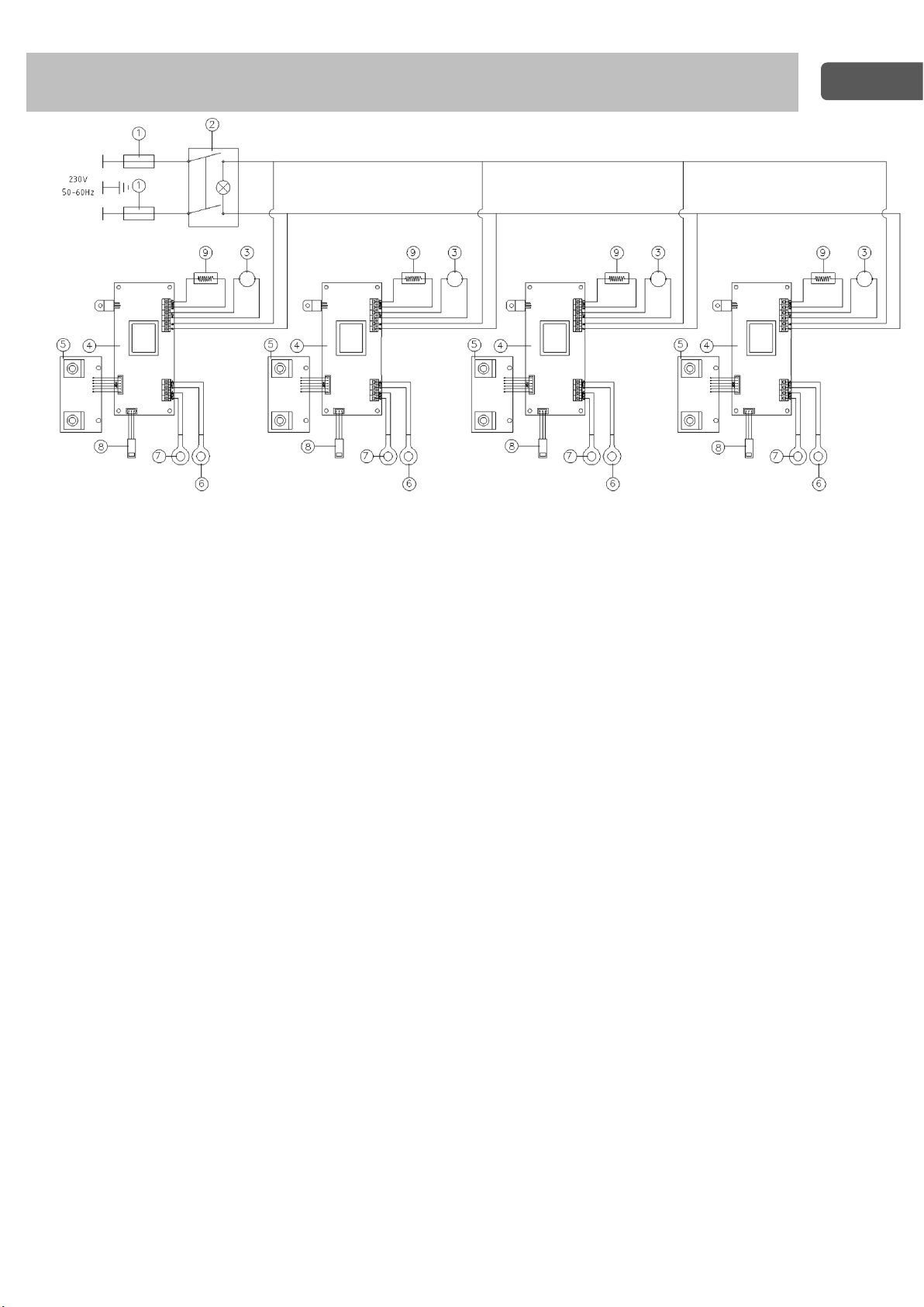
7. Wiring diagram / Schema elettrico / Schéma électrique / Esquema eléctrico /
Schaltplan / 布线图
1. Fuse / Fusibile / Fusibles / Fusible / Sicherung / 保险丝
2. ON-OFF switch / Interruttore generale / Interrupteur général / Interruptor general / Netzschalter / ON-OFF 开关
3. Electric motor / Motore elettrico / Moteur électrique / Motor eléctrico / Elektromotor / 电动机
4. Electronic board / Scheda elettronica / Fiche électronique / Tarjeta electrónica / Steckkarte / 电子板
5. Controls electronic board / Scheda controlli / Controls électronique / Ficha controles / Registerkarte Steuerelemente
/ 控制电子板
6. Safety Probe / Sonda sicurezza / sonde de sécurité/ sonda de seguridad/ Sicherheit sonde / 安全探针
7. Temperature probe / Sonda di temperatura / sonde de température / Sonda de temepratura / Temperaturfühler / 温
度探针
8. Speed sensor / Sensore velocità / Capteur de vitesse / Sensor de velocidad / Speed sensor / 速度传感器
9. Resistance / Resistenza / Résistance / Resistencia / Widerstand / 电阻
MULTI
Page 21

21
8. Declaration of conformity / Dichiarazione di conformità / Déclaration de conformité /
Declaración de conformidad / Konformitätserklärung / 符合性声明
We, the manufacturer VELP Scientifica, under our responsibility declare that the product is manufactured in conformity with
the following standards:
Noi, casa costruttrice VELP SCIENTIFICA, dichiariamo sotto la ns. responsabilità che il prodotto è conforme alle seguenti
norme:
Nous, VELP Scientifica, déclarons sous notre responsabilité que le produit est conforme aux normes suivantes:
Nosotros casa fabricante, VELP Scientifica, declaramos bajo nuestra responsabilidad que el producto es conforme con las
siguientes normas:
Der Hersteller, VELP Scientifica, erklärt unter eigener Verantwortung, dass das Gerät mit folgenden Normen übereinstimmt:
我们,制造商 VELP Scientifica,在我们的责任下声明,该产品的生产符合以下标准
EN 61010-1 EN 61326-1 2015/863/EU (RoHS III) 2012/19/EU (WEEE)
EN 61010-2-051 EN 61010-2-010
and satisfies the essential requirements of the following directives:
e soddisfa i requisiti essenziali delle direttive:
et qu’il satisfait les exigences essentielles des directives:
y cumple con los requisitos esenciales de las directivas:
und den Anforderungen folgender Richtlinien entspricht:
并满足以下指令的基本要求。
- Machinery directive 2006/42/EC / Macchine 2006/42/CE / Machines 2006/42/CE / Máquinas 2006/42/CE / Maschinen
2006/42/EG / 机械指令 2006/42/EC
- Electromagnetic compatibility directive 2014/30/EU / Compatibilità elettromagnetica 2014/30/EU / Compatibilité
électromagnétique 2014/30/EU / Compatibilidad electromagnética 2014/30/EU / Elektromagnetische Verträglichkeit
2014/30/EU / 电磁兼容性指令 2014/30/EU
- plus modifications / più modifiche / plus modifications / más sucesivas modificaciones / in der jeweils gültigen Fassung / 加
上变化.
Page 22

22
9. Declaration of conformity
We, the manufacturer VELP Scientifica, under our responsibility declare that the product is manufactured in conformity with
the following regulations:
S.I. 2016/1101
Electrical Equipment (Safety) Regulations 2016
S.I. 2016/1091
Electromagnetic Compatibility Regulations 2016
according to the relevant designated standards:
EN 61010-1
Safety requirements for electrical equipment for measurement, control, and laboratory use
Part 1: General requirements
EN 61010-2-010
Particular requirements for laboratory equipment for the heating of material
EN 61010-2-051
Particular requirements for laboratory equipment for mixing and stirring
EN 61326-1
Electrical equipment for measurement, control and laboratory use - EMC requirements -
Part 1: General requirements
and satisfies the essential requirements of regulations:
S.I. 2008/1597
Supply of Machinery (Safety) Regulations 2008
S.I. 2012/3032
Restriction of the Use of Certain Hazardous Substances in Electrical and Electronic
Equipment Regulations 2012
S.I. 2013/3113
Waste Electrical and Electronic Equipment Regulations 2013
plus modifications.
Page 23

Page 24

Thank you for having chosen VELP!
Established in 1983, VELP is today one of the world’s
leading manufacturer of analytical instruments and
laboratory equipment that has made an impact on the
world-wide market with Italian products renowned for
innovation, design and premium connectivity. VELP
works according to ISO 9001, ISO14001 and OHSAS
18001 Quality System Certification.
Our instruments are manufactured in Italy according
to the IEC 1010-1 and CE regulation.
Our product lines:
Grazie per aver scelto VELP!
Fondata nel 1983, VELP è oggi tra i leader mondiali nella
produzione di strumenti analitici e apparecchiature da
laboratorio grazie ai suoi prodotti italiani rinomati per
innovazione, design e connettività.
VELP opera secondo le norme della Certificazione del
Sistema Qualità ISO 9001, ISO14001 e OHSAS 18001.
Tutti i nostri strumenti vengono costruiti in Italia in
conformità alle norme internazionali IEC 1010-1 e alle
regole della marcatura CE.
Le nostre Linee di prodotti:
Analytical instruments
Elemental Analyzers
Digestion Units
Distillation Units
Solvent Extractors
Fiber Analyzers
Dietary Fiber Analyzers
Oxidation Stability Reactor
Consumables
Analytical Instruments
Analizzatori Elementari
Digestori e Mineralizzatori
Distillatori
Estrattori a Solventi
Estrattori di Fibra
Estrattori di Fibra Dietetica
Reattore di Ossidazione
Consumabili
Laboratory Equipment
Magnetic Stirrers
Heating Magnetic Stirrers
Heating Plates
Overhead stirrers
Vortex mixers
Homogenizers
COD Thermoreactors
BOD and Respirometers
Cooled Incubators
Flocculators
Overhead Shakers
Turbidimeter
Radiation Detector
Open Circulating Baths
Pumps
Laboratory Equipment
Agitatori Magnetici
Agitatori Magnetici Riscaldanti
Piastre Riscaldanti
Agitatori ad Asta
Agitatori Vortex
Omogeneizzatori
Termoreattori COD
BOD e Analizzatori Respirometrici
Frigotermostati e Incubatori
Flocculatori
Mescolatore Rotativo
Torbidimetro
Rilevatore di Radiazioni
Bagni Termostatici
Pompe
www.velp.com
VELP Scientifica Srl
20865 Usmate (MB) ITALY
Via Stazione, 16
Tel. +39 039 62 88 11
Fax. +39 039 62 88 120
Distributed by:
We respect the environment by printing our manuals on recycled paper.
Rispettiamo l’ambiente stampando i nostri manuali su carta riciclata.
10006408/A9
 Loading...