

Veloset VS 213, VS 2131 Installation And Operation Manual

1
W irel es s C y c le C om pu ter
Wireless Cycle Computer
INSTALLATION AND OPERATION MANUAL
I
III
II
I
I
II
213 Bracket
Computer
2131 Bracket & Sensor
213/2131 Bracket Seat
Cable Ties
Rubber slip
VS-2131
wired
VS-213
wireless
Wired Cycle Computer
VS 213
VS 2131
I NS T A L L AT IO N
P art 1 How to install the computer
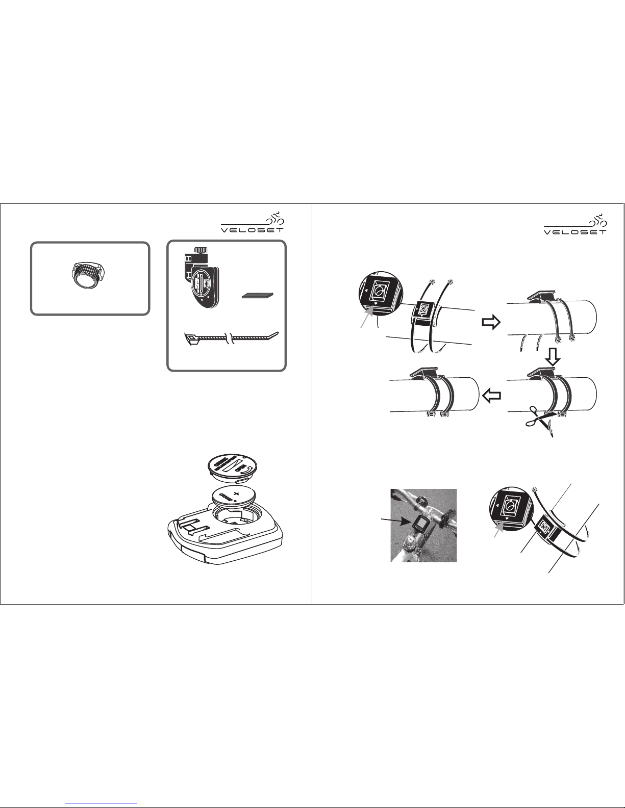
Use a coin to turn the battery
compartment anti-clockwise
to fit the CR2032 battery.
Check that the + sign is
facing upwards. Reseal and
tighten the compartment.
H o w to install the battery
(FIG B)
Installing the bracket seat
Use two cable ties to fix the bracket seat on the
bike(as Figure C)
P ar t I I ( ) Magnet
P ar t III (Wireless 213 Sender)
FIG. A
FIG. B
FIG.C
FIG.D FIG.E
2 3
Sensor
rubber s li p
(short )
Magnet
This arr ow
sign dow n
This arr ow
sign dow n
The comp ut er
can be ins ta lled
on this po si tion
The 213/2131 cycle computer can be fitted on the stem
as shown in FIG D. When fitted in this position check that
the bracket marker is facing down as shown in FIG.E
Cable ties (2 pcs)
4
FIG.E
bracket
lever
pull
in
push
out
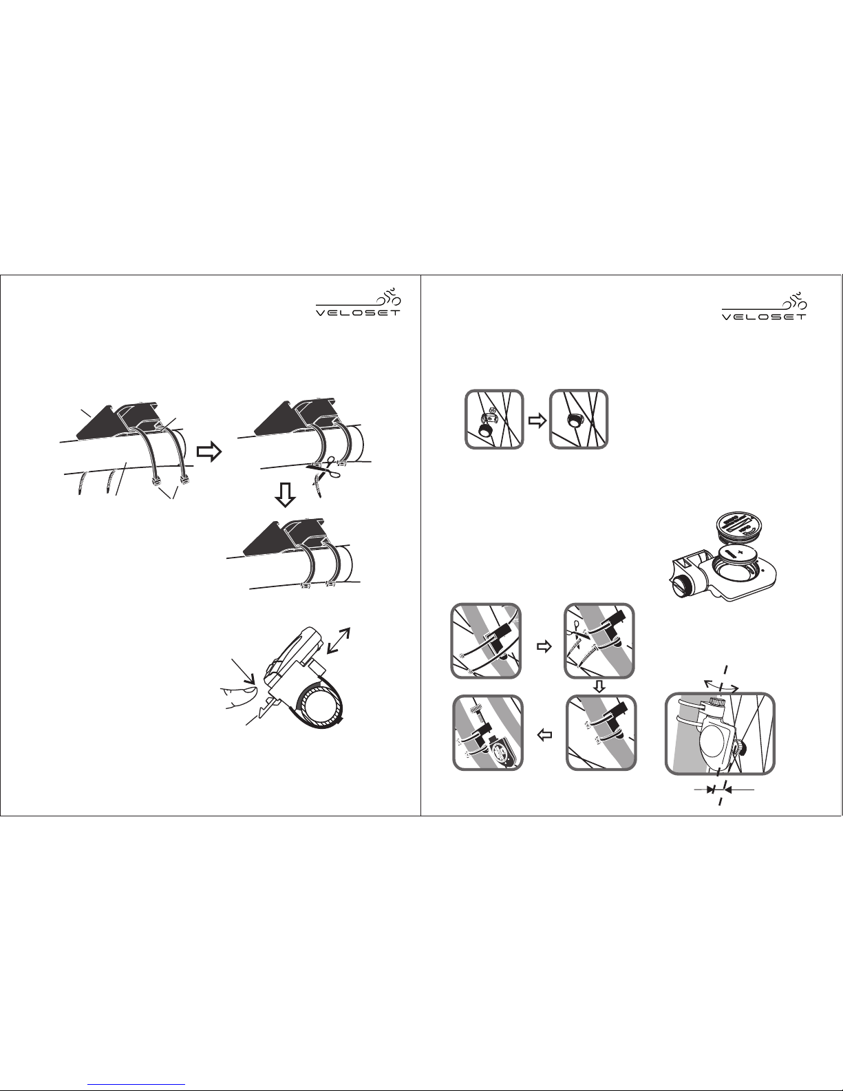
How to install the computer bracket
Add rubber slips to fix the by two
ties to the bicyc le handlebar (FIG D)
bracket
C om p u ter in s ta l l a tio n
Slide the computer into the
bracket through the slot
as F I G . E . Pr e s s th e
lightly
until the computer locks.
FIG.D
nylon
cords
computer
bracket
rubber slip
bicycle
handlebar
bracket lever down
When you want to remove
the computer from the cycle,
lightly press the bracket
lever and push the computer
out along the bracket rail.
Part II Magnet Installation
Fasten the magnet with screw to the spoke of the
wheel. (FIG.F)
5
FIG .F
FIG.G
Part III 213 Wireless Sensor Installation
Using a coin, turn the battery compartment anti-clockwise
to remove the battery cover. Insert a
CR2032 with the + facing upwards as shown
in FIG .G. Attach to the sensor to the
cycle forks using 2 cable ties as
shown in FIG.K
.
FIG. K
Angle a dju stmen t
Max5m m
The distance between the magnet
and the sensor should be within 5mm
 Loading...