


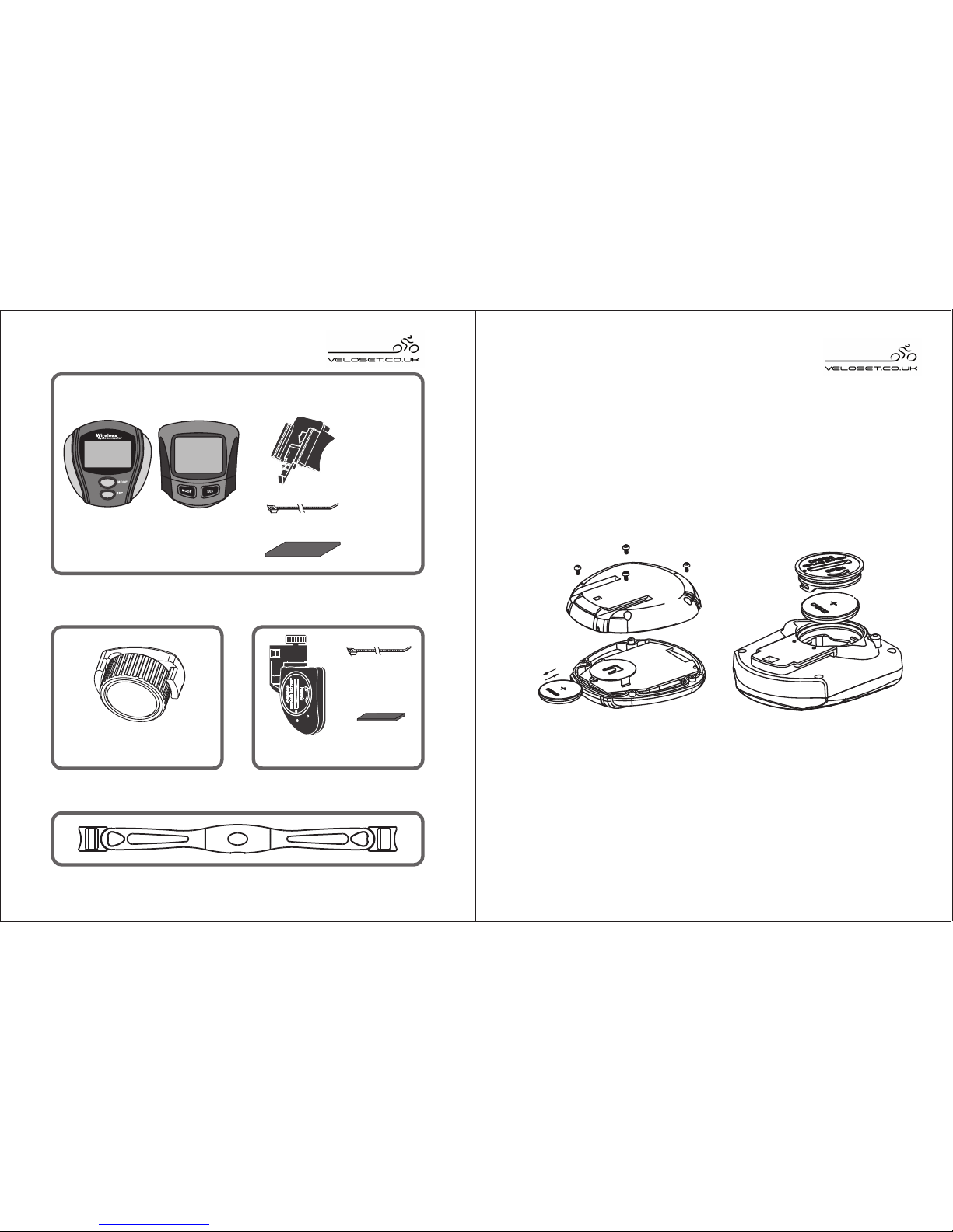
P R O DU C T G U ID E ( F IG .A )
1
W i r ele s s C y c le C omp u te r
W ire le s s c y cle c ompute r with
wireles s h ea rt ra te m onitor
W ire le s s c y cle c ompute r
VS -20 4
VS -21 2
VS -21 2 A
VS -20 4 A
FIG. A
2 3
P ar t I: R e c ei v in g Pa rts
P ar t II : M a gne t P ar t III : Tra ns m i tti n
g P
a r ts
Sensor
Rubber slip
(short)
Magnet
Bicycle computer
Nylon cord
( 2pcs)
Bracket
Accessories
P ar t IV: Ch e st B e lt (F or VS - 2 04 A / V S-21 2 A)
Rubber slip
Nylon cord
( 2pcs)
FIG.B
FIG.C
IN S T A L L AT IO N
Part 1 : How to install the computer
1.How to install the battery of VS-204 / VS-204A
2.How to install the battery of VS-212 / VS-212A
Unscrew the 4 screws on the back of the VS204 / VS204A
and place the battery + side facing upwards.(FIG B).
Replace the screws tightly to reseal the cycle computer.
Using a suitable sized coin, unscrew the battery cover
from the cycle computer, t the battery + sign facing
upwards. (FiG C) Reseal the battery compartment with
the cover and tighten.
VS-204
VS-204A
VS-212
VS-212A
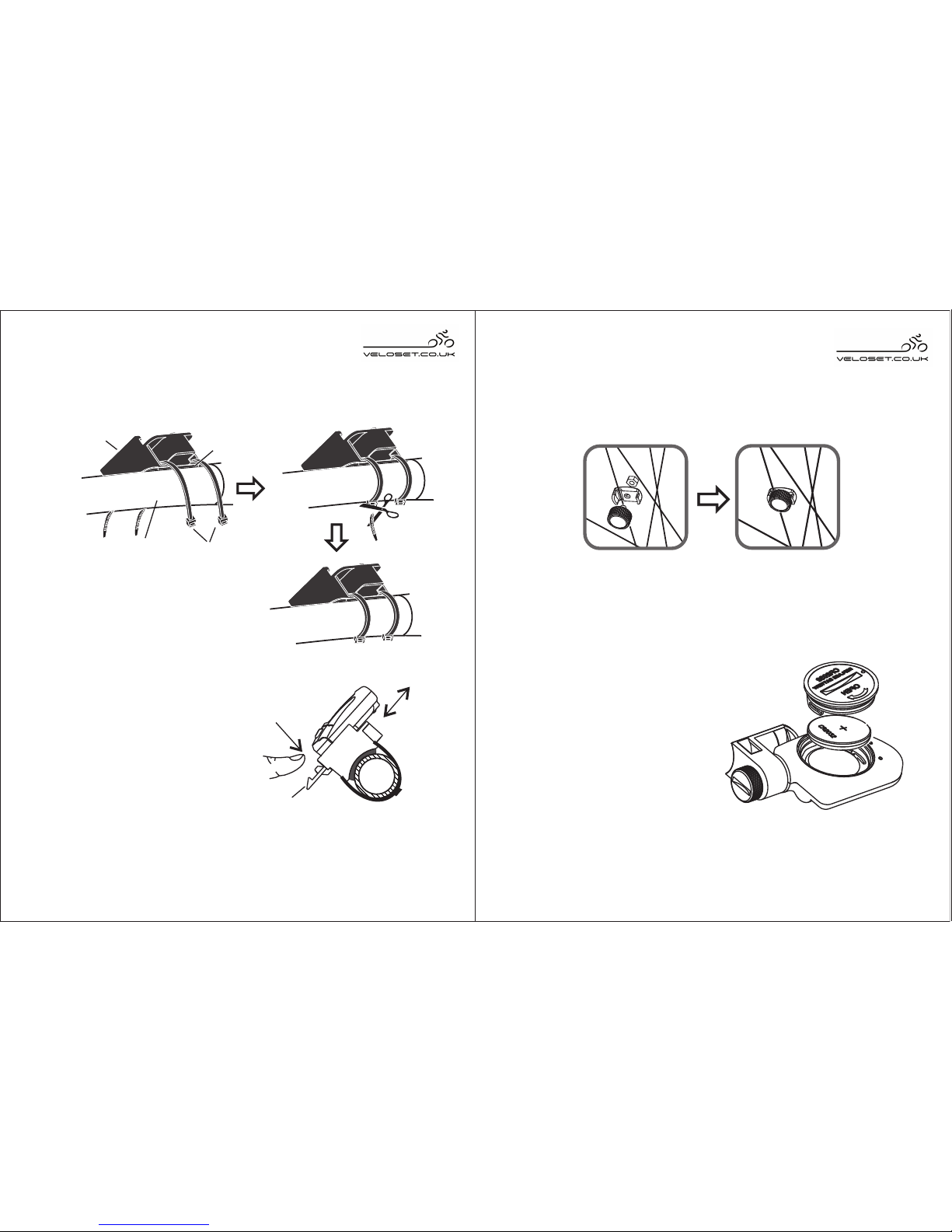
FIG.E
bracket
lever
pull
in
push
out
4
How to install the bracket
Add rubber slips to fix the by two nylon
cords to the bicyc le handlebar (FIG D)
bracket
C o m pu te r ins ta l la ti o n
Slide the computer into the
bracket through the slot
as FI G. E . Pr e ss th e
lightly
until the computer locks.
FIG.D
nylon
cords
computer
bracket
rubber slip
bicycle
Part II Magnet Installation
Fasten the magnet with screw to the spoke of the
wheel. (FIG.F)
5
FIG.F
FIG.G
Part III Sensor Installation
S ens or battery repl a c ement
Sensor replacement
Add rubber slips to fix the
sens o r by tw o ny l on
co rds to the requi red
position. (FIG.H)
handlebar
bracket lever down
When you want to remove
the computer from the cycle,
lightly press the bracket
lever and push the computer
out along the bracket rail.
Using a coin, turn the battery compartment anti-clockwise
to remove the battery cover.
Insert a CR2032 with the +
facing upwards.
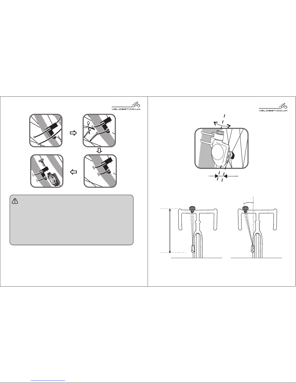
FIG. J FIG. K
6 7
Max 80 cm
Max 30°
FIG. H
N O T E:
● T he dis tanc e be twe e n magnet a nd s ens or
s hould be n o more t han 5 mm
(F ig.I) .
● The sensor should face the computer, the
dis tanc e betwe en s ens or a nd c ompute r
should be no more than 80cm (FIG.J), the
angle should be no more than 30 °(FIG.K).
FIG. I
Angle adjustment
Max5mm

F U N C T IO N S
Please test the computer to see if it works well after
installation. If necessary, adjust the position or angle of
the computer and sensor..
Battery installati on and replacement (Fig. L)
8
FIG.L
conductive pad
conductive pad
VS -21 2 VS -2 1 2 AVS -20 4
DST
Display
VS -20 4 A
Distance
SPD
Functions
√
√
√
√
√
√
√
√
√
√
√
√
Clock
Speed
9
B U T T O N S
1.MODE
RTM
√
×
×
√
√
√
√
√
√
√
√
×
√
√
√
√
√
√
√
×
×
√
√
√
√
√
√
√
√
×
√
√
√
√
√
√
√
√
√
×
√
TEMP
AVS
RES
PULS E
MXS
ODO
√√√√
Riding time
Average speed
Relative speed
Max. speed
ODO
Scan
Auto-off
Dynamic speed
Pulse
Anti-interference
Backlight
Temperature
√√√
VS -21 2 VS -2 1 2 AVS - 2 0 4
Display
VS -20 4 A
Functions
NOTE: ”means with this function, means without “√ “×”
Replacing the battery of the Wireless heart rate
Chest belt.
Pressing the Mode button will change the display to show.
Speed/Clock/Distance/Riding time/Temperature/Pulse/
Average Speed/Maximum Speed/Odometer/Scan Mode.

Circumference = Diam eter x 25.4 x 3.1416
2.Wheel size in MM
Circumference = Diam eter x 3.1416
2.SET
1) RESET: Reset Distance/Riding time/ Average
speed/Max.speed
2) To s e t v al u es : In SET mode, press this
button to set values.
3.Back light(VS-212)
1.Wheel size in INCH
10 11
FIG.M
Back light
16X1.75X2
20X1.75X2
24X1 3/8 A
24X1.75X2
26X1
26X1.5
26X1.6
26X1.75X2
26X1.9
26X2.00
26X2.125
26X1 3/8
47-305
47-406
37-540
47-507
23-571
40-559
44-559
47-559
50-559
54-559
57-559
37-590
1272
1590
1948
1907
1973
2026
2051
2072
2089
2114
2133
2105
Wheel Cir .( mm )
Dim e ns ion m ar k ed in the whee l
2) Setting the Function of : Metric system /
Imperial system, wheel circumference, clock setting
The back light button is positioned on
theback of the VS-212 computer. When
pressed the backlight will display for a
short time (5 seconds).
How to measure the wheel circumference
First Method :
Use a tape measure to nd the diameter of the front
bike wheel (Calculation 1), or you can calculate the
wheel circumference according to the wheel / tyre size.
(Calculation 2).
Second Method:
Refer to the table below and locate the wheel circumference
according to the dimensions marked on the wheel.

Wheel Cir .( mm )
26X1 3/8X1 1/2
26X3/4
27X1 1/4
27X1 1/4 Fifty
28X1.5
28X1.75
28X1 1/2
28X1 3/8X1 5/8
700X1 8C
700X20C
700X23C
700X25C
700X28C
700X32C
700X35C
700X40C
20-571
32-630
28-630
40-622
47-622
40-635
37-622
18-622
20-622
23-622
25-622
28-622
32-622
37-622
40-622
37-584
1954
2199
2174
2224
2268
2265
2205
2102
2114
2133
2146
2149
2174
2205
2224
2086
Dim e ns ion m ar k ed in the whee l
12 13
Third Method : Measure the Wheel circumference as
shown in FIG.N
1.
2.Press and hold SET, switch bet ween "KM/H"
and "M/H".Press MODE to confirm and exi t.
Then proceed to bike cir cumference se tting.
3."2074" will display and the last fig ure "4" wil l
flash, p ress SET to select value and press
MODE t o conf irm and exit. Then proce ed to
next f igure setting, do th e same as above. After
finish all fig ure se tting, press MODE to confirm
and proceed to CLOCK set ting.
FIG.N
CIRCUMFERENCE
Setting the Speed unit, Wheel circumference
and Clock.
To enter into Set up mode, replace the battery or press
SET and MODE together for 3 seconds. The display will
return to show KM/H ashing as the rst setting to change.

14
HOW TO USE THE BICYCLE COMPUTER
1.Reset previous values to zero before each
FIG.O
SET+ MO DE
2S
MODE f or c hanging
from l ow t o high
MODE f or c ha nging
from h ou r to minute
KM/H
MODE MODE
MODE MODE
KM/H
2074
KM/H
SPD
KM/H
KM/H
Set sp ee d unit Set circu mf er ence
12Hr /2 4Hr
Set cl oc k
4.Do the same as above, press SET to sel ect
value and pres s MODE to confirm and proceed
to next. (FIG.O)
No te: T he b ike c ircumference unit is mm.
W hen in 12H format, P M is displayed
measurement. When the speed is zero (except
SCAN mode), hold SET for 2 seconds to reset the
value of DST(d i s t a n c e ) , RTM (riding time),
AVS (average speed) , RE S (rel a t i v e speed) and
MXS(max. speed)
2.The measurement begins once riding on the
bicycle. If the computer receive no signal during
riding, the " " in the display will not flash. Stop
riding and check if the magnet is positioned
3.Press MODE to select the preferred display or select the
SCAN mode. When in SCAN mode the display will
change between all functions every 4 seconds.
4.The computer will turn off automatically if there is
no operation or signal for 8 minut
es, the data for the
jouney will be saved. Y
ou can press any button to
turn on the computer to receive the signal again.
H O W T O W E A R T H E C H E S T B E L T
(F O R MO DE L V S-2 04 A /VS -2 12 A )
1.Wet the conductive pads on the underside
of
the transmitter with water or conductive gel to
15
When the computer has been installed and the wheel
size has been programmed into the computer, you are
ready to use the cycle computer:
correctly
for afternoon.
In order to get correct heart rate signals, you need to ensure
that the chest belt is worn correctly. (FIG.O) The chest belt
will transmit the data wirelessly to the cycle computer.

FIG.Q
17
computer) will start transmitting and receivin g
signal once batteries are in place. Both units
should be worn or mounted withi n an effect ive
distance of 80 c entimeters (31inches). If the
A. Shorten the distance between the transmitter
and receiver.
B. Re-adjust the position of the transmitter.
C. Check the batteries. Replace them when necessary.
H E A R T R AT E ME A S U R E ME N T (F O R
MO DE L V S -2 04 A /VS -2 12 A )
Press MODE to pulse display, the“ ” will flash in
the right corner of the LCD.
Th e c omputer is now
r e c e i
v i n g t h e p u l s e
signal and will show your
heart rate value in a
short time, see FIG.Q.
N o te :
●
If you wear a heart pace maker, please do
FIG.P
ensure a solid contact.
2.Strap the belt across the chest. Adjust the strap until
the conductive pads sits snugly below the pectoral
muscles for an accurate heart rate signal.
H i nt s : T he pos ition of the tra ns mitter a ffe cts
i t s p e r f o r m a n c e . M o v e t h e
tra ns mitte r a long the s tra p for the
be st tra ns mis s ion. Avoid a re a s with
de ns e c he s t ha ir.
In dry, cold c lima te s, it ta k es the
tr a ns m i tte r a w hil e t o f unc ti on
s te a di l y. T hi s is n or ma l a s th e
conduc tive pa ds ne e d a film of s we at
to i mpr ove c onta ct with the s k in.
E F F E C TIV E RANG E
The transmitter in the s trap and re ceiver(bicy cle
16
the signal is lost, perform the following:
not use the heart rate monitoring chest belt.

H O W T O R E A D E A C H D IS P L AY
1.As sh own in FIG. R:
i. U pp e r li n e sh o ws
t h a t y o u r c u r r e n t
r i d i n g s p e e d i s
20.2km/h.
ii.KM means you a re
in met ric syst em and
all the s p e e d and
d i s t a nc e w i ll b e
represented in metri c.
iii.Lower line shows t he clock.
iv.Icon "▲ " or "▼ " fla shing sh ows that your
current speed is higher or lower than the
average spe ed.
v." " flashing means the computer is receiving the
2.Press MODE and switch to the display as FIG.S:
i.Upper line s hows that your curren t riding
speed is 20.2km/h.
ii.Lower line sh
ows that your riding distance
is 5.6 Kilometres
3.P r e ss MOD E again
a n d s w i t c h t o t h e
display as FIG.T:
i. U p per l ine s how s
yo u r curre nt ridi ng
speed.
ii.Lower line shows
your riding time.
iii.It will stop counting
automatically if th ere
is no si gnal received
over 6 seconds.
4 . P r e s s M O D E a n d
switch to the display as
FIG.U. The upper line
sho w s yo u r cur r ent
speed, and the lower line shows your current
pulse rate. (VS-204A/VS-212A)
5.Pr e s s M O DE a gain
a n d s w i t c h t o t h e
d
isplay as FIG.V:
I. U p p e r l i n e s h o w s
y o u r c u r r e n t r i d i n g
speed.
ii.Lower line shows that
the temperature wher e
19
FIG.R
KM/H
SPD
18
FIG.S
FIG.T
FIG.U
KM/H
SPD
DST
KM/H
SPD
RTM
Note: Do not use the heart monitoring chest belt near a computer,
wireless router, mobile or any appliance emmitting an
electromagnetic wireless signal. This will cause interference and
inaccurate measurements could occur.
signal correctly.

you are is 24°C.
iii.Press SET to see the
temperature in °F.
6.Press MODE a gain and
switch to the display as
FIG.W:
i. D y n a m i c s p e e d
indicator shows the in stantaneous speed
ii
.
AV
S shows the average spee d from exer cise
start to where you are is 10 .2km/h.
i i i . L o w e r l i n e R E S
s h o ws t h e r el a t i ve
s p e e d b e t w e e n
av e r age s p eed a n d
ins t a ntaneous speed
is 10.0km/h. In that
c a s e, y o u r c u r r e n t
s p e e d i s f a s t e r
1 0 . 0 k m / h t h a n t h e
average spe ed. If the in stantan eous speed is
lo wer
th an average speed, RES will show
minus. (JS-204/JS- 212)
N ote : A fte r cy c ling for more th a n 9H 59 M5 9 S
(the m ax t ime f or m e mory ) , the a ve r a ge s pe ed
KM/H
SPD
TEMP
20
FIG.W
FIG.V
will dis pla y inc orr e ctly. P le a s e c le ar b o th
ex e rc is e time a nd dis tance to z e ro to get a
corre ct v a l u e of the avera ge spe e d.
7.Press MODE a gain and switch t o the display as
FIG.X :
i.MXS show s the fastest speed during riding is
30.5km/h.
ii.ODO shows the total
distance from replacing
the battery.
iii.The ODO val ue can
not b e reset to zero by
pr e ssing SET butt on,
instead hold MODE and
SET buttons at the same time
for 2 seconds.
■ N OT E
1.The bicycle compute r is water-r e s i s t a nt
and can be used in light rain showers.
2.The bat tery for th e sensor and c
omputer c an be
used for 1 year if used for 2 hours each day. It is
21
FIG.X

22 23
necessary to replace battery when the recei ved
3.The max imum space between bicycle computer
and sensor should be 90cm, and the angle should
not be over 30°. The distance between magnet
and sensor should be no more than 5 m m.
4.Avoid draining the battery when you are not using the
com p uter, it is rec o mmended to kee p the
magnet away from the sen sor.
5.Please do not use the product near a microwave
oven, TV, computer, mobile phone or any other
wireless device. The electromagnetic interference
from some devices can cause an inaccurate read out.
■ Trouble-shooting Guide
P ro b le m
C au s e S o l uti o n
P ro b le m
C au s e S o l uti o n
Re-install the computer
Re-install the battery
correctly or replace the
battery
No power in sensor
or computer
The computer
can not receive
any signal
Display inaccurate
speed and distance
Incorrect setting of
wheel circumference
Re-set the circumference
away from that
interfering signal
Faulty speed
display
other strong signals
interfering
The chest belt is
too far from the
computer.
Incorrect wear of
chest belt
No power of chest
belt
Keep the distance between
the chest belt and computer
within 80cm.
Wear the chest belt as per
Replace the battery
No heart rate value
display when
monitor heart rate
Incorrect computer
installation position
signal is showing signs of loss.
For more information on Veloset products, support and distributors
please contact us at support@veloset.co.uk You can nd us on
Twitter, Facebook and our website at www.veloset.co.uk
Veloset Cycle Computers
PoBox 326
Manchester
England
M28 2YW
the instruction manual
 Loading...