

Veloset VS-204, VS-212, VS-204A, VS-212A Product Manual

P R O DU C T G U ID E ( F IG .A )
1
W i r ele s s C y c le C omp u te r
W ire le s s c y cle c ompute r with
wireles s h ea rt ra te m onitor
W ire le s s c y cle c ompute r
VS -20 4
VS -21 2
VS -21 2 A
VS -20 4 A
FIG. A
2 3
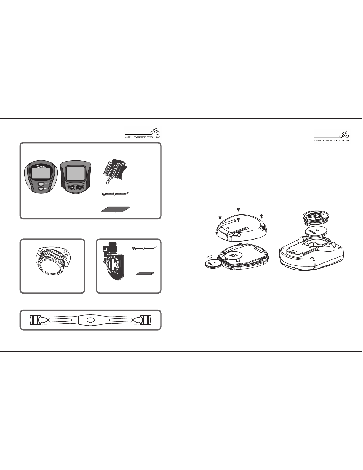
P ar t I: R e c ei v in g Pa rts
P ar t II : M a gne t P ar t III : Tra ns m i tti n
g P
a r ts
Sensor
Rubber slip
(short)
Magnet
Bicycle computer
Nylon cord
( 2pcs)
Bracket
Accessories
P ar t IV: Ch e st B e lt (F or VS - 2 04 A / V S-21 2 A)
Rubber slip
Nylon cord
( 2pcs)
FIG.B
FIG.C
IN S T A L L AT IO N
Part 1 : How to install the computer
1.How to install the battery of VS-204 / VS-204A
2.How to install the battery of VS-212 / VS-212A
Unscrew the 4 screws on the back of the VS204 / VS204A
and place the battery + side facing upwards.(FIG B).
Replace the screws tightly to reseal the cycle computer.
Using a suitable sized coin, unscrew the battery cover
from the cycle computer, t the battery + sign facing
upwards. (FiG C) Reseal the battery compartment with
the cover and tighten.
VS-204
VS-204A
VS-212
VS-212A
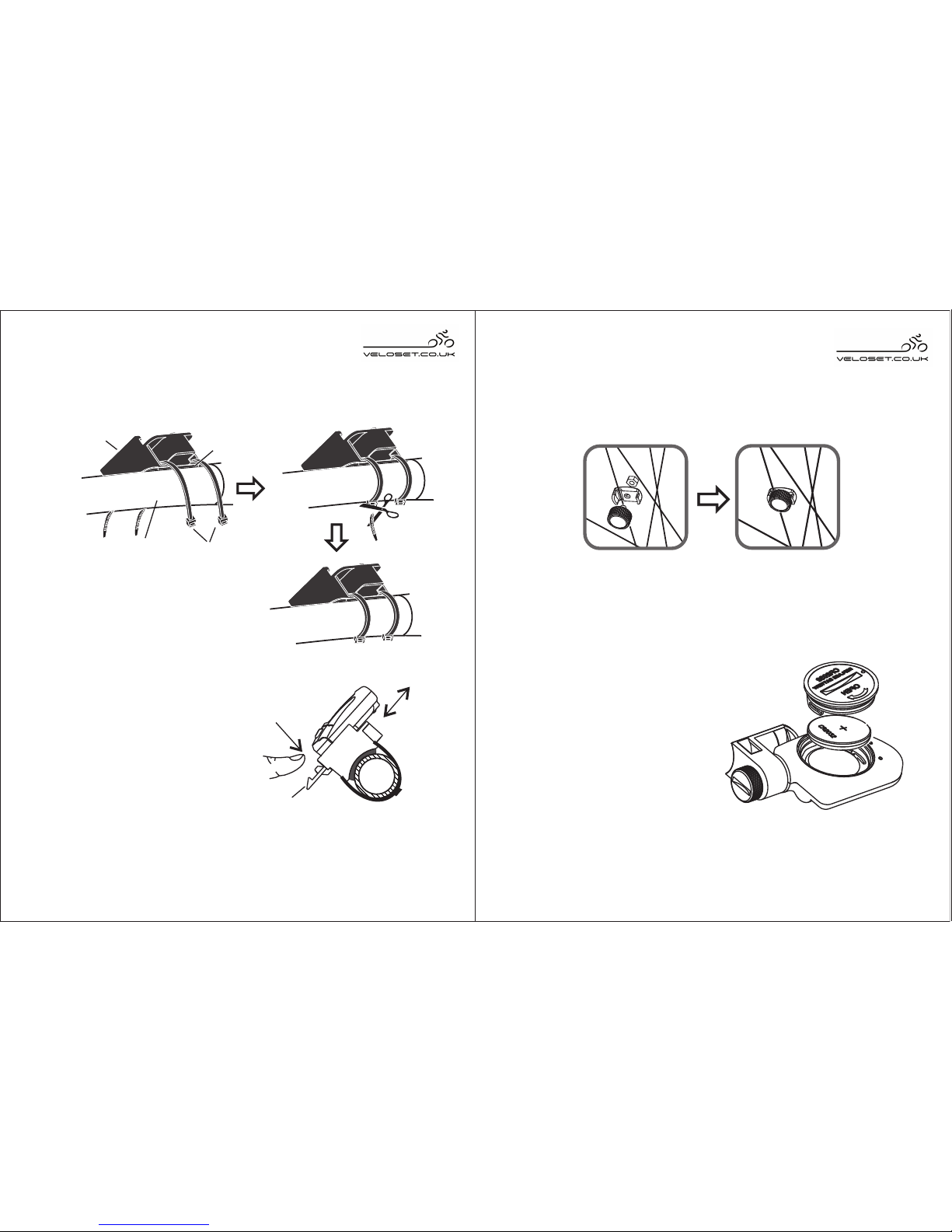
FIG.E
bracket
lever
pull
in
push
out
4
How to install the bracket
Add rubber slips to fix the by two nylon
cords to the bicyc le handlebar (FIG D)
bracket
C o m pu te r ins ta l la ti o n
Slide the computer into the
bracket through the slot
as FI G. E . Pr e ss th e
lightly
until the computer locks.
FIG.D
nylon
cords
computer
bracket
rubber slip
bicycle
Part II Magnet Installation
Fasten the magnet with screw to the spoke of the
wheel. (FIG.F)
5
FIG.F
FIG.G
Part III Sensor Installation
S ens or battery repl a c ement
Sensor replacement
Add rubber slips to fix the
sens o r by tw o ny l on
co rds to the requi red
position. (FIG.H)
handlebar
bracket lever down
When you want to remove
the computer from the cycle,
lightly press the bracket
lever and push the computer
out along the bracket rail.
Using a coin, turn the battery compartment anti-clockwise
to remove the battery cover.
Insert a CR2032 with the +
facing upwards.
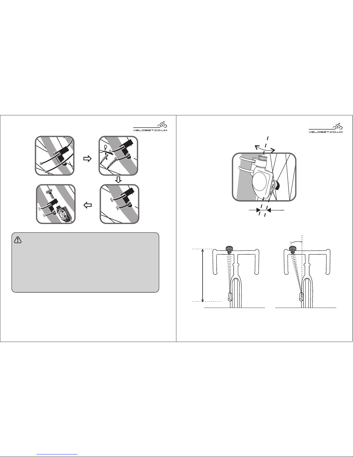
FIG. J FIG. K
6 7
Max 80 cm
Max 30°
FIG. H
N O T E:
● T he dis tanc e be twe e n magnet a nd s ens or
s hould be n o more t han 5 mm
(F ig.I) .
● The sensor should face the computer, the
dis tanc e betwe en s ens or a nd c ompute r
should be no more than 80cm (FIG.J), the
angle should be no more than 30 °(FIG.K).
FIG. I
Angle adjustment
Max5mm
 Loading...