

Veloset JS-204, JS-204A, JS-212A, JS-212 Instruction Manual

Remark: This unit just be used as normal sporting
exercise, can't be used as medical
indicator.
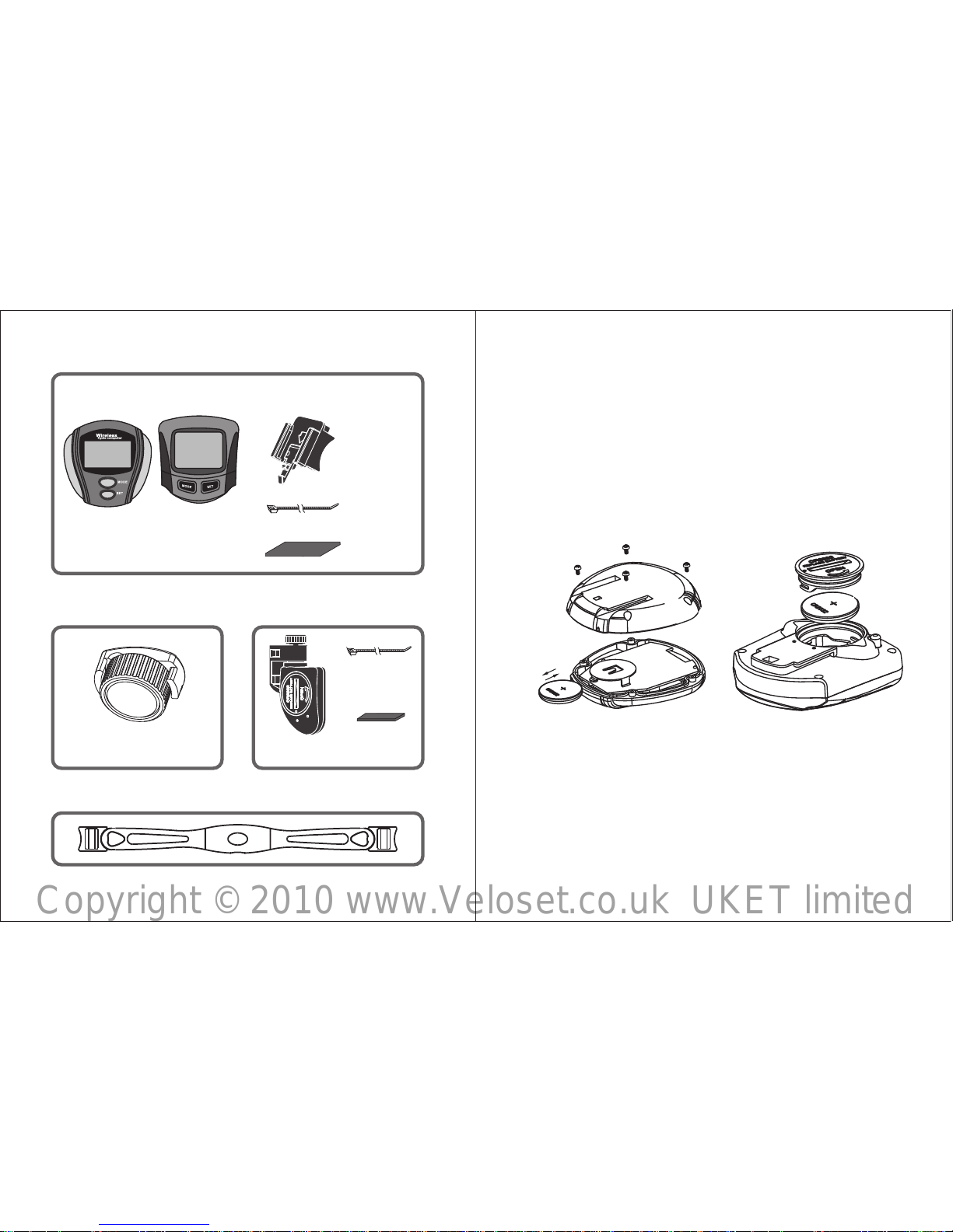
¢PRODUCT GUIDE (FIG.A)
1
Wireless Cycle Computer
Wireless cycle computer with
wire less heart rate monitor
Wireless cycle computer
JS-204
JS-212
JS-212A
JS-204A
FIG. A
Copyright © 2010 www.Veloset.co.uk UKET limited
2 3
3DUW,3DUWV
3DUW,0DJQHW
Part III: Transmitting Parts
Sensor
rubber slip
(short)
Magnet
VS- 212
VS- 212A
VS- 204
VS- 204A
Bicycle computer
nylon cord
(2pcs)
Bracket
Accessories
Part IV: Chest Belt(For J S- 20 4A/JS-212A)
rubber slip
nylon cord
(2pcs)
FIG.B
FIG.C
¢INSTALLATION
Part I How to install the computer
¥How to install the battery of computer
1.How to install the battery of 9S-204/9S-204A
Wrest the 4 screws on the back of computer, remove
the back case and put the battery as the Fig.B. Seal
the back case, and install the screws tightly.
2.How to install the battery of JS-212/JS-212A
Using a coin or other tools to loose the battery cover,
put the battery as the Fig.C. Then close the cover.
Copyright © 2010 www.Veloset.co.uk UKET limited
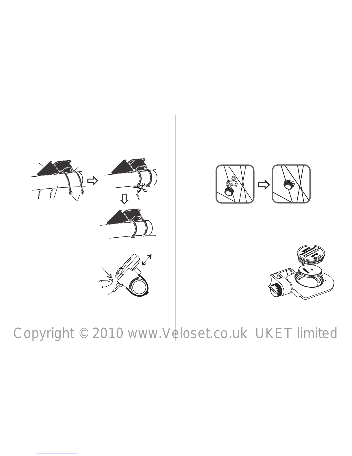
FIG.E
buc kle
hand le
pull
in
push
out
4
¥How to install the bracket
Add rubber slips to fix the by two nylon
cords to the bicycle gripe. (FIG.D)
bracket
¥Comput er installation
Slide the computer into
bracket through the slot
as F I G . E . Pre s s the
handle of buckle tightly
until the computer won't
pull off. When you want
to remove the computer
out of bracket, just press
the handle of buckle and
push the computer out
through the slot.
FIG.D
nylon
cords
comp uter
brac ket
rubb er slip
bicy cle
grip e
Part III Magnet installation
Fasten the magnet with screw to the spoke of the
whee l. (FIG.F)
5
FIG.F
FIG.G
Part II SENSOR INSTALLATION
Sensor battery replacement
Wrest the 4 screws on the back of sensor, remove the
back case and put(or
replace) a battery A23
12V. Seal the back case,
and install screws tightly.
(FIG.G)
Sensor replacement
Add rubber slips to fix the
sens o r by two n y lon
co rds t o the requ ired
position. (FIG.H)
Copyright © 2010 www.Veloset.co.uk UKET limited
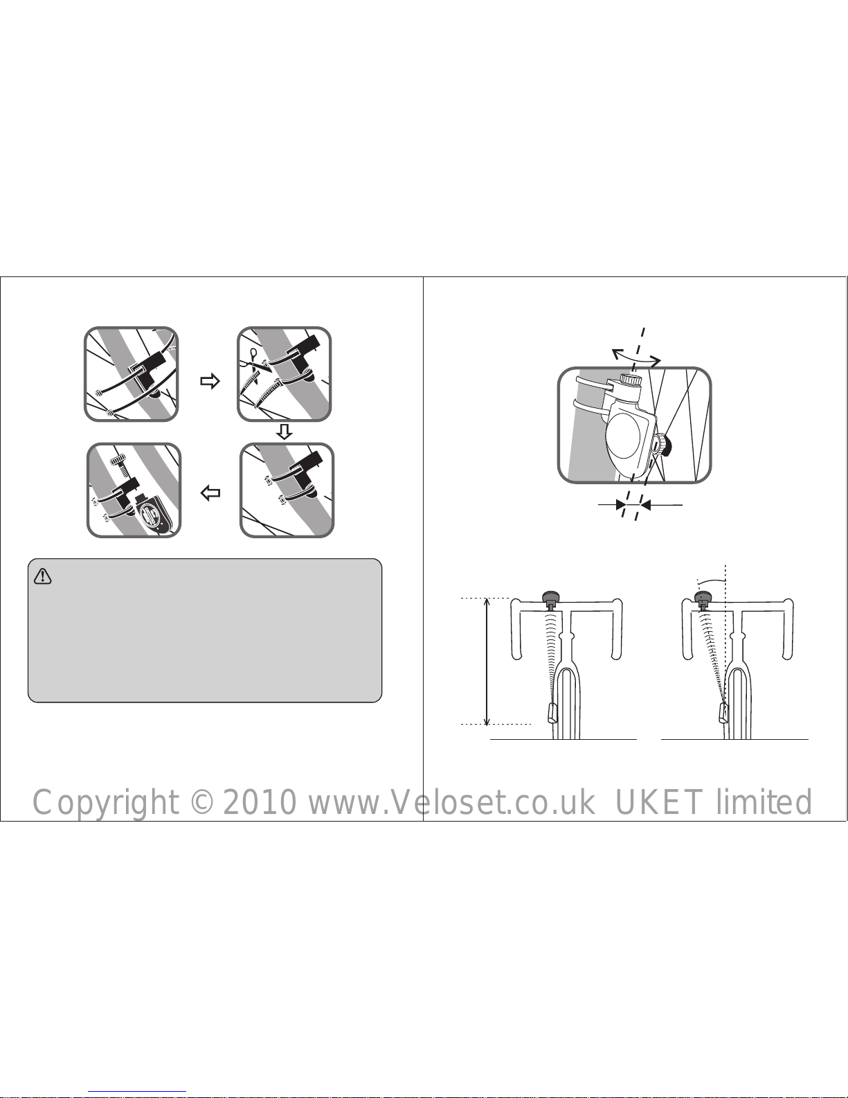
FIG. J FIG. K
6 7
Max 80cm
Max 30°
FIG. H
NOTE:
● The distance between magnet and sensor
should be no more than 5mm (Fig.I).
● The sensor should face the computer, the
distance between sensor and computer
shoubld be no more than 80cm (FIG.J), the
angle should be no more than 30°(FIG.K).
FIG. I
Angle adjustment
Max5mm
Copyright © 2010 www.Veloset.co.uk UKET limited
 Loading...