

Remark: This unit just be used as normal sporting
exercise, can't be used as medical
indicator.
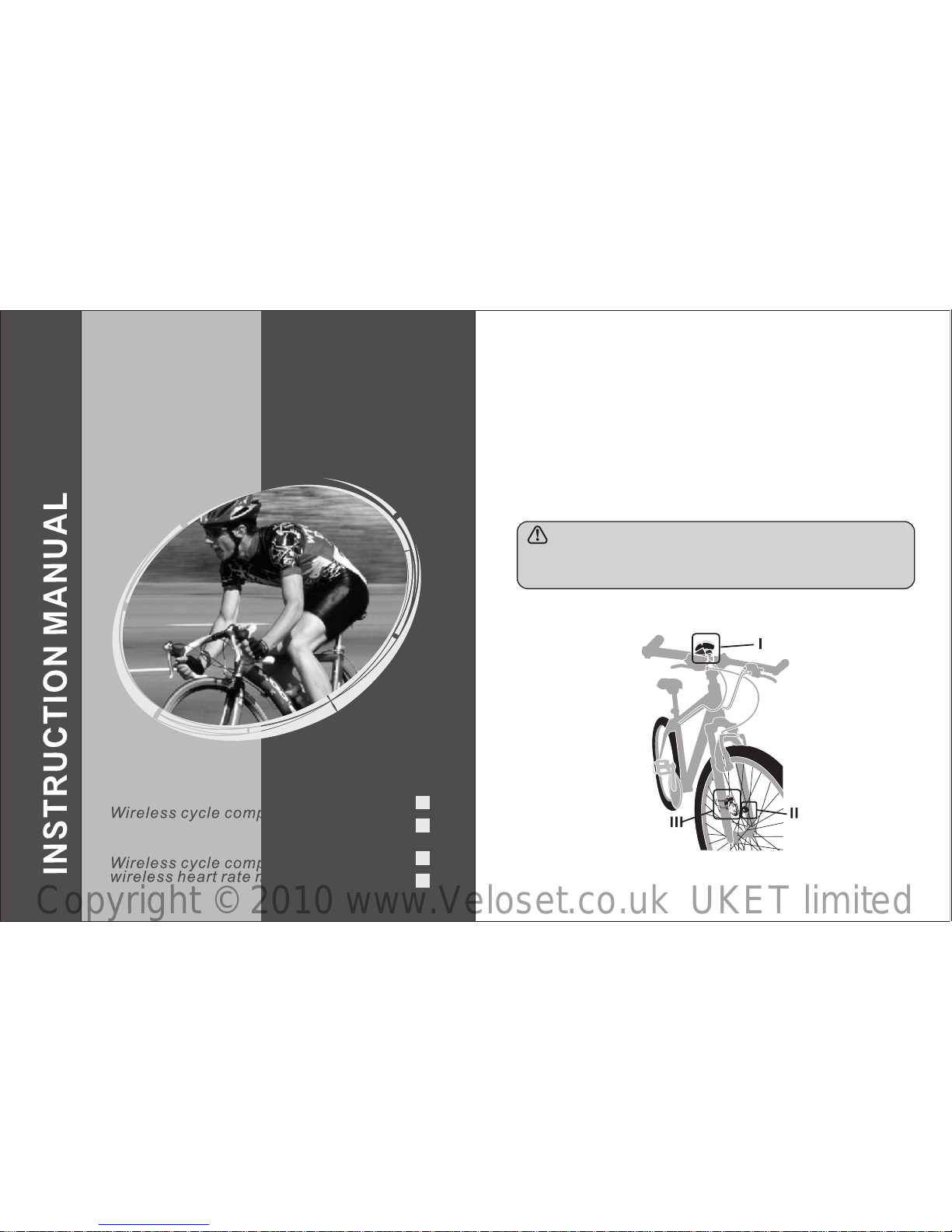
¢PRODUCT GUIDE (FIG.A)
1
Wireless Cycle Computer
Wireless cycle computer with
wire less heart rate monitor
Wireless cycle computer
JS-204
JS-212
JS-212A
JS-204A
FIG. A
Copyright © 2010 www.Veloset.co.uk UKET limited
2 3
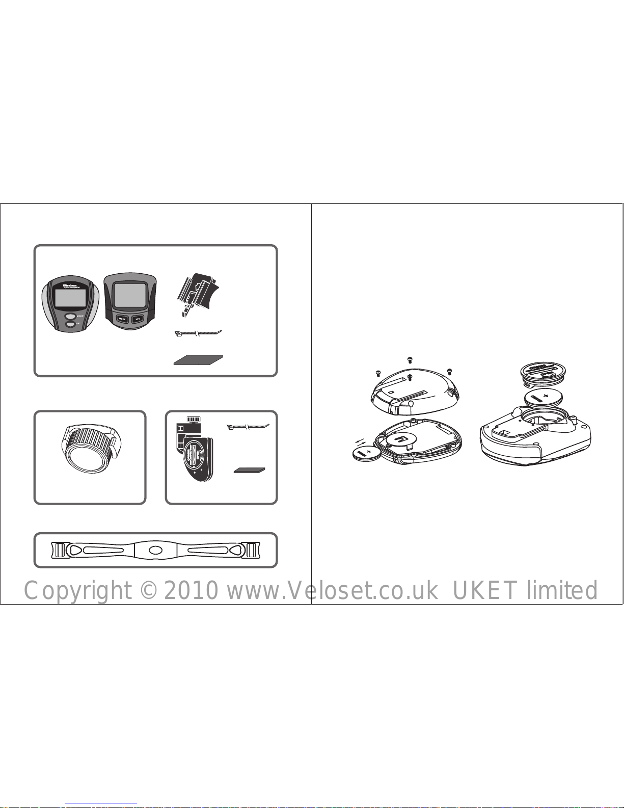
3DUW,3DUWV
3DUW,0DJQHW
Part III: Transmitting Parts
Sensor
rubber slip
(short)
Magnet
VS- 212
VS- 212A
VS- 204
VS- 204A
Bicycle computer
nylon cord
(2pcs)
Bracket
Accessories
Part IV: Chest Belt(For J S- 20 4A/JS-212A)
rubber slip
nylon cord
(2pcs)
FIG.B
FIG.C
¢INSTALLATION
Part I How to install the computer
¥How to install the battery of computer
1.How to install the battery of 9S-204/9S-204A
Wrest the 4 screws on the back of computer, remove
the back case and put the battery as the Fig.B. Seal
the back case, and install the screws tightly.
2.How to install the battery of JS-212/JS-212A
Using a coin or other tools to loose the battery cover,
put the battery as the Fig.C. Then close the cover.
Copyright © 2010 www.Veloset.co.uk UKET limited
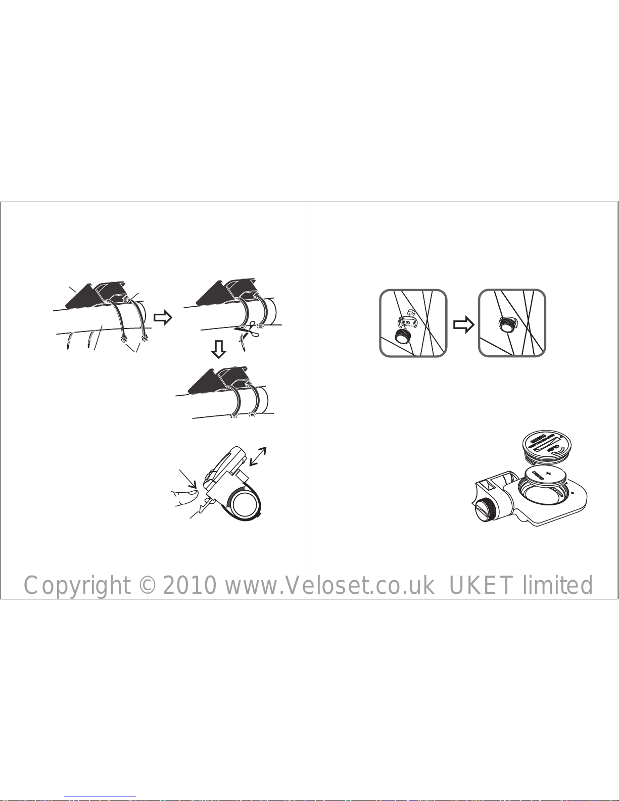
FIG.E
buc kle
hand le
pull
in
push
out
4
¥How to install the bracket
Add rubber slips to fix the by two nylon
cords to the bicycle gripe. (FIG.D)
bracket
¥Comput er installation
Slide the computer into
bracket through the slot
as F I G . E . Pre s s the
handle of buckle tightly
until the computer won't
pull off. When you want
to remove the computer
out of bracket, just press
the handle of buckle and
push the computer out
through the slot.
FIG.D
nylon
cords
comp uter
brac ket
rubb er slip
bicy cle
grip e
Part III Magnet installation
Fasten the magnet with screw to the spoke of the
whee l. (FIG.F)
5
FIG.F
FIG.G
Part II SENSOR INSTALLATION
Sensor battery replacement
Wrest the 4 screws on the back of sensor, remove the
back case and put(or
replace) a battery A23
12V. Seal the back case,
and install screws tightly.
(FIG.G)
Sensor replacement
Add rubber slips to fix the
sens o r by two n y lon
co rds t o the requ ired
position. (FIG.H)
Copyright © 2010 www.Veloset.co.uk UKET limited
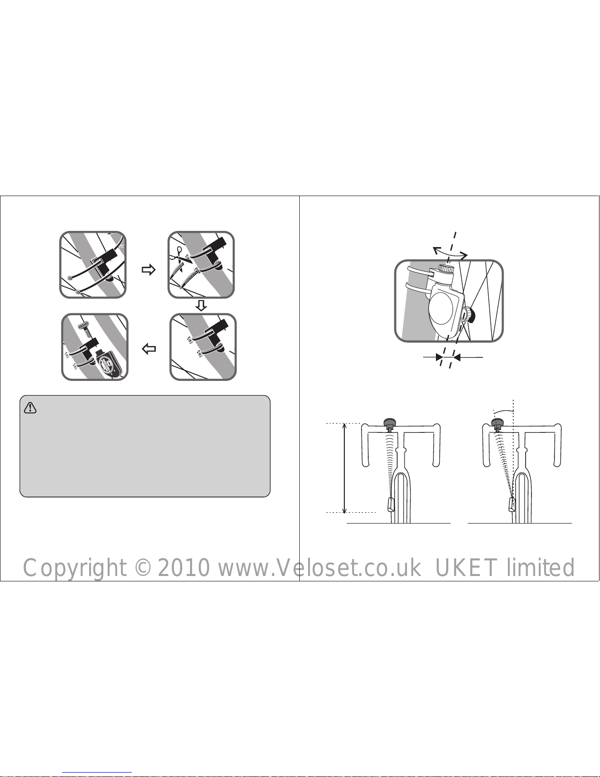
FIG. J FIG. K
6 7
Max 80cm
Max 30°
FIG. H
NOTE:
● The distance between magnet and sensor
should be no more than 5mm (Fig.I).
● The sensor should face the computer, the
distance between sensor and computer
shoubld be no more than 80cm (FIG.J), the
angle should be no more than 30°(FIG.K).
FIG. I
Angle adjustment
Max5mm
Copyright © 2010 www.Veloset.co.uk UKET limited

¢FUNCTIONS
Please test the computer to see if it works well after
installation. If necessary, adjust the position or angle of
the computer and senor.
HOW TO INSTALL AND REPLACE THE
BELT BATTERY ( FOR MODEL JS-204A/
JS-212A)
Batter y installation and replac ement (Fig.L)
¢
8
FIG.L
conductive pad
conductive pad
JS-212 JS-212AJS-204
DST
Display
JS-204A
Distance
SPD
Functions
√
√
√
√
√
√
√
√
√
√
√
√
Clock
Speed
9
¢BUTTONS
1.MODE
1)Func tions switch:Speed/Cloc k/Distance/Ridind
t ime/ Tempera ture/Pulse/Average speed/
Max.sp eed/ ODO/ Scan
RTM
√
×
×
√
√
√
√
√
√
√
√
×
√
√
√
√
√
√
√
×
×
√
√
√
√
√
√
√
√
×
√
√
√
√
√
√
√
√
√
×
√
TEMP
AVS
RES
PULSE
MXS
ODO
√√√√
Riding time
Average speed
Relative speed
Max. speed
ODO
Scan
Auto-off
Dynamic speed
Pulse
Anti-interference
Backlight
Temperature
√√√
JS-212 JS-212AJS-204
Display
JS-204A
Functions
NOTE: ”means with this function, means without
this function.
“√ “×”
Copyright © 2010 www.Veloset.co.uk UKET limited

Circ umference = Diameter x 25.4 x 3.1 416
2.Whee l size in MM
Circ umference = Diameter x 3.1416
Second method: Refer to the below data according
to the dimension marked in the
wheel.
2) Funct ion con firma tion: metric system/
i m p e r i a l s y s t e m , w h e e l
circ umference size, clock setti ng
2.SET
1)RESET: Reset Distance/Riding time/ Average
speed/Max.speed
2)To se t values: In S ET mode, press this
button t o set values.
3.Back l ight(JS-212)
The ba ck light button is in
the case bac k. It will light
for ar ound 5 seconds by
ever y pressing. (FIG.M)
HOW TO MEASURE THE BIKE
CIRCUMFERENCE
Use tapeline to measure the diameter of front
bike wheel. Or, you can c alculate the bike
circ umference accordi ng t o the wheel si ze
mark ed in bike instruction manual .
1.Whee l size in INCH
¢
10 11
FIG.M
Back light
16X1.75X2
20X1.75X2
24X1 3/8 A
24X1.75X2
26X1
26X1.5
26X1.6
26X1.75X2
26X1.9
26X2.00
26X2.125
26X1 3/8
47-305
47-406
37-540
47-507
23-571
40-559
44-559
47-559
50-559
54-559
57-559
37-590
1272
1590
1948
1907
1973
2026
2051
2072
2089
2114
2133
2105
Wheel Cir.(mm)
Dimension marked in the wheel
Copyright © 2010 www.Veloset.co.uk UKET limited

Wheel Cir.(mm)
26X1 3/8X1 1/2
26X3/4
27X1 1/4
27X1 1/4 Fifty
28X1.5
28X1.75
28X1 1/2
28X1 3/8X1 5/8
700X1 8C
700X20C
700X23C
700X25C
700X28C
700X32C
700X35C
700X40C
20-571
32-630
28-630
40-622
47-622
40-635
37-622
18-622
20-622
23-622
25-622
28-622
32-622
37-622
40-622
37-584
1954
2199
2174
2224
2268
2265
2205
2102
2114
2133
2146
2149
2174
2205
2224
2086
Dimension marked in the wheel
12
13
Third metho d: Do as belo w FIG .N to get the bike
circ umference.
¢SPEED UNIT, CIRCUMFERENCE ,
CLOCK SETTING
1.Replace the battery or press SET and MODE
together for 2 seconds, KM/H will flash and enter
into setting speed unit.
2.Pres s and hold SET, switch betw een "KM/H"
and "M/H".Pres s MODE to con firm and exit.
Then pro ceed to bike circumferenc e setting.
3."207 4" will display and the last figure "4" will
flash, press SET to select value a nd press
MODE to confirm and exit. Then proceed to
next figu re setting, do the same as above. After
finish all figure setting, press MODE to confir m
and pr oceed to CLOCK setting.
FIG.N
CIRCUMFERENCE
Copyright © 2010 www.Veloset.co.uk UKET limited

14
¢HOW TO USE THE BICYCLE COMPUTER
Per th e above requirements to i nstall all the parts,
and set the below data, then you can u se the
bicy cle computer.
1.Reset previous value to zero before each
FIG.O
SET+M ODE
2S
MODE fo r chang ing
from lo w to high
MODE fo r chang ing
from ho ur to minute
KM/H
MODE MODE
MODE MODE
KM/H
2074
KM/H
SPD
KM/H
KM/H
Set spe ed unit Set c ircum feren ce
12Hr/ 24Hr
Set clo ck
4.Do the same as ab ove, pres s SET to select
valu e and press MODE to confirm and proceed
to next. ( FIG.O)
Note: ●The bike circumference unit is mm.
●When in 12H format, PM is for afternoon. If
no PM, it is for morning time.
measurement. When the speed is zero(except
SCAN mode), hold SET for 2 seconds to reset the
val ue of DST( distanc e), RT M(ridin g time) ,
AVS( ave rage sp eed ), RES( rel ativ e s peed),
MXS(max. speed), and enter SCAN mode.
2.The measurement begins once riding on the
bicycle. If the computer receive no signal during
riding, the " " in the display will not flash. Stop
riding and check if the magnet place well, if the
sensor got enough power.
3.Press MODE to select the display mode or SCAN
mode. Each display will be changed in order each
4 seconds when in SCAN mode.
4.The computer will turn off automatically if there is
no operation or signal over 8 minutes, and all the
memory will be kept. You can press any button to
turn on the computer to receive the signal again.
HOW TO WEAR THE CHEST BELT
(FOR MODEL JS-204A/JS-212A)
In order to get correct heart rate signal, you need to
properly wear the chest belt (FIG.O). The chest belt
will transfer the data to the bicycle computer .
1.Wet the conductive pads on the underside of the
transmitter with water, sweat or a conductive gel to
¢
15
Copyright © 2010 www.Veloset.co.uk UKET limited

FIG.Q
17
comp uter) will start transmitting an d receiving
sign al onc e batteries are in pl ace. Bot h units
shou ld be worn or mount ed within an effective
distan ce of 80 centim eters (31inches). If the
sign al have become unsteady,
A. Shorten the distance between the transmitter
and receiver.
B. Re-adjust the position of the transmitter.
C. Check the batteries. Replace them when necessary.
HEART RATE MEASUREMENT (FOR
MODEL JS-204A/JS-212A)
Press MODE to pulse display, if“ ” flash in
right corner of the LCD.
Th e computer is we ll
r e c e i v i n g t h e p u l s e
signal and will show your
heart rate value in a
short time, see FIG.Q.
No te : ●
●
¢
If you wear the
hear t pacemaker or any other medical
equi pment, please do not measure
hear t ra te.
Plea se do not measu re he art r ate nea r
FIG.P
ensure a solid contact.
2.Strap the belt across the chest. Adjust the strap until
the conductive pads sits snugly below the pectoral
muscles for an accurate heart rate signal.
Hi nt s: ●The pos ition of the transmitter affects
i t s p e r f o r m a n c e . M o v e t h e
transm itter along the s trap for the
best transmissio n. Avoid areas wit h
dens e chest hair.
● In dry, cold climates, it takes the
t r a n s m it t e r a w h i l e to f u nc t i o n
steadil y. This i s n o r m a l as the
cond uctive pads nee d a film o f sweat
to impro ve contact with the skin.
EFFECTIVE RANGE
The tran smitter in the strap and receiv er(bicycle
16
Copyright © 2010 www.Veloset.co.uk UKET limited

compu t e r, mobi l e etc gene r a t e t h e
ele ctr omagnet ic sig nal , beca use th e
elec tr omagnetic signal will cause the
inac curate heart rate measured.
¢HOW TO READ EACH DISPLAY
1.As sho wn in FIG. R:
i.Upper l i n e shows
t h a t y o u r cur r e n t
r i d i n g s p e e d i s
20.2km /h.
ii.KM means you are
in metr ic system and
all t he sp eed an d
d i s t a n c e w i l l b e
repr esented in metric.
iii.Lo wer line shows the clock.
iv.Icon "▲ " or "▼ " flashing shows that your
curr ent sp eed is higher or low er than the
aver age speed.
v." " flashing mean s to r eceive the signal.
2.Press MODE and switch to the display as FIG.S:
i.Uppe r line shows that y our current riding
spee d is 20.2km/h.
ii.Low er li ne show s that your riding distanc e is
3.Press MODE again
a n d s w i t c h to th e
disp lay as FIG.T:
i.Uppe r line s h o w s
yo ur curre nt ridin g
speed.
ii. Lowe r l ine sho ws
your rid ing time.
iii.It will s top counting
automa tically if there
is no s ignal received
over 6 sec onds.
4 . P r e s s M O D E a n d
switch to the display as
FIG.U. The upper line
shows your c u r rent
speed, and the lower line shows your current
pulse rate. (JS-204A/JS-212A)
5.Pr e ss M ODE agai n
a n d s w it c h t o t h e
disp lay as FIG.V:
I. U p p e r l i n e s h o w s
y o u r c u r r e n t r i d i n g
spee d.
ii.Low er li ne sh ows tha t
the temp erature where
19
FIG.R
KM/H
SPD
18
FIG.S
FIG.T
FIG.U
KM/H
SPD
DST
KM/H
SPD
RTM
Copyright © 2010 www.Veloset.co.uk UKET limited

you ar e is 24°C.
iii.Pr ess SET to see the
temper ature in °F.
6.Pres s MODE again and
switch to the disp lay as
FIG.W:
i. D y n a m i c s p e e d
indi cator shows the instantaneo us speed
ii.AVS shows the aver age speed from exercise
start to w here you are is 10.2km/h.
i i i . L o w e r l i n e R E S
s h o w s th e re l a t i v e
s p e e d b e t w e e n
averag e speed and
instantaneous spe ed
is 1 0.0km/h. In that
c a s e , yo u r c u r r e n t
s p e e d i s f a s t e r
1 0 . 0 k m / h th a n t h e
aver age speed. If the instantaneous s peed is
lo wer than average speed, RES wi ll show
minu s. (JS-204/JS-212)
Note: After cyc ling for more than 9H5 9M59S
(the max t ime for memory ), the average spe ed
KM/H
SPD
TEMP
20
FIG.W
FIG.V
wil l disp lay in corr ect ly. Ple ase clear bot h
exer cise tim e and distance to z ero to get a
corr ect value of the average speed.
7.Pres s MODE again and switch to the display as
FIG.X:
i.MXS shows the fastest speed dur ing riding is
30.5km /h.
ii.ODO sho ws the total
distan ce fr om re placing
the batt ery.
iii.Th e ODO va lue could
not be res et to zero via
pr essing SET button,
but holding MOD E and
SET sam e time for 2
seco nds.
■ NOTE
1.T he bicy c le comp uter is wa ter- r esis tanc e
struct ure and could be used in rainy days. Be
care fu l not to use it under water.
2.The battery for the sensor and computer can be
used for 1 y ear if use for 2 hours everyday. It is
21
FIG.X
Copyright © 2010 www.Veloset.co.uk UKET limited

22 23
neces sary to replace battery when the received
distan ce is shorter than 60mm.
3.The maximum space between bicycl e compu ter
and se nsor should be 90cm, and the angle is
not over 30° . The distance between magnet
and se nsor should be no more than 5 mm.
4.Avoid draining ba ttery when you do not use the
compu ter, it i s rec omm end ed to keep the
magn et away from the sensor over 5mm.
5.Plea se do not use the produ ct near the area
wher e microwave oven, TV, computer, m obile
etc. gen e r ate the elect r o magne t i c s i gnal,
beca use the el ectromagnetic signal will caus e
the inac curate readout.
■ TROUBLE SHOOTING GUIDE
Proble m
Cause Soluti on
Proble m
Cause Soluti on
Re-install the computer
Re-install the battery
correct or replace the
new battery
No power of sensor
or computer
The computer
can not receive
any signal
Display inaccurate
speed and distance
Incorrect setting of
wheel circumference
Re-set the circumference
away from that
interfering signal
Faulty speed
display
other strong signals
interfering
The chest belt is
too far from the
computer.
Incorrect wear of
chest belt
No power of chest
belt
Keep the distance between
the chest belt and computer
within 80cm.
Wear the chest belt per the
requirements in the manual.
Replace the new battery
No heart rate value
display when
monitor heart rate
Incorrect computer
installation position
Copyright © 2010 www.Veloset.co.uk UKET limited
 Loading...