

Velodyne Acoustics VMS-8 Owners manual
VMS-8
Subwoofer
USER’S
MANUAL
Small, High-Performance Subwoofer
.
www.velodyne.com
VMS User’s Manual
i

Table of Contents
C
ongratulations . . . . . . . . . . . . . . . . . . . . . . . . . . . . . . . . . . . . . . . . . . . . . . . . . . . .1
Prepare for Installation . . . . . . . . . . . . . . . . . . . . . . . . . . . . . . . . . . . . . . . . . . . . . . .2
Installation . . . . . . . . . . . . . . . . . . . . . . . . . . . . . . . . . . . . . . . . . . . . . . . . . . . . . . .3
Line-Level Connection - Option A . . . . . . . . . . . . . . . . . . . . . . . . . . . . . . . . . . . . . . . . .4
Line-Level Connection - Option B . . . . . . . . . . . . . . . . . . . . . . . . . . . . . . . . . . . . . . . . .6
Speaker-Level Connections . . . . . . . . . . . . . . . . . . . . . . . . . . . . . . . . . . . . . . . . . . . .7
Subwoofer Outputs . . . . . . . . . . . . . . . . . . . . . . . . . . . . . . . . . . . . . . . . . . . . . . . . . .8
Interconnnect Cables . . . . . . . . . . . . . . . . . . . . . . . . . . . . . . . . . . . . . . . . . . . . . . . .8
Care of Your Subwoofer . . . . . . . . . . . . . . . . . . . . . . . . . . . . . . . . . . . . . . . . . . . . . .9
Protection Circuitry . . . . . . . . . . . . . . . . . . . . . . . . . . . . . . . . . . . . . . . . . . . . . . . . .9
Troubleshooting and Service . . . . . . . . . . . . . . . . . . . . . . . . . . . . . . . . . . . . . . . . . . .9
Specifications . . . . . . . . . . . . . . . . . . . . . . . . . . . . . . . . . . . . . . . . . . . . . . . . . . . .10
Velodyne Products . . . . . . . . . . . . . . . . . . . . . . . . . . . . . . . . . . . . . . . . . . . . . . . . .11
.
www.velodyne.com
VMS User’s Manual
ii

Congratulations!
C
ongratulations on your purchase of a Velodyne VMS subwoofer system. This system
represents the state-of-the-art in home audio reproduction and will provide you with years of
listening pleasure when properly cared for. Read and follow this instruction manual to insure
safe and proper system connection and operation.
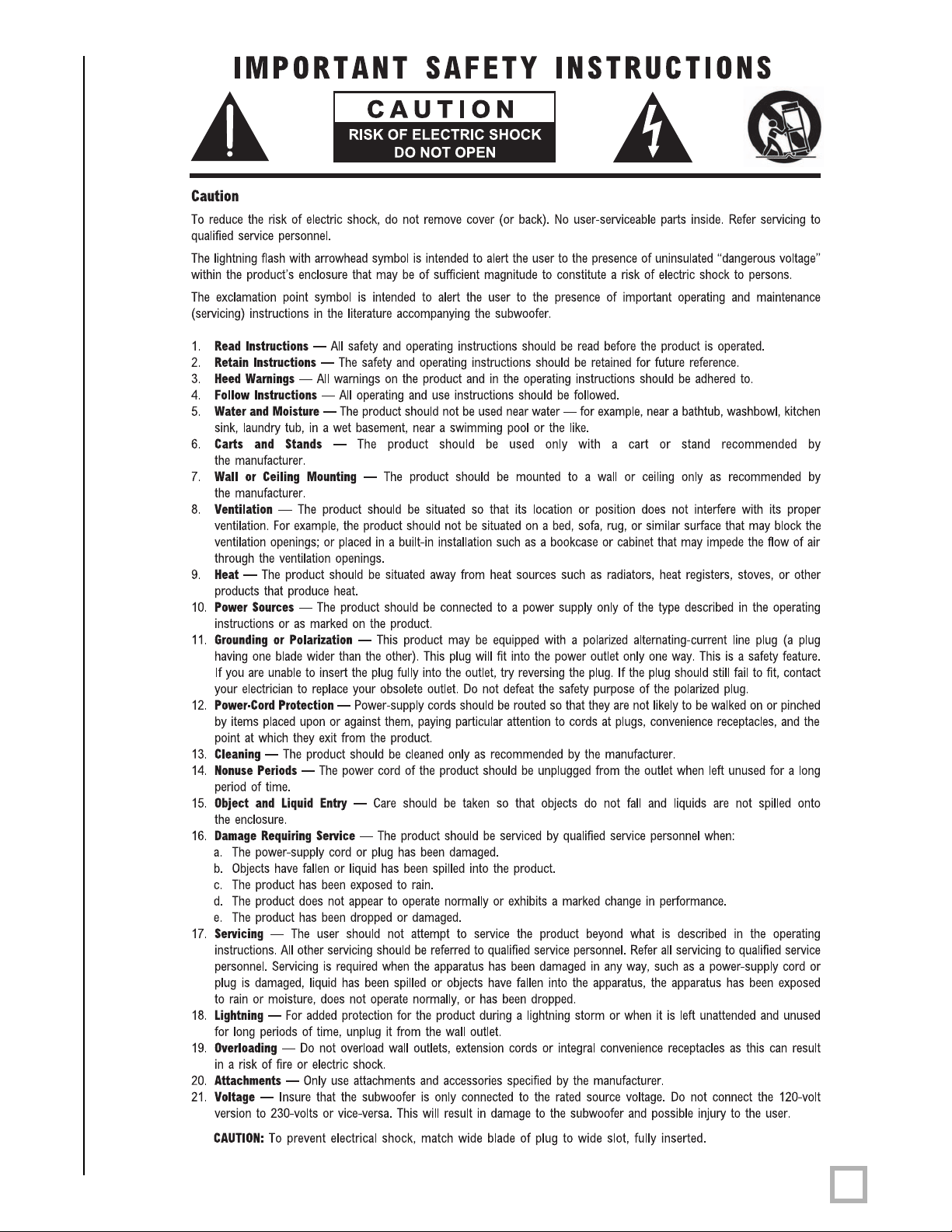
Caution!
Please observe the following instructions to insure safe and proper system operation.
Note: Do not leave unit in direct sunlight or use in high humidity environments!!!
Warning!
To prevent fire or shock hazard, do not expose this equipment to rain or moisture. To avoid
electrical shock, do not open speaker enclosure or amp chassis cover. Please observe all
warnings on the equipment itself. There are no user serviceable parts inside. Please refer all
service questions to your authorized Velodyne dealer.
Prior to Installation:
Please unpack the system car
avoid injur
unit in any other carton may result in severe damage when shipping. Record the serial number
in the space provided on page 12 for futur
y. Please save the carton and all packaging materials for future use. Packing this
efully. This unit is heavy. Use caution when lifting or moving to
e reference.
Product Features
• A single driver consisting of:
- 8” (6.5” piston diameter) driver with 2.5” high-temp voice coil and
204 ounce magnet structure
• Built-in 2000 watts Dynamic/1000 watts RMS high efficiency Class D amplifier
• Adjustable (40 to 120 Hz) low-pass crossover (defeatable)
• Line-level (RCA) inputs and outputs
• LFE Input
• Speaker
• Signal sensing auto tur
• Variable volume control
• Selectable phase control (0° or 180°)
• Multiple staggered low-pass crossovers; 12 dB/octave initial, 48 dB/octave ultimate
• Driver Displacement Control circuit prevents over excursion and amp clipping
• Blue power indicator LED
• High-excursion EPDM rubber surround
• Oversized spider for linearity at high excursion
-level inputs with five way binding post connections
n on/off (defeatable)
.
www.velodyne.com
VMS User’s Manual
1

Prepare for Installation
Y
our new Velodyne subwoofer provides for a number of installation options. Read all the
installation information below in order to determine which installation option is best for your
system.
prevent possible damage.
Placement
The first step in installing your new VMS is to determine where it will be placed in the room.
Unpack the system carefully and use the following guidelines in order to find the best
room placement option.
True subwoofers operate at extremely low frequencies which are primarily omni-directional.
Keep in mind that frequency response and output level can be drastically influenced by
placement, depending on the acoustic properties of the listening room. To obtain optimum
output from your subwoofer, place it within a foot of a corner. This location will offer the greatest
output levels and optimum low frequency extension. If at all possible, your subwoofer should be
placed along a wall. The worst location for a subwoofer is typically far away from any walls and
close to the center of your room. Avoid these locations when possible. When using a pair of
Velodyne subwoofers in stereo, it is preferable to place each subwoofer near the satellite of the
same channel.
Remember to perform all installation procedures with system power turned off to
Depending on the size and type of furnishings in the room, perfect placement may not be
possible. Finding the best location within your environment will likely require some
experimentation. W
best to you when seated in your typical listening position.
Regardless of where you install your V
(woofer facing forward). Using, shipping or storing the subwoofer in any other position for an
extended period of time may r
Caution!
This subwoofer has electronics built into the cabinet. Do not place the cabinet next to
sources of heat such as furnace registers, radiators, etc. Do not place the unit near sources
of excessive moistur
be routed in such a way that it will not be walked on, pinched or compressed in any way that
could result in damaging the insulation or wire.
e suggest you experiment with the location during setup to find what sounds
elodyne subwoofer, it must remain in an upright position
esult in damage to the unit not covered by warranty.
e, such as evaporative coolers, humidifiers, etc. The power cor
d should
.
www.velodyne.com
VMS User’s Manual
2
 Loading...