

Page 1
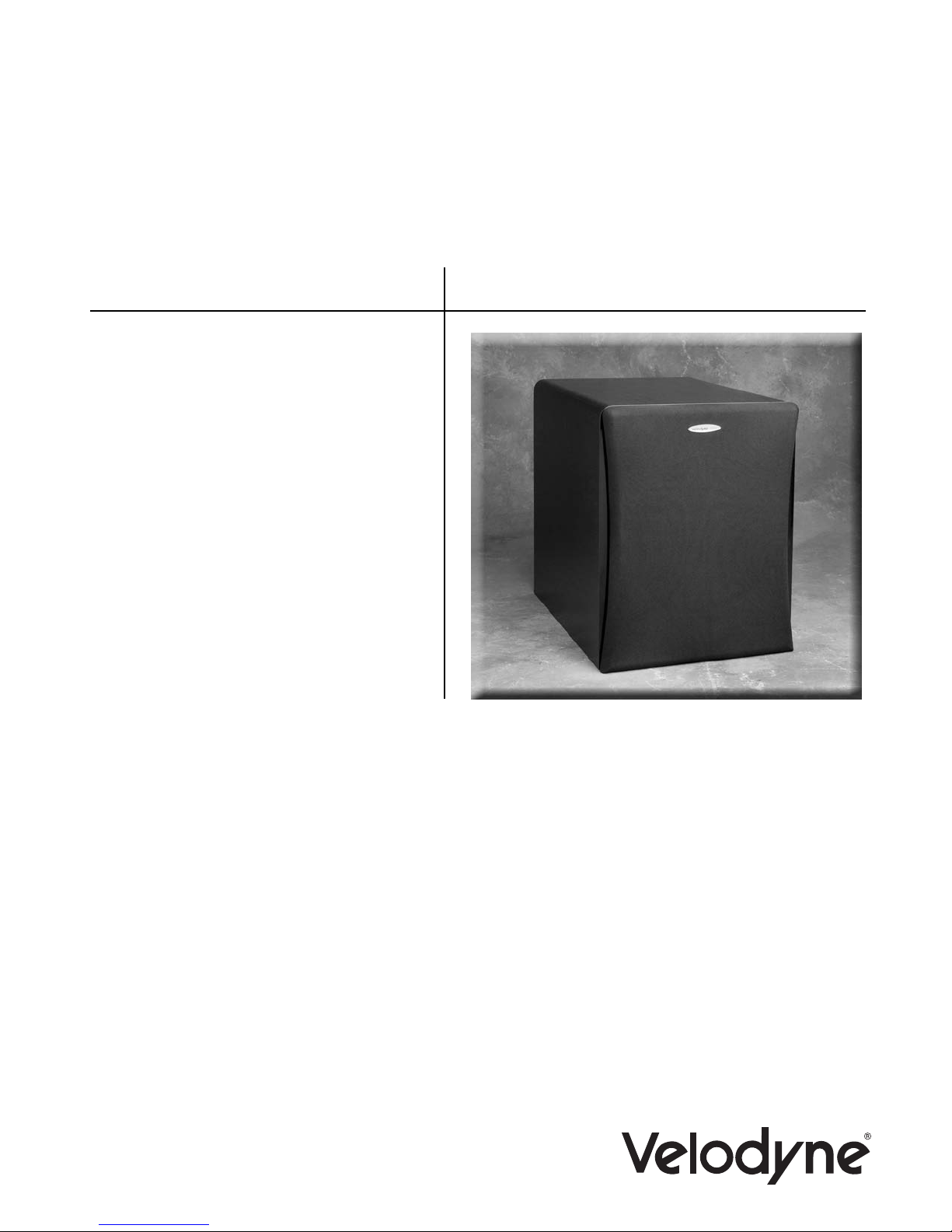
VRP Series
VRP-1000
VRP-1200
USER’S
MANUAL
Home Theater Subwoofer
Page 2
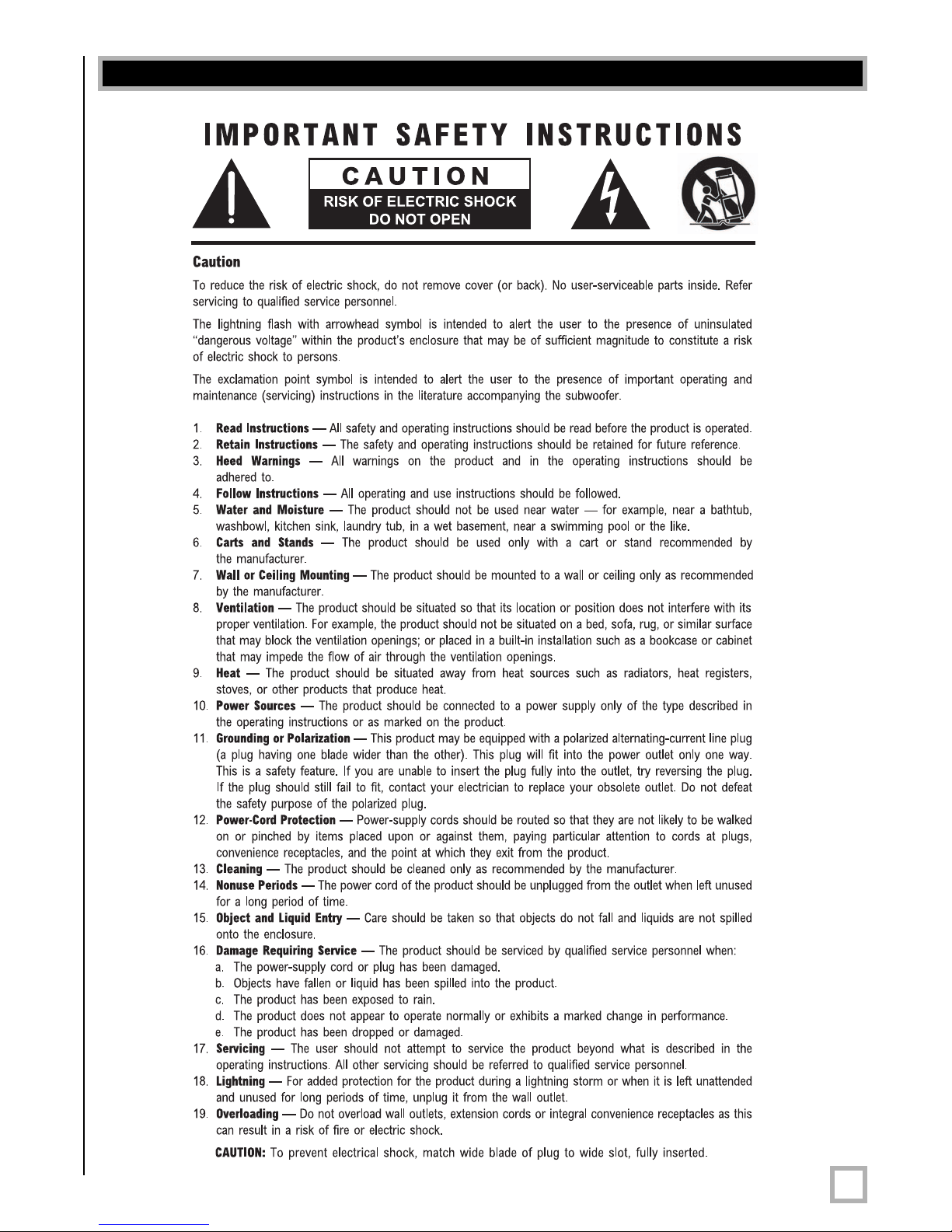
Caution
.
www.velodyne.com
VRP User’s Manual
i
Page 3

Table of Contents
C
ongratulations . . . . . . . . . . . . . . . . . . . . . . . . . . . . . . . . . . . . . . . . . . . . . . . . . . . .1
Installation . . . . . . . . . . . . . . . . . . . . . . . . . . . . . . . . . . . . . . . . . . . . . . . . . . . . . . .2
Rear Panel Connections . . . . . . . . . . . . . . . . . . . . . . . . . . . . . . . . . . . . . . . . . . . . . .5
Crossovers . . . . . . . . . . . . . . . . . . . . . . . . . . . . . . . . . . . . . . . . . . . . . . . . . . . . . . .6
Interconnect Cables . . . . . . . . . . . . . . . . . . . . . . . . . . . . . . . . . . . . . . . . . . . . . . . . .9
Care of Your Subwoofer . . . . . . . . . . . . . . . . . . . . . . . . . . . . . . . . . . . . . . . . . . . . . .9
Protection Circuitry . . . . . . . . . . . . . . . . . . . . . . . . . . . . . . . . . . . . . . . . . . . . . . . . .9
Troubleshooting and Service . . . . . . . . . . . . . . . . . . . . . . . . . . . . . . . . . . . . . . . . . .10
Specifications . . . . . . . . . . . . . . . . . . . . . . . . . . . . . . . . . . . . . . . . . . . . . . . . . . . .11
Other Velodyne Products . . . . . . . . . . . . . . . . . . . . . . . . . . . . . . . . . . . . . . . . . . . . .12
.
www.velodyne.com
VRP User’s Manual
ii
Page 4

Congratulations
C
ongratulations on your purchase of a Velodyne Rear Port (VRP™) subwoofer system. This
system represents the state-of-the-art in home audio reproduction and will provide you with
years of listening pleasure when properly cared for. Read and follow this instruction manual to
insure safe and proper system connection and operation.
Caution!
Please observe the following instructions to insure safe and proper system operation.
Note: Do not leave unit in direct sunlight or use in high humidity environments!!!
Warning!
To prevent fire or shock hazard, do not expose this equipment to rain or moisture. To avoid
electrical shock, do not open speaker enclosure or amp chassis cover. Please observe all
warnings on the equipment itself. There are no user serviceable parts inside. Please refer all
service questions to your authorized Velodyne dealer.
Prior to Installation:
Please unpack the system carefully. This unit is heavy. Use caution when lifting or moving to
avoid injury. Remove all staples used to seal the carton as they can scratch the cabinet. Please
save the carton and all packaging materials for future use. Packing this unit in any other carton
may result in severe damage when shipping. Record the serial number in the space provided
on page 13 for futur
e reference.
Product Features
• A single driver consisting of either:
- 10” (8.2” piston diameter) subwoofer with 2.0” high-temp voice coil
and 40 ounce motor structure or,
- 12” (9.7” piston diameter) subwoofer with 2.0” high-temp voice coil
and 40 ounce motor structure
• Adjustable (50 to 200 Hz) low-pass crossover with a 12 dB/octave slope
• Line-level (RCA) inputs
• Speaker-level inputs and outputs with spring loaded terminals
• Signal sensing auto turn on/off
• Variable volume control
• Selectable phase control (0° or 180°)
een power on/ Red power standby mode indicator LED
• Gr
Prepare for Installation
Your new Velodyne subwoofer provides for a number of installation options. Read all the
installation information below in order to determine which installation option is best for your
system.
to prevent possible damage.
Remember to perform all installation procedures with system power turned off
.
www.velodyne.com
VRP User’s Manual
1
Page 5
Placement
True subwoofers operate at extremely low frequencies that are primarily omni-directional. Keep
i
n mind that frequency response and output level can be
depending on the acoustic properties of the listening room. Typically, the optimum location for
a subwoofer is tucked away in a corner of your listening room. This location will usually offer the
greatest output levels and optimum low frequency extension. The worst location for a subwoofer
is typically far away from any walls, and close to the center of your room. Avoid these locations
when possible. When using a pair of Velodyne subwoofers in stereo, it is preferable to place
each subwoofer by the satellite of the same channel.
Caution! This subwoofer has electronics built into the cabinet. Do not place the cabinet
next to sources of heat such as furnace registers, radiators, etc., or near sources of
excessive moisture, such as evaporative coolers, humidifiers, etc. The power cord
should be routed in such a way that it will not be walked on, pinched, or compressed in
any way that could result in damaging the insulation or wire.
Regardless of where you install your Velodyne subwoofer, it must remain in an upright position
(woofer facing forward). Using, shipping, or otherwise storing the subwoofer in any other
position for an extended period of time may result in damage to the unit not covered
by warranty.
Your VRP subwoofer is magnetically shielded to reduce the amount of stray magnetic energy
emitted from the speaker’s motor structure. This greatly increases flexibility when placing the
unit close to video monitors, as there is ver
are par
after installing your subwoofer, simply increase the distance between your television and the
subwoofer until normal color and operation is returned.
ticularly sensitive to stray magnetic fields. If your television produces distorted colors
y little stray magnetism. Cer
d
rasticallyinfluenced by placement,
tain types of televisions
Your new Velodyne subwoofer, like any good speaker system, requires proper positioning within
the listening space to provide maximum performance. Improperly placed speakers may degrade
the sound quality and reduce your listening pleasure. Depending on the size and type of
furnishings in the room, perfect placement may not be possible. Finding the best location for
your environment will likely require some experimentation. We suggest you experiment with
the location during setup to find what sounds best to you when seated in your typical
listening position.
Installation
Inputs
Your new subwoofer is equipped with speaker-level and line-level inputs. Use the LINE LEVEL
jacks when connecting your subwoofer to a pre-amp, signal processor (such as LFE out), line-
eceiver with pr
level cr
receivers may not provide enough signal to have the unit’s auto-on feature operate properly.
Additionally, this lack of signal may also cause the subwoofer to produce less output than it is
capable of.
ossover
, or r
e-amp level outputs. When using the line level jacks, some
.
www.velodyne.com
VRP User’s Manual
2
Page 6

T
o alleviate this condition, we recommend the following steps:
1
) If using line level jacks, BOTH THE LEFT AND RIGHT INPUT SHOULD ALWAYS BE USED
– never use just the left or just the right input. If the subwoofer’s input comes from the
LFE channel of your receiver, use the included “Y” splitter to divide the single input into
two inputs for the Left and Right subwoofer inputs. If using line level connections from
a preamp or signal processor, use both Left and Right inputs from your preprocessor or
preamp and connect them to the Left and Right inputs on your subwoofer.
2) If using a receiver with LFE out, be sure the LFE channel is sending adequate signal to
the subwoofer. We recommend setting the subwoofer’s level to the 9 o’clock position
(the 1/4 volume setting) and then adjust the LFE channel on your receiver or processor
to achieve the desired bass output. See your receiver or processor’s owner’s manual for
more information.
The
SPEAKER LEVEL jacks connect directly to the speaker outputs of any amplifier, integrated
amplifier, or receiver. Your amplifier section will notice no additional loading effects when you
use these inputs due to their very high impedance. If using the
DO want to connect both channels, since different bass information might be present in each
channel going to your main speakers.
SPEAKER LEVEL inputs, you
IMPOR
Do not use both LINE LEVEL and SPEAKER LEVEL connections simultaneously!
Caution!!! To avoid damage to your main amplifier, be sur
when making all connections - red (positive) to red, and black (negative) to black. Be
sure all connections are tight, and that there are no loose strands or frayed wires.
TANT!!!
e to maintain correct polarity
Volume Control
This contr
speakers/amplifier in your system. This contr
from both the main speakers and subwoofer when listening to music. A good starting point for
the volume control is two or three graduations from minimum.
ol allows you to balance the output from the subwoofer to the main
ol should be set to achieve similar output levels
Low-pass Crossover - 50 to 200 Hz
As noted above, all inputs sum the left and right channels together, with the resulting signal
passing thr
allows you to adjust the upper limit of the subwoofer’s frequency response from 50 to 200 Hz.
The subwoofer’s response will begin rolling off above the frequency you set this control to. You
should set the cr
subwoofer to the main speakers in your system. If your main speakers are smaller units with
limited low frequency output, you may wish to choose a higher frequency (such as 100 - 120
Hz) than you would with larger speakers which have greater low frequency output. With larger
speakers, you might star
ough an adjustable low-pass cr
ossover frequency to obtain a smooth and seamless transition from the
t with this contr
ossover befor
ol set lower
e being amplified. The cr
, such as 80 Hz.
ossover contr
ol
.
www.velodyne.com
VRP User’s Manual
3
Page 7

Phase Adjustment - 0°/180°
This control allows you to “reverse” the phase of the subwoofer’s output signal 180° to correct
f
or any possible mismatch and resulting cancellation between the subwoofer and your main
speakers/amplifier. To adjust, simply listen to the system with music playing, then depress the
phase switch from one position to the other and listen for a change in low frequency output.
The correct position will have a greater amount of apparent low frequency output.
For all installations, experiment with the phase switch to determine the setting (0 or 180
degrees) that produces the most bass. If the settings sound similar, we recommend the
“0” position.
Auto Turn on Function
The subwoofer will turn itself on automatically when an audio signal is present. If no signal is
present for approximately eight minutes, the unit will switch to standby mode (Red LED). While
in standby mode, your subwoofer will draw very minimal power.
.
www.velodyne.com
VRP User’s Manual
4
Page 8
Rear Panel Connections
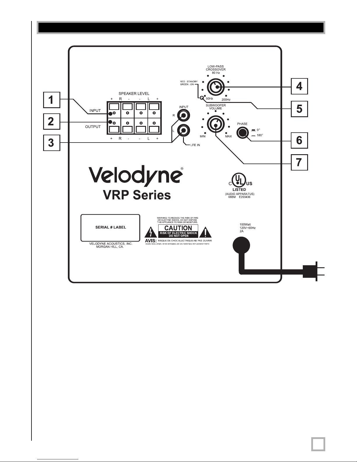
Figure 1.VRP Rear Panel Connections
Figure 1 shows the connections on the rear panel of the VRP. Following are brief descriptions
of the connections described in Figure 1. More detail of these connections can be found below:
(1)
(2)
(3) LINE INPUT jacks - Connect these jacks to the LINE OUT jacks of the amplifier.
(4) LOW-PASS CROSSOVER - Use this knob to select the high-frequency range at which
.
www.velodyne.com
SPEAKER LEVEL INPUT ter
output terminals of your amplifier or receiver.
SPEAKER LEVEL OUTPUT ter
is output from these terminals.
you wish to cut-of
minals - Connect these input ter
minals - The speaker
f the signal to the subwoofer
minals to the speaker
-level signal to the front speakers
.
VRP User’s Manual
5
Page 9

(
5) Power indicator - Red: Unit is in standby mode. Green: Unit is in operation mode.
(automatically turns to STANDBY mode if no signal for eight minutes)
(
6) PHASE switch - Select the switch position at which you hear a louder bass sound.
(7) VOLUME LEVEL knob - Use this knob to adjust the output level of the subwoofer.
Crossovers
Receiver/Processor Subwoofer Outputs
The Velodyne subwoofer is designed to operate using the full range audio signal for input when
using the built-in crossover. Many home theater processors/receivers (Dolby Digital™, DTS™,
THX™) have a “subwoofer out” jack (sometimes labeled “LFE”) that is internally filtered, settable
at the receiver/processor, and designed to be used with a powered subwoofer. In some
installations, it may be beneficial to use BOTH the Velodyne crossover and the
receiver/processor crossover, resulting in a steeper ultimate crossover slope. In some rare
cases, combining both an external crossover and the one internal to the subwoofer may result
in low output and increased noise. In these installations you may need to bypass the crossover
in either the pr
frequency (such as 120 Hz) will restore maximum performance.
ocessor or your VRP subwoofer, or simply setting one crossover to a higher
(Refer to Figur
Subwoofer Connection Diagram, pages 7 and 8 for connection diagrams.)
e 2a Line-Level Subwoofer Connection Diagram and Figure 2b Speaker-Level
.
www.velodyne.com
VRP User’s Manual
6
Page 10
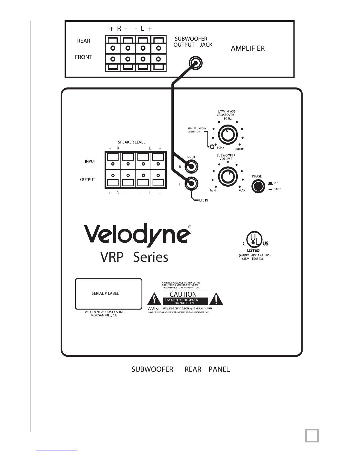
Figure 2a. Line-Level Subwoofer Connection Diagram
.
www.velodyne.com
VRP User’s Manual
7
Page 11
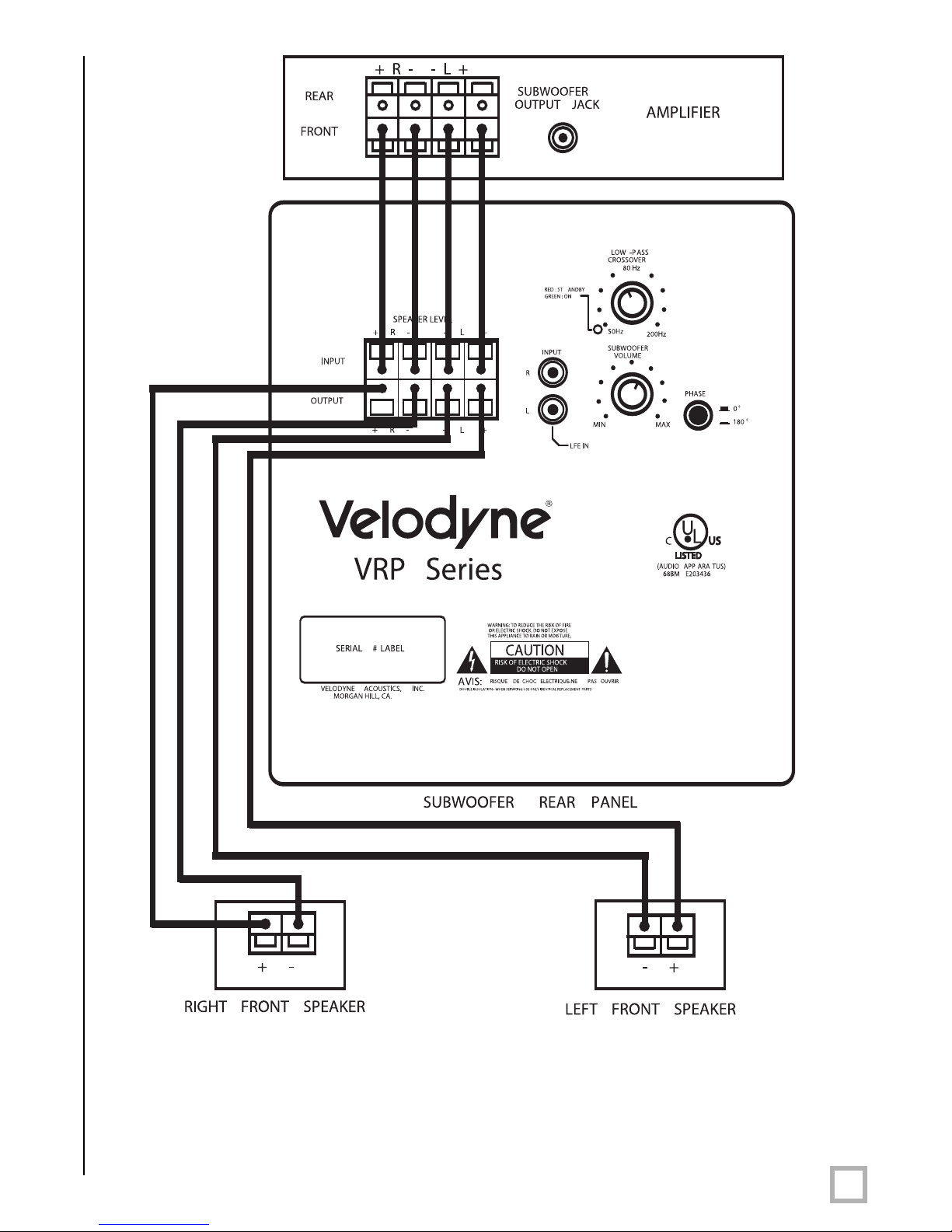
RIGHT FRONT SPEAKER, LEFT FRONT SPEAKER
Figure 2b. Speaker-Level Subwoofer Connection Diagram
.
www.velodyne.com
VRP User’s Manual
8
Page 12

Interconnect Cables
W
hen installing your new Velodyne subwoofer using the line level connections, you should
always use shielded phono cables. There are many high quality cables available today. It is
recommended that you keep the length of cable as short as possible to avoid any potential
noise problems.
When using speaker level connections, use a high quality speaker cable that mates well with
the connectors. Be very careful to avoid any loose strands or frayed wires that may result in a
short, which may damage your equipment. Cables of extremely large size are typically not
required. Extremely large gauge wire may not properly fit in the binding posts, resulting in a
poor connection and possible short circuits.
Care of Your Subwoofer
Your Velodyne subwoofer does not require any regular maintenance. Normal dusting or cleaning
of the surface for appearance purposes is all that is required. We suggest you avoid any harsh
detergents or chemicals when cleaning the cabinet. Abrasives, detergents, or cleaning
solutions may damage the finish on the cabinet. We recommend using only a damp cloth to
clean the cabinet.
During normal conditions, your new subwoofer may be left on continuously without any
problems. The unit is equipped with a signal-sensing tur
the unit when a signal is present at the inputs and turn off the unit after several minutes when
there is no longer any signal at the inputs.
n on/off that will automatically turn on
Protection Circuitry
Your new subwoofer is equipped with circuitry to provide maximum performance with
greatest reliability.
The unit is pr
1) Overheating the amplifier.
2) Excessive drop in power line voltage.
If either of the above should happen, you should reduce the volume setting or shut the unit off
until normal operating conditions return. You may also want to plug the unit into a different wall
outlet, as dr
may result in the unit shutting down intermittently.
otected against:
opping power line voltage will be most noticeable under str
enuous conditions and
.
www.velodyne.com
VRP User’s Manual
9
Page 13

Troubleshooting and Service
I
f you should experience a problem with the operation of your subwoofer, please check all of the
following before seeking service. Following is a simple troubleshooting guide to assist you.
1. Verify that the unit is plugged in, the power outlet is active, and is supplying
proper voltage.
2. Is unit receiving an input signal from your source?
3. Have all controls on subwoofer (volume, crossover, phase, etc.) been properly set?
4. If unit has been running at high levels for an extended period of time, one of the
protection circuits may be engaged.
• Is the built-in amplifier extremely hot to the touch?
• Is your power line voltage sagging, such as when there are other devices on the
same circuit drawing lots of power?
If the protection circuitry is active, the unit may cycle on and off until operating parameters
return to normal. Under more serious conditions, the unit may shut off completely. Normal
operation should return upon cooling, but you may be required to turn the power off and then
on again to reset the unit.
The following conditions r
1. The power cord has become damaged.
2. The unit does not appear to operate nor
change in performance.
3. The unit has been exposed to water.
4. Some part of the cabinet or circuitry is physically damaged.
equire service by a qualified technician:
mally or exhibits a marked
Thank You for Purchasing a Velodyne!
.
www.velodyne.com
VRP User’s Manual
10
Page 14
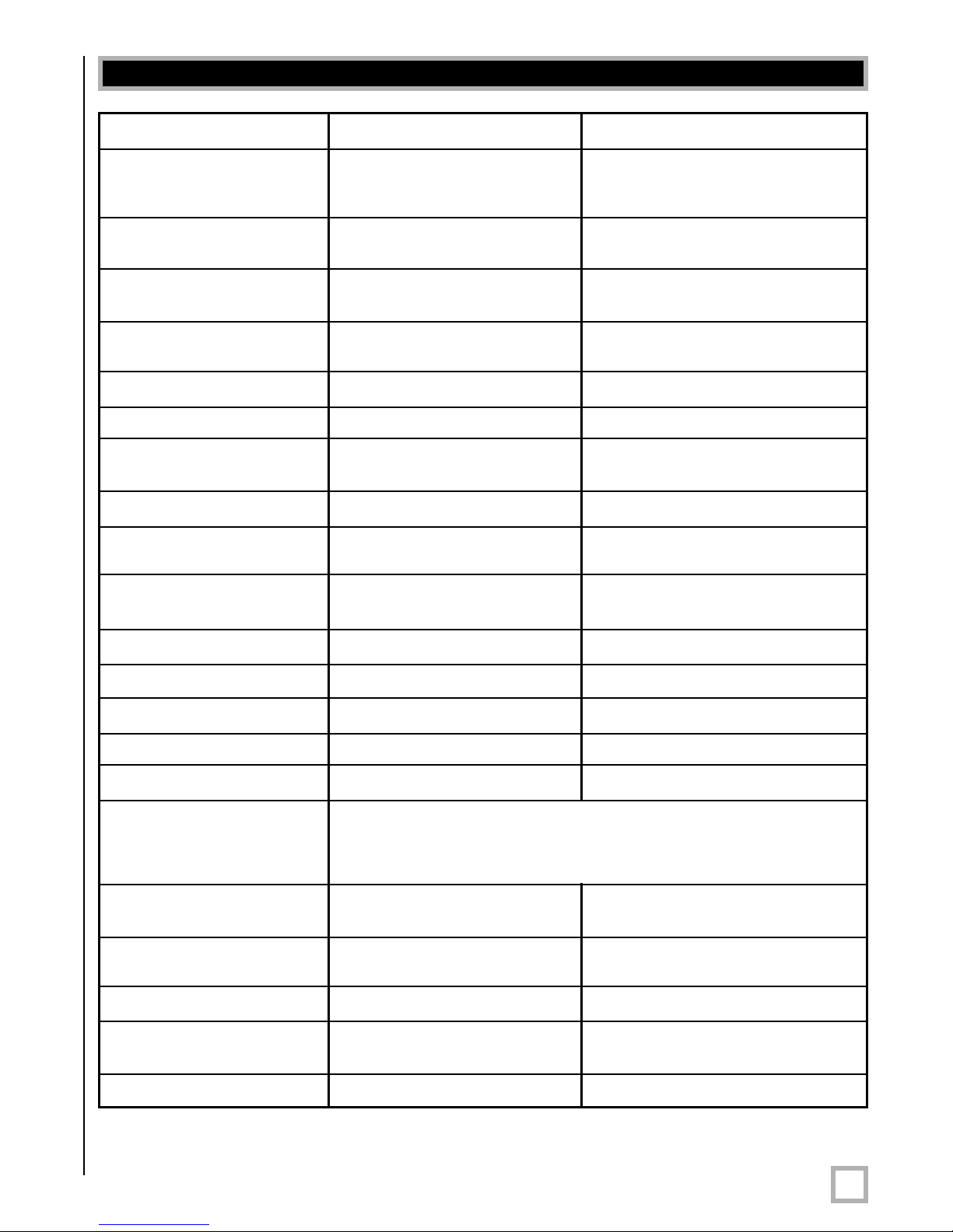
Specifications
SPECIFICATIONS VRP-1000 VRP-1200
oofer 10” (24.5 cm) 12” (30.5 cm)
W
orward firing foward firing
f
(8.2” piston diameter) (9.7” piston diameter)
Amplifier: Monolithic MOS 170 watts Dynamic/ 195 watts Dynamic/
lass A/B 115 watts RMS Power 130 watts RMS Power
C
Cabinet Design Acoustically neutral, Acoustically neutral,
rear ported rear ported
Frequency Response 35 -140 Hz 29 - 140 Hz
(+/-3 dB) (+/-3 dB)
Voice Coil 2” copper-wound 2” copper-wound
Cone Coated Fiber Coated Fiber
Speaker-Level Full Range Full Range
Pass-Through
Low-Pass Crossover 50 - 200 Hz 50 - 200 Hz
Outputs
Inputs RCA Line Level, LFE and RCA Line Level, LFE and
Phase 0° or 180° 0° or 180°
Auto On/Off Yes Yes
Removable Grill Yes Yes
Video Shielding Yes Yes
LED Power Indicator Yes Yes
Input Impedance 65K ohm
Sensitivity Speaker-Level 1.0V 1.0V
Line
Power Supply 120V, 60 Hz AC 120V, 60 Hz AC
Left and right speaker Left and right speaker
level pass-through level pass-through
Speaker Level inputs Speaker Level inputs
(for LINE INPUT jacks)
1.2K ohm
(for SPEAKER LEVEL INPUT terminals)
100 mV 100 mV
Power Consumption
Cabinet (H,W
(cm) with grill 38 x 31 x 41 42 x 37 x 48
Weight (approx.) 37 lbs. (17 Kg) 44 lbs. (20 Kg)
.
www.velodyne.com
,D) 15” x 12.1” x 16.1” 16.5” x 14.5” x 18.75”
Specifications ar
75 watts 75 watts
e subject to change without notice.
VRP User’s Manual
11
Page 15
Other Velodyne Products:
110V
DD™ Series
DD-10
DD-12
DD-15
DD-18
Digital Drive 1812
Signature Edition
DLS™-R Series
DLS-3500R
-3750R
DLS
DLS-4000R
DLS-5000R
DPS™ Series
DPS-10
DPS-12
MiniVee™
SMS™-1
SPL™-R Series
SPL-800R
SPL-1000R
SPL-1200R
-1500R
SPL
SubContrator™
Series
SC-1250
SC-8
SC-10
SC-12
SC-15
SC-IW
SC-IF
SC-IC
230V
DD™ Series
DD-10
DD-12
DD-15
DD-18
Digital Drive 1812
Signature Edition
CHT-R Series
CHT-8R
CHT-10R
CHT-12R
CHT-15R
SMS™ -1
SPL-800i
SPL™-R Series
SPL-800R
SPL-1000R
SPL-1200R
-1500R
SPL
SubContrator™
Series
SC-1250
SC-8
SC-10
SC-12
SC-15
SC-IW
SC-IF
SC-IC
.
www.velodyne.com
VX™ Series
VX-10
VRP User’s Manual
12
Page 16
FOR YOUR RECORDS. . .
Date Puchased_________________________________________________________________
Dealer_________________________________________________________________________
Serial #________________________________________________________________________
*NOTE: Please complete and return your warranty card within ten (10) days or
Register. . . ON LINE . . . It’s faster . . . and easier
www.velodyne.com
LIMITED WARRANTY
VELODYNE ACOUSTICS, Inc. (“VELODYNE”) warrants all electronics and powered subwoofers for a period of two
years and full range speakers for a period of five years. All VELODYNE products have a warranty from the date of
purchase against defects in materials and workmanship subject to the following conditions:
1. VELODYNE is not responsible for defects which result from the use of an amplifier or controller other than
the one originally supplied with the unit (subwoofer) or defects which result from modifications or repairs
made by any component of the system by anyone other than a VELODYNE factory authorized
service representative.
2. This warranty is void if any repairs or service covered by the terms of this warranty are made to any
component of the system by anyone other than a VELODYNE factory authorized service representative.
3. VELODYNE is not responsible for damage caused by accidents, abuse, misuse, natural or personal disaster
or unauthorized modification. The VELODYNE products are not intended for professional or commercial use
and VELODYNE is not responsible for damage resulting from such use.
4. The VELODYNE product warranty is limited to units that are purchased from authorized VELODYNE dealers
and finalized within authorized dealer locations.
5. This warranty is nontransferable under any condition.
TO OBT
Information r
VELODYNE customer ser
representative within the warranty period set forth above. If VELODYNE determines the unit is defective, VELODYNE
will, at VELODYNE’
authorized service representative. Products forwarded to the factory authorized service representative should be
shipped securely and properly packaged, insured and freight prepaid.
egarding service may be obtained from the dealer from whom you purchased the unit, or by contacting
vice. Warranty service must be performed by a VELODYNE factory authorized service
s option, r
epair or r
eplace the pr
AIN SERVICE
oduct at no char
ge if the product is forwarded prepaid to a factory
.
www.velodyne.com
VRP User’s Manual
13
Page 17

Technical E
63-VRP1012 Rev B JUL06
.
www.velodyne.com
Velodyne Acoustics, Inc.
345 Digital Drive
Morgan Hill, CA 95037
408.465.2800 voice
408.779.9227 fax
408.779.9208 ser
www
.velodyne.com
Service E
Product E
-mail: [email protected]
-mail: [email protected]
-mail: [email protected]
vice fax
VRP User’s Manual
14
 Loading...