

Velodyne VLP-16 User Manual

VLP-16 User Manual
63-9243 Rev. D

Copyright 2018 Velodyne LiDAR, Inc. All rights reserved.
Trademarks
Velodyne™, HDL-32E™, HDL-64E™, VLP-16™, VLP-32™, Puck™, Puck LITE™, Puck Hi-Res™, and Ultra Puck™ are trademarks of Velodyne LiDAR, Inc. All other trademarks, service marks, and company names in this document or website are
properties of their respective owners.
Disclaimer of Liability
The information contained in this document is subject to change without notice. Velodyne LiDAR, Inc. shall not be liable for
errors contained herein or for incidental or consequential damage in connection with the furnishing, performance, or use
of this document or equipment supplied with it.
The materials and information contained herein are being provided by Velodyne LiDAR, Inc. to its Customer solely for Customer’s use for its internal business purposes. Velodyne LiDAR, Inc. retains all right, title, interest in and copyrights to the
materials and information herein. The materials and information contained herein constitute confidential information of
Velodyne LiDAR, Inc. and Customer shall not disclose or transfer any of these materials or information to any third party.
No part of this publication may be reproduced or transmitted in any form or by any means, electronic or mechanical, including photocopying and recording, or stored in a database or retrieval system for any purpose without the express written
permission of Velodyne LiDAR, Inc., which reserves the right to make changes to this document at any time without notice
and assumes no responsibility for its use. This document contains the most current information available at the time of publication. When new or revised information becomes available, this entire document will be updated and distributed to all
registered users.
Limited Warranty
Except as specified below, products sold hereunder shall be free from defects in materials and workmanship and shall conform to Velodyne's published specifications or other specifications accepted in writing by Velodyne for a period of one (1)
year from the date of shipment of the products. The foregoing warranty does not apply to any Garmin products, other
products not manufactured by Velodyne or products that have been subject to misuse, neglect, or accident, or have been
opened, dissembled, or altered in any way. Velodyne shall make the final determination as to whether its products are
defective. Velodyne 's sole obligation for products failing to comply with this warranty shall be, at its option, to either repair,
replace or issue credit for the nonconforming product where, within fourteen (14) days of the expiration of the warranty
period, (i) Velodyne has received written notice of any nonconformity; (ii) after Velodyne's written authorization, Buyer has
returned the nonconforming product to Velodyne at Buyer's expense; and (iii) Velodyne has determined that the product is
nonconforming and that such nonconformity is not the result of improper installation, repair or other misuse. Velodyne will
pay for return shipping for all equipment repaired or replaced under warranty and Buyer will pay all duties or taxes, if any,
on all equipment repaired or replaced under warranty. THE FOREGOING WARRANTY AND REMEDIES ARE
EXCLUSIVE AND MADE EXPRESSLY IN LIEU OF ALL OTHER WARRANTIES, EXPRESSED, IMPLIED OR
OTHERWISE, INCLUDING WARRANTIES OF 65-0003 Rev E Velodyne LiDAR Terms & Conditions Page 3 of 5 201603-31 MERCHANTABILITY AND FITNESS FOR A PARTICULAR PURPOSE. VELODYNE DOES NOT ASSUME OR
AUTHORIZE ANY OTHER PERSON TO ASSUME FOR IT ANY OTHER LIABILITY IN CONNECTION WITH ITS
PRODUCTS. This warranty is non-transferable.
Velodyne LiDAR, Inc.
5521 Hellyer Ave
San Jose, CA 95138
Phone +1 408-465-2800
Revision History
Sensor Firmware
VLP-16 3.0.37.0 2017-12-12
Release
Date
Release Notes
• CHANGED: Phase Lock Offset setting now expects
integer degrees instead of hundredths of degrees.
• IMPROVED: Removed 'Update Calibration' from System
tab.
• IMPROVED: Sun Noise Filter.
• ADDED: Ability to change sensor's Ethernet MAC
Address from Web Interface.
• IMPROVED: Low signal cross-talk filtering performance.
• IMPROVED: Firmware update messages during update.
• IMPROVED: Phase Lock rotations error < ±5 degrees.
• FIXED: Intermittent ghost returns at 40, 80 and greater
than 124 meters.
• IMPROVED: Several JSON data additions and changes.
• ADDED: Reverse rotation capability. Specify negative
RPM values to use this capability.
For details, see the full Release Notes at http://www.ve-
lody nelidar.com/downloads.html#firmware.
3

Table of Contents
Chapter 1 • About This Manual
1.1 Manual Scope
1.2 Prerequisite Knowledge
1.3 Audience
1.4 Document Conventions
Chapter 2 • VLP-16 Overview
2.1 Overview
2.2 Product Models
2.3 Time of Flight
2.4 Data Interpretation Requirements
Chapter 3 • Safety Precautions
3.1 Warning and Caution Definitions
3.1.1 Caution Hazard Alerts
3.2 Safety Overview
3.2.1 Electrical Safety
3.2.2 Mechanical Safety
3.2.3 Laser Safety
Chapter 4 • Unboxing & Verification
16
16
16
16
18
19
19
19
20
20
20
20
20
21
4.1 What’s in the Box?
4.1.1 Variants
4.2 Verification Procedure
4.2.1 Network Setup in Isolation
4.2.2 Access Sensor’s Web Interface
4.2.3 Visualize Live Sensor Data with VeloView
4.2.3.1 VeloView Operation
22
22
22
23
24
26
27
Chapter 5 • Installation & Integration
5.1 Overview
5.2 Mounting
5.3 Encapsulation, Solar Hats, and Ventilation
4 VLP-16 User Manual
29
29
30

5.4 Connections
30
5.4.1 Integrated Cable and Interface Box
5.4.2 Operation Without an Interface Box
5.4.3 Power
Chapter 6 • Key Features
6.1 Calibrated Reflectivity
6.2 Laser Return Modes
6.2.1 Single Return Modes: Strongest, Last
6.2.2 Multiple Returns
6.2.3 Dual Return Mode
6.3 Phase Locking Multiple Sensors
Chapter 7 • Sensor Inputs
7.1 Power Requirements
7.2 Interface Box Signals
7.3 Ethernet Interface
7.4 GPS, Pulse Per Second (PPS) and NMEA GPRMC Message
7.4.1 GPS Input Signals
7.4.2 Electrical Requirements
31
31
31
32
32
32
33
33
37
39
40
41
41
41
41
7.4.3 Timing and Polarity Requirements
7.4.4 GPS Connection Scenarios
7.4.4.1 Connecting a Garmin 18x LVC GPS Receiver
7.4.4.2 Connecting to a computer's serial port
7.4.4.3 Connecting to a microcomputer’s UART
7.4.5 NMEA Message Formats
7.4.5.1 Pre-NMEA Version 2.3 Message Format
7.4.5.2 NMEA Version 2.3 Message Format
7.4.6 Accepting NMEA Messages Via Ethernet
Chapter 8 • Sensor Operation
8.1 Firing Sequence
8.2 Throughput Calculations
41
44
44
44
45
46
46
47
48
49
49
5

8.2.1 Data Packet Rate
49
8.2.2 Position Packet Rate
8.2.3 Total Packet Rate
8.2.4 Laser Measurements Per Second
8.2.4.1 Single Return Mode (Strongest, Last)
8.2.4.2 Dual Return Mode
8.3 Rotation Speed (RPM)
8.3.1 Horizontal Angular (Azimuth) Resolution
8.3.2 Rotation Speed Fluctuation and Point Density
Chapter 9 • Sensor Data
9.1 Sensor Origin and Frame of Reference
9.2 Calculating X,Y,Z Coordinates from Collected Spherical Data
9.3 Packet Types and Definitions
9.3.1 Definitions
9.3.1.1 Firing Sequence
9.3.1.2 Laser Channel
9.3.1.3 Data Point
9.3.1.4 Azimuth
50
50
50
50
50
50
50
51
52
52
54
54
55
55
55
55
9.3.1.5 Data Block
9.3.1.6 Time Stamp
9.3.1.7 Factory Bytes
9.3.2 Data Packet Structure
9.3.3 Position Packet Structure
9.4 Discreet Point Timing Calculation
9.5 Precision Azimuth Calculation
9.6 Converting PCAP Files to Point Cloud Formats
55
55
56
56
60
61
65
66
Chapter 10 • Sensor Communication
10.1 Web Interface
10.1.1 Configuration Screen
10.1.1.1 MAC Address
10.1.1.2 Correctly reset MAC Address to Factory MAC Address
6 VLP-16 User Manual
68
69
71
71

10.1.2 System Screen
72
10.1.3 Info Screen
10.1.4 Diagnostics Screen
10.2 Sensor Control with curl
10.2.1 Using curl with Velodyne LiDAR Sensors
10.2.2 curl Command Parameters
10.2.3 Command Line curl Examples
10.2.3.1 Get Diagnostic Data
10.2.3.2 Conversion Formulas
10.2.3.3 Interpret Diagnostic Data
10.2.3.3.1 top:hv
10.2.3.3.2 top:lm20_temp
10.2.3.3.3 top:pwr_5v
10.2.3.3.4 top:pwr_2_5v
10.2.3.3.5 top:pwr_3_3v
10.2.3.3.6 top:pwr_5v_raw
10.2.3.3.7 top:pwr_vccint
10.2.3.3.8 bot:i_out
73
75
76
76
76
77
77
78
78
78
79
79
79
79
79
80
80
10.2.3.3.9 bot:lm20_temp
10.2.3.3.10 bot:pwr_1_2v
10.2.3.3.11 bot:pwr_1_25v
10.2.3.3.12 bot:pwr_2_5v
10.2.3.3.13 bot:pwr_3_3v
10.2.3.3.14 bot:pwr_5v
10.2.3.3.15 bot:pwr_v_in
10.2.3.4 Get Snapshot
10.2.3.5 Get Sensor Status
10.2.3.6 Set Motor RPM
10.2.3.7 Set Field of View
10.2.3.8 Set Return Type (Strongest, Last, Dual)
10.2.3.9 Save Configuration
80
80
81
81
81
81
81
82
82
82
83
83
83
7

10.2.3.10 Reset System
83
10.2.3.11 Network Configuration
10.2.3.12 Set Host (Destination) IP Address
10.2.3.13 Set Data Port
10.2.3.14 Set Telemetry Port
10.2.3.15 Set Network (Sensor) IP Address
10.2.3.16 Set Netmask
10.2.3.17 Set Gateway
10.2.3.18 Set DHCP
10.2.4 curl Example using Python
Chapter 11 • Troubleshooting
11.1 Troubleshooting Process
11.1.1 Turned DHCP On, Lost Contact With Sensor
11.2 Service and Maintenance
11.2.1 Fuse Replacement
11.3 Technical Support
11.3.1 Purchased through a Distributor
11.3.2 Factory Support
83
83
84
84
84
84
84
84
84
87
88
89
89
90
90
90
11.3.3 Support Desk
11.4 Return Merchandise Authorization (RMA)
90
90
Appendix A • Sensor Specifications
Appendix B • Firmware Update
B.1 Firmware Update Procedure
B.1.1 Special Procedure to Update Firmware
B.1.2 If An Error Occurs
92
98
99
Appendix C • Mechanical Diagrams
C.1 Interface Box Mechanical Drawing
C.2 VLP-16 and Puck LITE Mechanical Drawing
C.3 VLP-16 and Puck LITE Optical Drawing
C.4 VLP-16 and Puck LITE Optical Keep Out Zone
8 VLP-16 User Manual
101
102
103
104

C.5 Puck Hi-Res Mechanical Drawing
105
C.6 Puck Hi-Res Optical Drawing
C.7 Puck Hi-Res Optical Keep Out Zone
Appendix D • Wiring Diagrams
D.1 Interface Box Wiring Diagram
D.2 Interface Box Schematic
Appendix E • VeloView
E.1 Features
E.2 Install VeloView
E.3 Visualize Streaming Sensor Data
E.4 Capture Streaming Sensor Data to PCAP File
E.5 Replay Captured Sensor Data from PCAP File
Appendix F • Laser Pulse
F.1 The Semiconductor Laser Diode
F.2 Laser Patterns
F.2.1 Laser Spot Pattern
F.2.2 Laser Scan Pattern
F.2.3 Beam Divergence
106
107
109
110
111
112
112
114
114
119
120
120
120
121
Appendix G • Time Synchronization
G.1 Introduction
G.2 Background
G.3 PPS Qualifier
G.3.1 Require GPS Receiver Valid
G.3.2 Require PPS Lock
G.3.3 Delay
G.4 GPS Qualifier
G.5 Application
G.6 Logic Tables
Appendix H • Phase Lock
H.1 Phase Lock
123
123
124
124
124
125
125
125
125
127
9

H.1.1 Setting the Phase Lock
127
H.1.2 Application Scenarios
H.2 Field of View
Appendix I • Sensor Care
I.1 Cleaning the Sensor
I.1.1 Required Materials
I.1.2 Determine Method of Cleaning
I.1.3 Method One
I.1.4 Method Two
I.1.5 Method Three
I.1.6 Method Four
Appendix J • Network Configuration
J.1 Ethernet and Network Setup
J.1.1 Defaults
J.1.2 Establishing Communication via Ethernet
J.2 Network Considerations
J.2.1 Throughput Requirements
J.2.2 Single Sensor Transmitting to a Broadcast Address
128
130
131
131
132
132
132
132
133
134
134
134
135
135
136
J.2.3 Multiple Sensors in the Same Network
J.2.3.1 Multiple Sensors Transmitting to a Broadcast Address
J.2.3.2 Multiple Sensors Transmitting to a Specific Address
136
136
137
10 VLP-16 User Manual

List of Tables
Table 1-1 Doc ument Conventions
Table 2-1 3D Sensing System Components
Table 7-1 Interface Box Signal s
Table 7-2 Pre-NMEA Versi on 2.3 Message Format
Table 7-3 Post-NMEA Version 2.3 Mes sage Format
Table 8-1 Rotation Speed vs Resoluti on
Table 9-1 Verti cal Angles (ω) by Las er ID and Model
Table 9-2 Factory Byte Values
Table 9-3 Position Packet Struc ture Field Offsets
Table 9-4 PPS Status Byte Values
Table 10-1 Configuration Screen Functionality and Features
Table 10-2 System Screen Functionality and Features
Table 10-3 Info Sc reen Functi onality and Features
Table 10-4 System Screen Functionality and Features
Table 11-1 Common Problems and Resolutions
Table F-1 VLP-16 Beam Div ergence
Table F-2 Dimensions of VLP-16 Laser Spots at Distance
16
19
40
47
47
51
53
56
60
60
69
72
73
75
87
122
122
11

List of Figures
Figure 2-1 Ex ample 3D Sensing Sy stem
Figure 3-1 Clas s 1 Las er
Figure 4-1 Sens or Network Settings
Figure 4-2 Interfac e Box (power and data connections )
Figure 4-3 Sample Web Interface Main Configuration Screen
Figure 4-4 VeloView Open Sens or Stream
Figure 4-5 VeloView Select Sensor Calibration
Figure 4-6 VeloView Sensor Stream Display
Figure 5-1 Mounting Details
Figure 6-1 A Single Return
Figure 6-2 Dual Return with Las t and Stronges t Returns
Figure 6-3 Dual Return with Second Strongest Return
Figure 6-4 Dual Return with Far Retro-Refl ector
Figure 6-5 Forestry Appli cation Multipl e Returns
Figure 6-6 Phas e Lock ing Example
Figure 7-1 Interfac e Box (sensor power and data connections)
Figure 7-2 Sy nchronizing PPS with NMEA G PRMC Message
Figure 7-3 PPS Signal Closely Foll owed by NMEA GPRMC Message
Figure 7-4 PPS Signal Fol lowed 600 ms later by NMEA GPRMC Mess age
Figure 7-5 RS-232 Exampl e Trans missi on
Figure 7-6 G armin GPRMC Mess age
Figure 7-7 DB9 Pin-outs (DTE) and USB-to-Serial Adapter
Figure 7-8 Signal Direc tly from UART (i ncorrect polarity)
Figure 7-9 Inverted Signal from UART (c orrec t pol arity)
Figure 8-1 Firing Sequenc e Timing
Figure 8-2 Point Density Example
Figure 9-1 VLP-16 Sensor Coordinate Sys tem
Figure 9-2 VLP-16 Single Return Mode Data Structure
Figure 9-3 VLP-16 Dual Return Mode Data Struc ture
Figure 9-4 Single Return Mode Pack et Data Trac e (packet start)
Figure 9-5 Single Return Mode Pack et Data Trac e (ending)
Figure 9-6 Wireshark Position Packet Trace
Figure 9-7 Firing Sequenc e Timing
Figure 9-8 Ex ample Data Point Timing Cal culation
18
21
24
25
26
27
27
28
30
33
34
35
36
37
38
40
42
42
43
44
44
45
46
46
49
51
53
57
58
59
59
61
62
63
12 VLP-16 User Manual

Figure 9-9 Single Return Mode Timing Offsets (in µs)
Figure 9-10 Dual Return Mode Timing Offsets (in µs)
Figure 10-1 VLP-16 Configuration Screen
Figure 10-2 VLP-16 System Screen
Figure 10-3 VLP-16 Info Screen
Figure 10-4 VLP-16 Di agnos tics Sc reen
Figure B-1 Velodyne Downloads Page
Figure B-2 Compare Firmware Versions
Figure B-3 Select New Firmware Image
Figure B-4 Upload New Firmware Image
Figure B-5 Firmware Update Complete Page
Figure B-6 Finalize Firmware Update
Figure B-7 Verify Firmware Versions
Figure C-1 Interface Box Mechanical Drawing 50-6001 Rev A
Figure C-2 VLP-16 and Puck LIT E Mec hanical Drawing 86-0101 Rev B1
Figure C-3 VLP-16 and Puck LIT E Optical Drawi ng 86-0101 Rev B1
Figure C-4 VLP-16 and Puck LIT E Optical Keep Out Zone 86-0101 Rev B1
Figure C-5 Puck Hi-Res Mechanical Drawing 86-0129 Rev A
Figure C-6 Puck Hi-Res Optical Drawing 86-0129 Rev A
Figure C-7 Puck Hi-Res Optical Keep O ut Zone 86-0129 Rev A
Figure D-1 Interface Box Wiri ng Diagram 86-0107A
Figure D-2 Interface Box Sc hemati c 69-8230A
Figure E-1 VeloView Open Sensor Stream
Figure E-2 VeloView Select Sensor Calibrati on
Figure E-3 VeloView Sensor Stream Dis play
Figure E-4 VeloView Rec ord Button
Figure E-5 VeloView Open Capture File
Figure E-6 VeloView Play Button
Figure E-7 VeloView Spreadsheet Tool
Figure E-8 VeloView Data Point Table
Figure E-9 VeloView Show Only Selected Elements
Figure E-10 VeloView Select All Points
Figure E-11 VeloView List Selec ted Poi nts
Figure F-1 Laser Diode Conc ept
Figure F-2 Laser Spot Shape
Figure F-3 Laser Spots on a Wall
64
65
69
72
73
75
92
93
94
95
96
97
98
101
102
103
104
105
106
107
109
110
112
113
113
114
115
115
116
116
117
117
118
119
120
121
13

Figure G-1 Web Interface PPS and G PS Qualifi er Option Selec tions
Figure G-2 Top of Hour Counters
Figure G-3 Sub-Second Counter Behavior
Figure G-4 Minutes and Sec onds Counter Behavi or
Figure H-1 Direction of Las er Fi ring
Figure H-2 Configuration Screen - Phase Lock
Figure H-3 Right and Left Sensor Phas e O ffset
Figure H-4 Fore and Aft Sensor Phase Offset
Figure H-5 Sensor Data Shadows
Figure J-1 Sensor Network Settings
Figure J-2 Single Sensor Broadcasting on a Simple Network
Figure J-3 Multiple Sensors - Improper Network Setup
Figure J-4 Multiple Sensors - Proper Network Setup
123
124
125
126
127
128
129
129
130
135
136
137
137
14 VLP-16 User Manual

List of Equations
Equation 8-1 Az imuth Resol ution at 600 RPM
Equation 10-1 Standard Voltage Convers ion
Equation 10-2 Standard Current Conversion
Equation 10-3 Standard Temperature Conv ersion
Equation F-1 Gap Between Scan Lines
Equation H-1 Arc of Shadow
50
78
78
78
121
130
15

Chapter 1 • About This Manual
1.1 Manual Scope
This manual provides descriptions and procedures supporting the installation, verification, operation, and diagnostic evaluation of the VLP-16, Puck LITE and Puck Hi-Res sensors.
For readability, all products in the VLP-16 LiDAR sensor family are referred to as “VLP-16” i n thi s manual , ex cept
where noted.
1.2 Prerequisite Knowledge
This manual is written with the premise that the user has some basic engineering experience and general understanding
of LiDAR technology. In addition, some familiarity with the configuration and operation of networking applications and
equipment is recommended.
It is recommended that prior to installation or other procedures covered in this manual, the user fully reads and comprehends all information within this manual.
1.3 Audience
The user mentioned occasionally in this document is typically an engineer tasked with sensor integration for a project, a
tech tasked with sensor upkeep, or data scientist looking to understand sensor output data.
1.4 Document Conventions
This document uses the following typographic conventions:
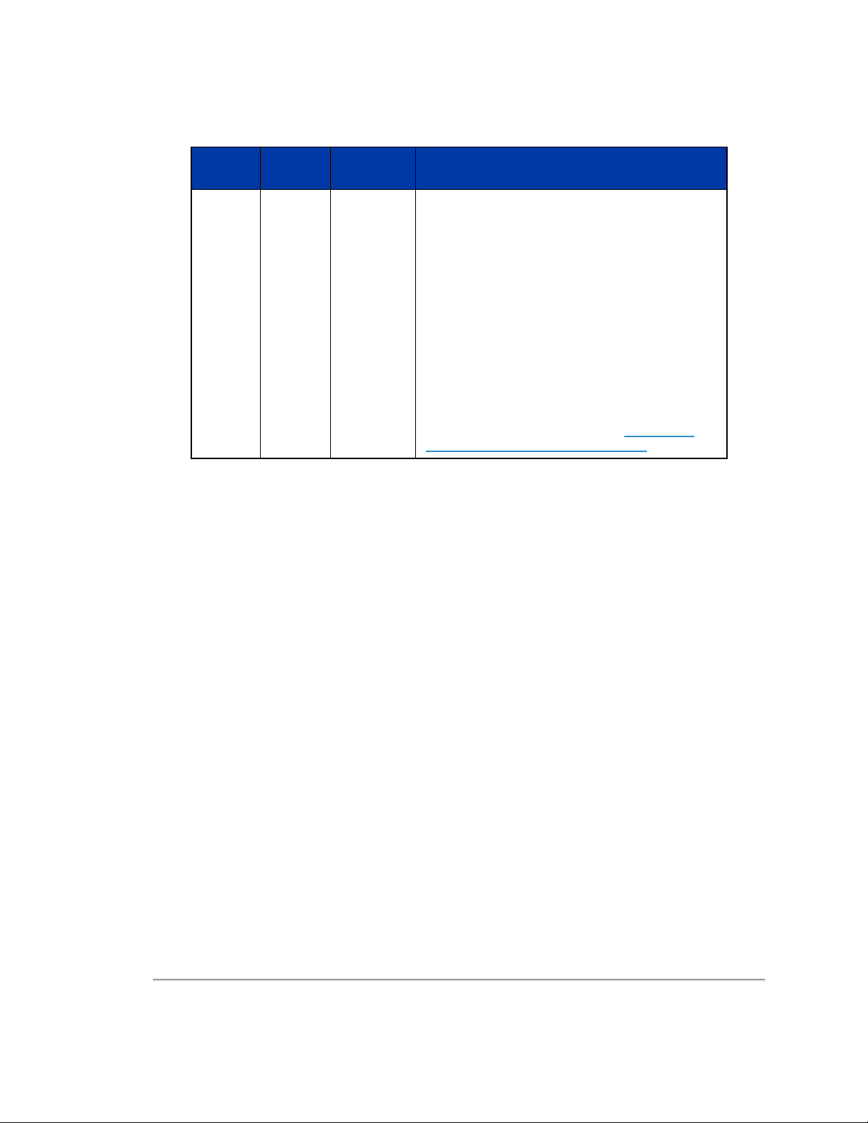
Table 1-1 Document Conventions
Convention Description
Bold
Italic
screen/code
[ ] square
brackets
{ } braces
| vertical bar
Indicates text on a window, other than the window title, including menus, menu options, buttons,
fields, and labels. Example: Click OK.
Indicates a variable, which is a placeholder for actual text provided by the user or system. Example:
copy
source-file target-file
Indicates text that is displayed on screen or entered by the user. Example:
# pairdisplay -g oradb
Indicates optional values. Example: [ a | b ] indicates that you can choose a, b, or nothing.
Indicates required or expected values. Example: { a | b } indicates that you must choose either a or
b.
Indicates that you have a choice between two or more options or arguments. Examples: [ a | b ]
indicates that you can choose a, b, or nothing. { a | b } indicates that you must choose either a or b.
Note: Angled brackets (< >) are also used to indicate variables.
16 VLP-16 User Manual

Note: Notes such as this indicate important information. They call attention to an operating procedure or practice which
may enhance user interaction with the product. Notes may also be used to prevent information loss or product damage.
Chapter 1 • About This Manual 17
Chapter 2 • VLP-16 Overview
This chapter provides basic information on the sensor's hardware and software components.
2.1 Overview
2.2 Product Models
2.3 Time of Flight
2.4 Data Interpretation Requirements
18
19
19
19
2.1 Overview
The VLP-16 sensor uses an array of 16 infra-red (IR) lasers paired with IR detectors to measure distances to objects. The
device is mounted securely within a compact, weather-resistant housing. The array of laser/detector pairs spins rapidly
within its fixed housing to scan the surrounding environment, firing each laser approximately 18,000 times per second,
providing, in real-time, a rich set of 3D point data.
Advanced digital signal processing and waveform analysis provide highly accurate long-range sensing, as well as calibrated reflectivity data, enabling easy detection of retro-reflectors like street-signs, license plates, and lane markings.
Combining 16 laser/detector pairs into one VLP-16 sensor and pulsing each at 18.08 kHz enables measurements of up to
300,000 data points per second -- or double that in dual return mode.
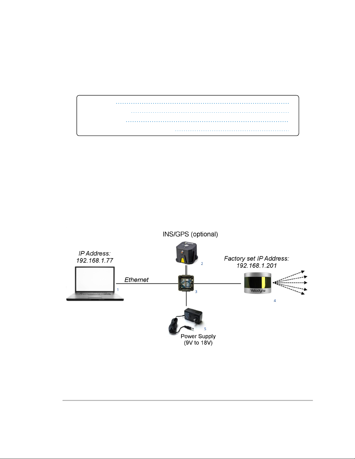
Figure 2-1 Example 3D Sensing System
18 VLP-16 User Manual

Table 2-1 3D Sensing System Components
Item Description
1 Desktop/Laptop Computer
2 INS/GPS Antenna/Interface (optional)
3 Velodyne Interface Box
4 Velodyne LiDAR Sensor
5 DC Power Supply
Note: Optional - not included unless ordered: Garmin GPS receiver (P/N: 80-GPS18LVC).
2.2 Product Models
For ordering information, contact Sales at http://www.velodynel idar.c om/c ontac ts.php.
2.3 Time of Flight
Velodyne LiDAR sensors use time-of-flight (ToF) methodology.
When each IR laser emits a laser pulse, its time-of-shooting and direction are registered. The laser pulse travels through
air until it hits an obstacle which reflects some of the energy. A portion of that energy is received by the paired IR detector,
which registers the time-of-acquisition and power received.
2.4 Data Interpretation Requirements
Desktop or Laptop computer
Advanced geo-referencing software application
GPS-Based
SLAM-Based
User Built
Purchased from System Integrator
For more software details, see
Note: Click the following link to view a list of Velodyne system integrators who can sell you imaging software or a complete
system: http://velodyneLiDAR.com/integrators.php.
Converting PCAP Files to Point Cloud Formats on page 66
.
Chapter 2 • VLP-16 Overview 19
Chapter 3 • Safety Precautions
This chapter provides information necessary for the safe operation of Velodyne LiDAR sensors.
Observe the following general safety precautions during all LiDAR sensor phases of operation. Failure to comply with
these precautions or with specific warnings elsewhere in this manual violates safety standards of intended sensor usage
and may impair the protection provided by the equipment. Velodyne LiDAR, Inc. assumes no liability for failure to comply
with these requirements.
3.1 Warning and Caution Definitions
3.1.1 Caution Hazard Alerts
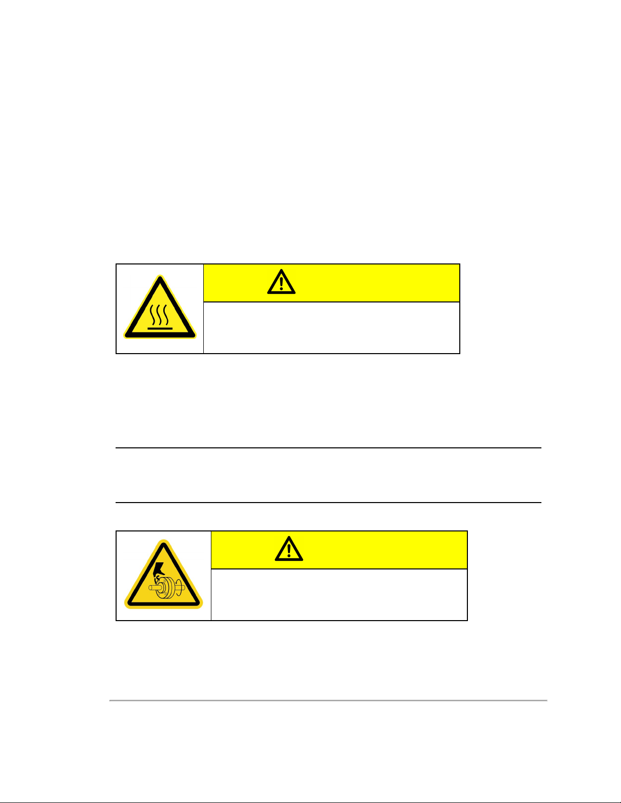
CAUTION
CAUTION indicates a potentially hazardous situation which may result in minor or moderate injury. It may also be used to alert against
unsafe practices. The icon shown in the left column displays the specific concern; in this case, a hot surface.
3.2 Safety Overview
3.2.1 Electrical Safety
Your sensor is powered by a 12 VDC (1.5 A-rated) power supply.
IMPORTANT: Read all installations instructions before powering up the sensor.
Note: The VLP-16 sensor is not field serviceable. For servicing and repair, the equipment must be completely shut off,
removed, packaged carefully, and shipped back to the manufacturer's facility with a completed RMA Form. See
and Maintenance on page 89
3.2.2 Mechanical Safety
for details.
Service
CAUTION
The VLP-16 sensor contains a rapidly spinning assembly. Do not
operate the VLP-16 sensor without its cover firmly installed. The
sensor does not contain user serviceable parts. It should not be
opened in the field.
20 VLP-16 User Manual
3.2.3 Laser Safety
This device complies with FDA performance standards for laser products except for deviations pursuant to Laser Notice
No. 50, dated June 24, 2007.
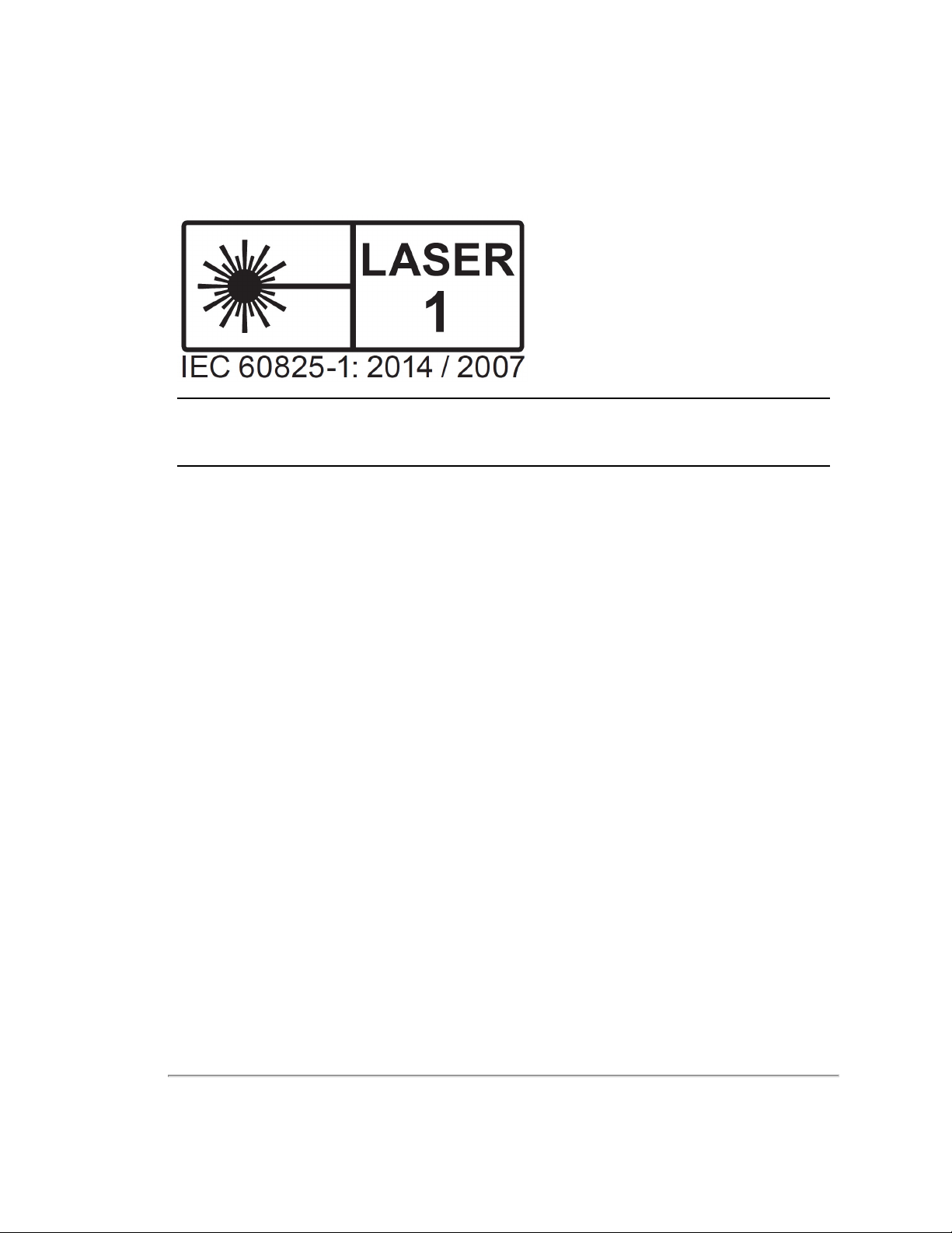
Figure 3-1 Class 1 Laser
Note: The VLP-16 sensor is a CLASS 1 LASER PRODUCT . The product fulfills the requirements of IEC 60825-1:2014
(Safety of Laser Products).
There are no controls or adjustments on the sensor itself that are user accessible.
Never look directly at the transmitting laser through a magnifying device.
Chapter 3 • Safety Precautions 21

Chapter 4 • Unboxing & Verification
This chapter provides the procedure to test and verify that your sensor is operating properly. Do this to check out a new
sensor before permanently mounting it somewhere.
4.1 What’s in the Box?
4.1.1 Variants
4.2 Verification Procedure
4.2.1 Network Setup in Isolation
4.2.2 Access Sensor’s Web Interface
4.2.3 Visualize Live Sensor Data with VeloView
22
22
22
23
24
26
4.1 What’s in the Box?
A standard Velodyne VLP-16 sensor comes packaged in its own cardboard box.
Ensure all the components are present:
VLP-16 sensor with a fixed 3.0 m data/power cable terminated inside its Interface Box
AC/DC power adapter and 1.8 m AC power cord (once assembled, this is the power cord)
1.0 m Ethernet cable
Velodyne USB memory stick, containing:
User Manual
VeloView application installers for PC, Mac, and linux
Sensor sample data (i.e. pcap files)
Miscellaneous documents
4.1.1 Variants
Variants of the sensor exist, particularly with other connector types and/or cable lengths, and even without an Interface
Box. Your sensor (or the type you are interested in) may vary from the standard configuration above. Contact Velodyne
Sales for details.
4.2 Verification Procedure
The purpose of this procedure is to verify the sensor’s basic functionality and get you started on your way to processing
sensor data in (or from) the field. It involves one computer and one sensor in isolation at a workbench or desk. You’ll need
AC power. You won’t need a GPS receiver.
A video of the VLP-16 installation process is on YouTube at the following location: https://www.y-
outube.com/watc h?v =Pa-q5el S_nE.
22 VLP-16 User Manual

Note: Due to the large volume of data produced by the sensor when scanning, users are cautioned against connecting it
to a corporate network.
1. Unpack the sensor and its accessories, and place them on a workbench or desk. Ensure the sensor is upright with
clear space around it.
2. Create a simple network setup with a test computer and the sensor in isolation. Follow the procedure in
Setup in Isolation below
3. Use the sensor’s Web Interface to perform basic sensor configuration. Follow the procedure in
Web Interface on the next page
4. Use VeloView (or other visualization software of your choice) to view data streaming from your sensor. Follow the
procedure in
When finished, the sensor should be ready for more complicated usage scenarios.
Visualize Live Sensor Data with VeloView on page 26
.
.
.
Network
Access Sensor’s
4.2.1 Network Setup in Isolation
Your sensor’s IP address comes from the factory set to its default value, 192.168.1.201. This procedure prepares a computer to communicate directly with the sensor at that address.
Note: If using the computer’s main Ethernet port, disconnect it from whatever network it’s on. If using a secondary Ethernet interface, the primary network cannot be a 192.168.1 network. If it is, use the primary Ethernet interface instead.
1. Open the computer’s Network Connections page.
2. Open the applicable Ethernet adapter and make sure the interface is enabled.
3. Open Properties > Internet Protocol Version 4 (TCP/IPv4) (
4. Select the Use the following IP address : function.
5. Make up an IP address for the Ethernet port and enter it: 192.168.1.XXX.
“XXX” may be any integer from 2 to 254 except 201.
6. Enter the subnet mask: 255.255.255.0.
When using a Windows-based computer, you can press the TAB key and the subnet mask field will automatically
populate with the default mask for the network class indicated by the IP address entered; which is 255.255.255.0 in
this case.
Figure 4-1 on the next page
).
Chapter 4 • Unboxing & Verification 23
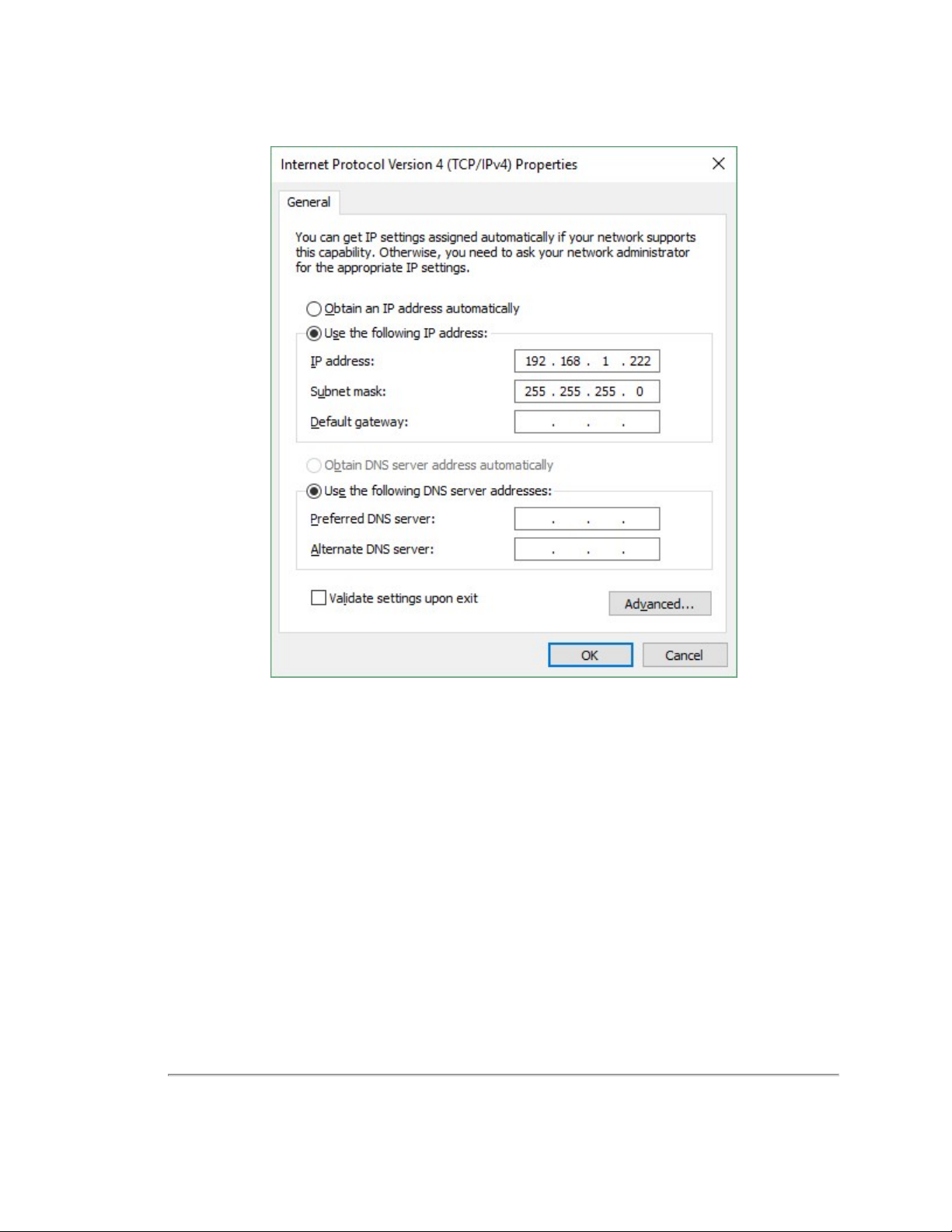
Figure 4-1 Sensor Network Settings
7. Click OK. Gateway and DNS are not necessary when testing in isolation.
In some cases it may be necessary to disable the computer’s firewall or configure it to allow UDP I/O on that Ethernet interface. How to do this is not covered here as the process varies widely.
4.2.2 Access Sensor’s Web Interface
Now the computer is ready to connect to the sensor.
1. Plug the Ethernet cable into the computer and then plug its other end into the Ethernet port on the sensor’s Interface Box.
fuse.
Figure 4-2 on the facing page
shows the Interface Box, its external ports, internal sensor terminal, and
24 VLP-16 User Manual
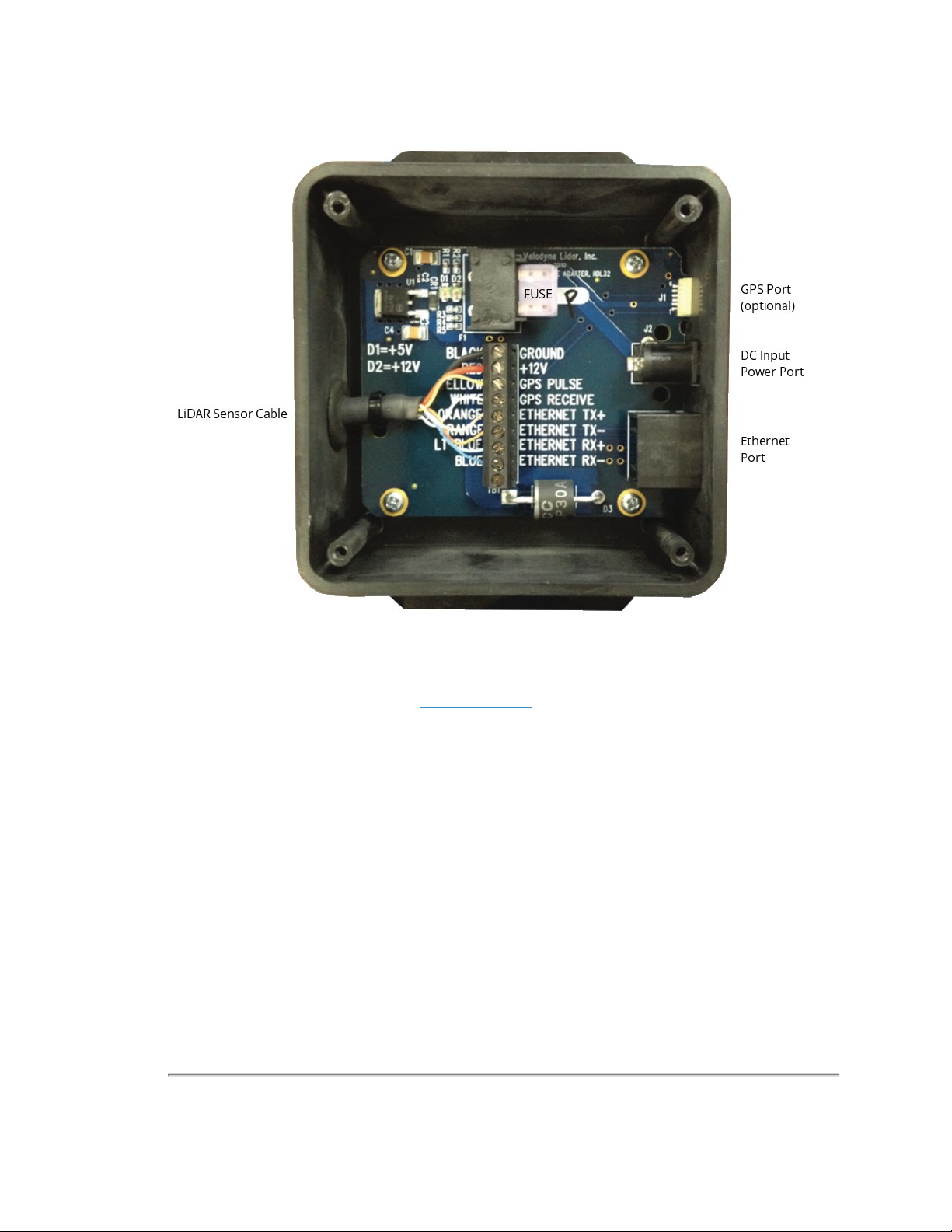
Figure 4-2 Interface Box (power and data connections)
2. Connect power to the sensor’s Interface Box.
When power is applied, two green LEDs in the Interface Box light up. The sensor begins scanning its environment
and transmitting data approximately 30 seconds after power up.
3. On the computer, point a browser to http://192.168.1.201.
4. The sensor’s Web Interface should appear (
The Web Interface provides access to many of the sensor’s control settings. See
details.
Figure 4-3 on the next page
).
Web Interface on page 68
for
Chapter 4 • Unboxing & Verification 25
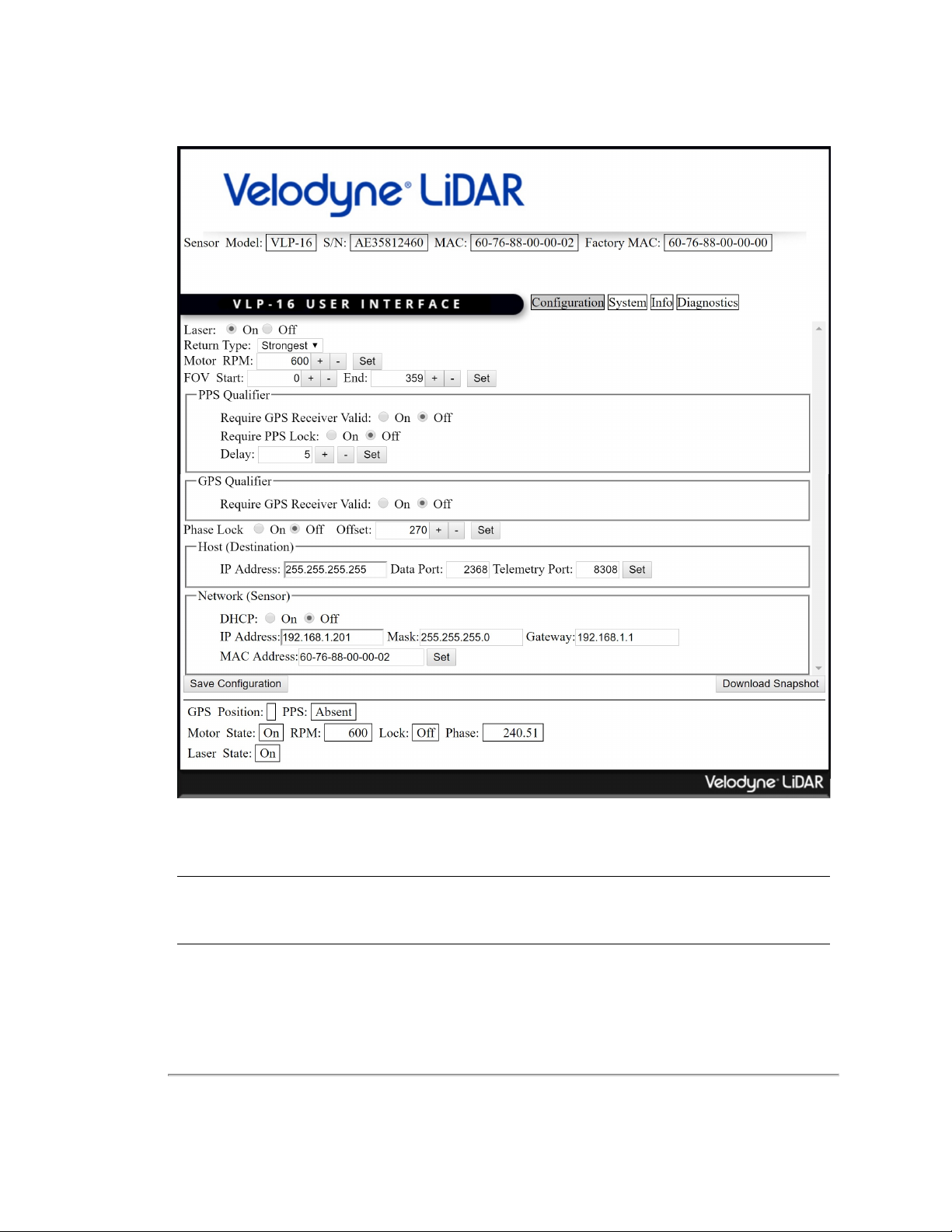
Figure 4-3 Sample Web Interface Main Configuration Screen
4.2.3 Visualize Live Sensor Data with VeloView
Now that the computer can access the sensor’s Web Interface, it’s time to get a first look at the sensor’s data.
Note: VeloView is an open source visualization and recording application tailored for Velodyne LiDAR sensors. Other
visualization software (e.g. ROS, DSR and PCL) can perform similar functions and may be used instead.
VeloView is documented in more detail in
the procedure detailed in
by following the procedure.
Install VeloView on page 112
VeloView on page 111
. Older versions should be updated to at least the version installed
. If the application isn’t already on the computer, perform
26 VLP-16 User Manual
4.2.3.1 VeloView Operation
1. Power-up the sensor.
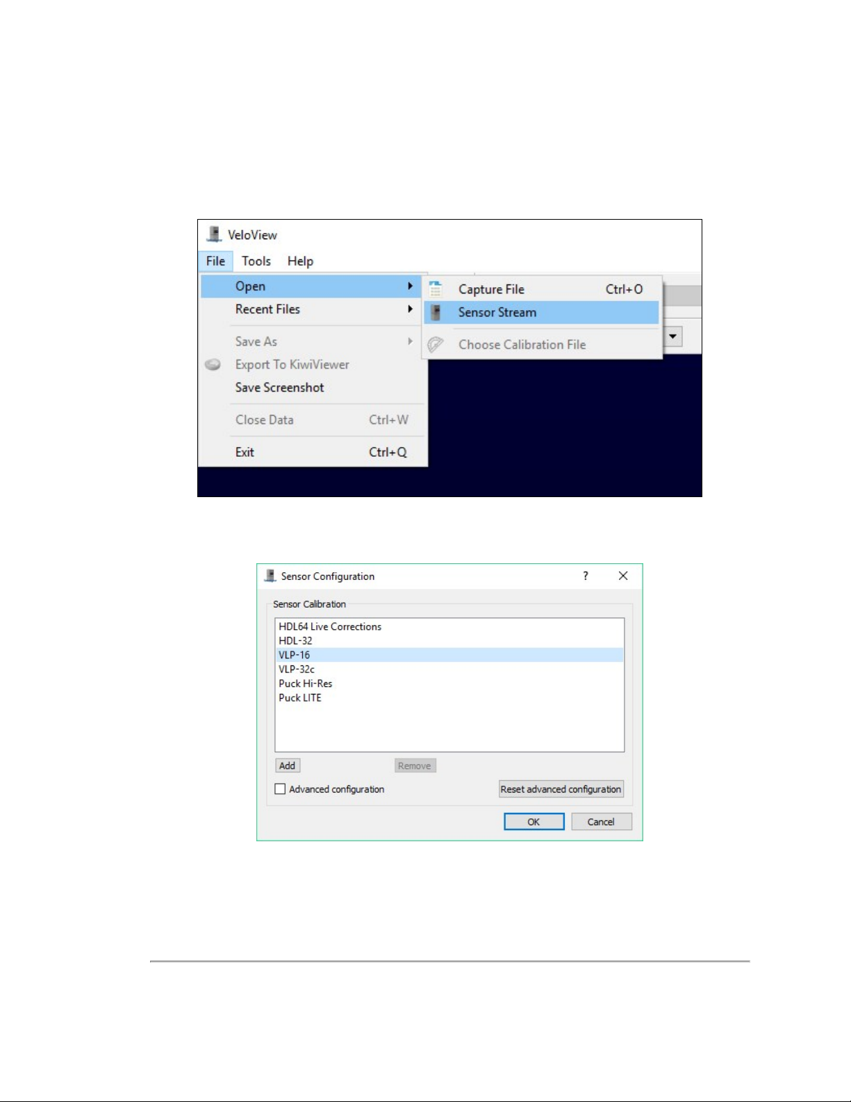
2. Start the VeloView application.
3. Click on File->Open and select Sensor Stream (
Figure 4-4 VeloView Open Sensor Stream
Figure 4-4 below
).
4. The Sensor Configuration dialog will appear (
Figure 4-5 VeloView Select Sensor Calibration
5. VeloView begins displaying the sensor data stream. See
Figure 4-5 below
). Select the correct sensor type then click OK.
VeloView Sensor Stream Display on the next page
.
Chapter 4 • Unboxing & Verification 27
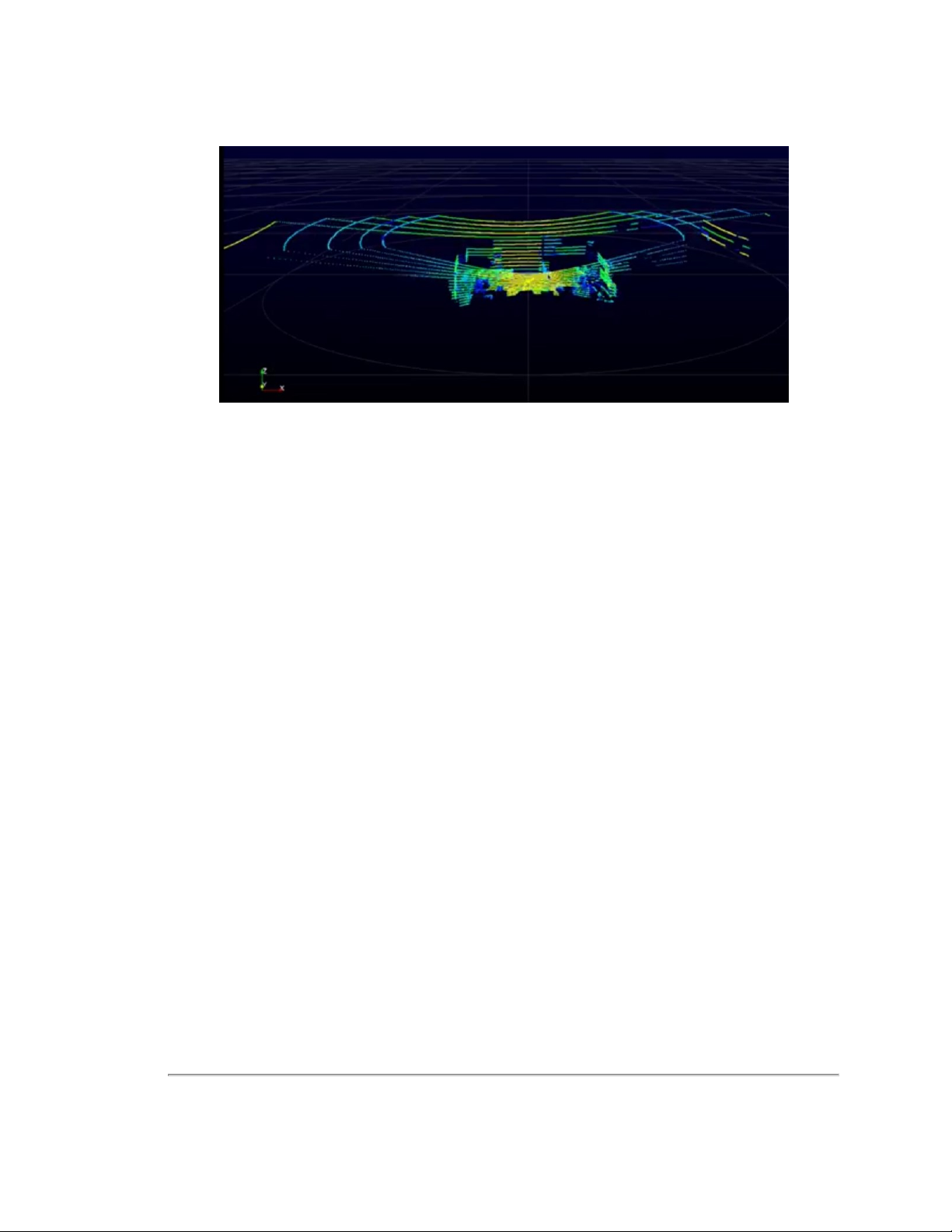
Figure 4-6 VeloView Sensor Stream Display
Above is an example of a VeloView screen in an office, workbench or lab scenario.
28 VLP-16 User Manual

Chapter 5 • Installation & Integration
This chapter provides important information for integrating the VLP-16 sensor into your application environment.
5.1 Overview
5.2 Mounting
5.3 Encapsulation, Solar Hats, and Ventilation
5.4 Connections
5.4.1 Integrated Cable and Interface Box
5.4.2 Operation Without an Interface Box
5.4.3 Power
29
29
30
30
31
31
31
5.1 Overview
Ensure the sensor is functional first before beginning sensor integration. See
Common steps in installation and integration involve:
Securely mounting the sensor to a vehicle, drone, robot, or other scanning platform
Allowing for proper ventilation, providing thermal protection, and sensor encapsulation
Connecting power to the sensor
Connecting the sensor's Ethernet data output to a computer, switch, or network – see
page 134
Optionally, connecting a GPS receiver or INS (Inertial Navigation System) – see
and NMEA GPRMC Message on page 41
The typical sensor setup uses a standard computer or laptop connected to the sensor. However, it is recommended to use
at least a 100 Mbps Ethernet adapter to accommodate the sensor data rate.
Verification Procedure on page 22
Network Configuration on
GPS, Pulse Per Second (PPS)
.
5.2 Mounting
The sensor base provides one ¼”-20-threaded, 9/32"-deep mounting hole, and two precision locating holes for locator
pins (
Figure 5-1 on the next page
best at 0° inclination (i.e. level to ground) as reductions to bearing life may occur at other orientations.
Ensure the sensor is mounted securely to withstand vibration and shock without risk of detachment. The unit does not
need shock proofing. The unit is designed to withstand automotive G-forces (i.e. 500 m/s2 amplitude, 11 ms duration
shock and 3 G
5 Hz to 2,000 Hz vibration).
RMS
Chapter 5 • Installation & Integration 29
). The sensor may be mounted at any angle or orientation, though reliability should be
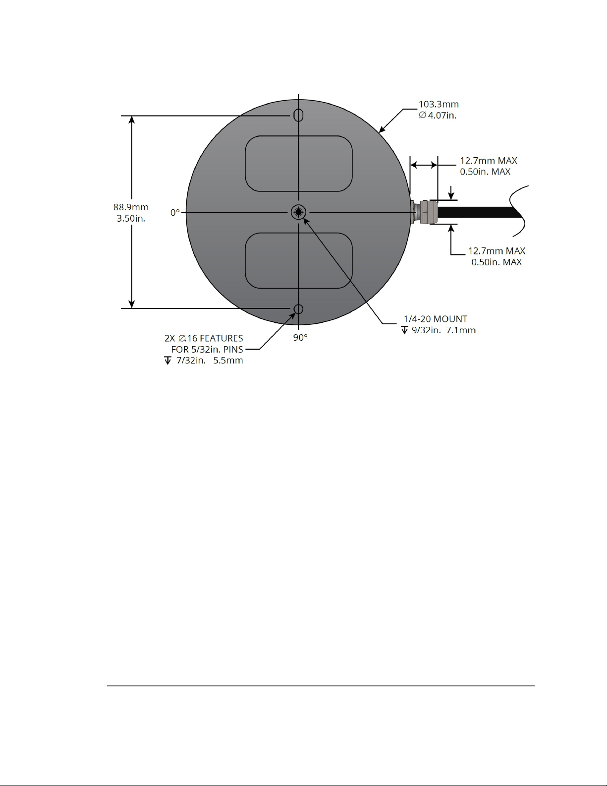
Figure 5-1 Mounting Details
5.3 Encapsulation, Solar Hats, and Ventilation
For various reasons, you may wish to encapsulate the sensor, either wholly or partially. The working field of view, if
covered with transparent material, should be highly transmissive of near-IR light at and near the 903 nm wavelength. Any
moisture that enters should have a way to drain passively.
The VLP-16 generates a moderate amount of heat during normal operation. Strategies for managing heat in hot weather
include employing a "thermal hat," exposing the sensor to moving air, and drawing heat from the sensor with a heat sink
(e.g. aluminum plate(s)).
The sensor reports internal temperatures passively on its web interface. The same readings may be obtained programmatically via curl commands (i.e. http GET requests). See
sensor's operating temperature range can be found on its data sheet.
Do not operate the sensor without sufficient ambient air flow or cooling.
Sensor Communication on page 68
for details. The
5.4 Connections
This section covers the sensor’s physical connections.
See
Network Considerations on page 135
work. See
nection.
Ethernet and Network Setup on page 134
before connecting one or more Velodyne LiDAR sensors physically to your net-
for instructions on how to configure the sensor's Ethernet con-
30 VLP-16 User Manual
 Loading...