

Velodyne VA-81OX, VA-1012X Owner's Manual

Specificaii"ons for Velodyne VA-81
OX
and VA-1
012X
, J
VA-81OX
VA-l012X
Cabi
net (inc.
legs)
14.75" (w)
17.15"
(w)
15.50" (h)
18.05" (h)
14.68" (d)
17.18"(d)
Hi
Pass Crossover
85 Hz (fixed)
85 Hz (fixed)
6 db per octave
6
db
per octave
Low
Pass Cr
ossover
6 db per octave
6 db per octave
24
db ultimate
24 db ultimate
Amplifier
Class Al B
Class AlB
65 watts
RMS
80
watts RMS
200 watts
peak
240
watts peak
Frequency
Response
35-85 Hz
28-85 Hz
Woo
fer
8 inches
10 inches
Forward firing
Forward firing
Magne
t
53
ounces
55 ounc es
Voice Co
il
2"
2"
Passive Radia t
or
10"
12"
Down firing
Down firing
Inputs
Line level
Li
ne level
Speaker level
Speaker level
Outputs
Line level
Line level
Speaker level .
Speaker
level
Warranty
One year
One year
(parts
& labor)
(parts
& labor)
Weight
44 Ibs. (approx.)
58
Ibs. (approx.)
Specifications subject to change without
not
ice.
t:D.
Printed in the U.S.A. on recycled
paper
.
\5C)
PIN:
63·8' OX Rev
. A $2.50
~SERIES
Owner's Manual
Mode
ls VA-81OX & VA-1012X
Velodyne
AudioNideo
Subwoofer
System
1-
While
it
is rec
ommended
that
the
subwo
ofer be pla ced on
the
same
plan
e as
the sate
llit
e speakers, room and system cond
iti
ons oft en
dictate otherwi
se. See yo
ur dea
ler for he
lp
in placemen
t.
Whe n using a pa
ir
of VA-X Subwoofers in stereo.
it
is preferab le to
place each subwoofer a
dj
acent to the sate
llit
e of t he same chann el.
Keep in
mind
that
frequency response and o
utput
level can be great-
ly
influence
d by placeme
nt
depe
ndin
g on the acoustic properti
es
of
the li ste
nin
g room. Typicall
y,
th e VA-X Subwoofer w
ill
sound louder
n
ex
t to a wall or in a corne
r.
Caut
ion!
The VA-X Series Subwoofer amplifier is built into the subwoofer cabinet. Do not
pl
ace the cabinet next
to
sources
of
heat such as furnace registers,
etc.
The
power
cord should
be
routed in such a way that it will not be walked on, pinched,
or
compressed.
Rega
rdless of where you install your VA-X Sub
woo
fer, it
must
remain
in an up
ri
ght position (passi
ve radiato
r Facing
downwa
rd) . Usi
ng.
shi ppin
g,
or
otherw i
se
storing t he VA-X Su
bwoo
fer in any
other
posi-
tion for an extended per
iod
of
time may cau
se
the passi
ve radiato
r
suspension to perma nently
defo
rm.
The VA-X Subwoo fer's drive
r h
as
been magnetically shielded
to
reduce
magnetic
emissio
ns from its cabinet. However, th is shie lding
m
ay
not
be adequate for al l install
atio
ns. Large-screen televisi
ons
are particularly sensitive
to
stray mag netic fields. If
your
te levision
produces distort
ed
colors after in
stallat
ion
of
your VA-X Subwoofer,
increase the distan
ce
between
your VA-X Su
bwoo
fer and television
u nti
I norma I coloration is atta i ned
Controls
The con
tro
l panel on th e back o f yo
ur
VA-X Seri
es
Subw
oofe
r
includes a powe r
sw
itch and a level con
tro
l.
Th
e power switch
is
a rocker type
and
is located in the u
pper
right
posi tion of
the panel.
The subwoo
fer level control knob (upper
lef
t pos iti
on)
is used
to
adjust the vo
lum
e level of bass
inf
ormation in relation to the
mi
drange and treble frequenci
es.
We recommend that you begin lis-
tenin g with
th
e level set at the point midway between MAX IMU M
(full
y clockwise) and
MINIMUM
(full
y co
unt
er-clockwise). Play
several
se
lectio ns of mu sic and vary the
subwoofe
r level
until th
e bass
match
es the
mid
s and highs to your sati sfaction. On
ce
you set th e
subw
oo
fer leve
l.
si
mply u
se your
system's main volum
e co
ntr
ol to
ma
int
ain consistent bass.
Velodyne
Owner's Manual
VA-X Series
Subw{)ofer System
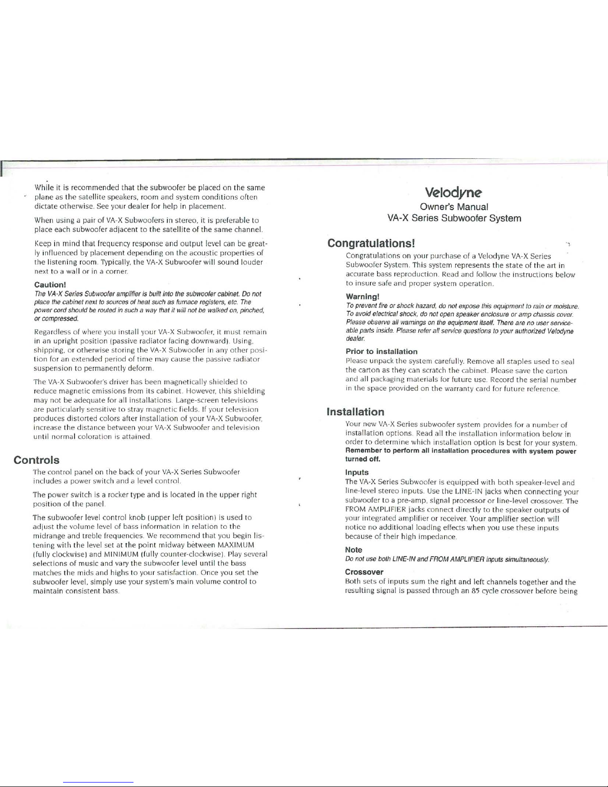
Congratulations!
..
~
Congra
tulati
ons on yo
ur
pur
chase of a Velodyne VA-X Seri
es
Subwoo
fer System . Thi s system represents t he state
of the art in
acc
ur
ate b
ass rep
roduction. Read a
nd
foll
ow the instructions below
to ins
ure sa
fe and
prope
r system operation.
Warning!
To
prevent fire or shock hazard, do not expose this equipment to rain
or
moisture.
To
avoid electrical shock, do not open speaker enclosure
or
amp
chassis cover.
Please observe all warnings on the equipment itself. There are no user serviceable parts inside. Please refer all service questions
to
your
authorized Velodyne
dealer.
Pr
ior
to installation
Pl
ease unpack the system carefully. Remove a
ll
staples
used
to
seal
the
carton as
they can scratch
the
cabinet. Please save the carton
and all packaging
materials for futur
e u
se.
Record the seria l number
in the space prov ided on the
warran
ty card for futu
re
referen
ce.
Installation
Yo
ur
new VA-X Seri
es
subwoo
fer system provides fo r a n
umbe
r of
i
ns
tall ation
opt
ions Read all the installat ion inform ation
below
in
order
to
dete
rmine which insta ll ation option is best for yo
ur
system.
Remember
to
perform
all
installation procedures with
system
power
turned off
.
I
npu
ts
Th
e VA-X Seri
es
Subwoo
fer is e
qui
pped wi
th both
speaker-level and
line-level stereo inputs. U
se
the LINE-IN jacks when co nnectin
g yo
ur
subwoo
fer to a pre-amp, signal processor or
lin
e-level crossove
r. The
F
ROM
AMPLIFIER jacks con nect
dir
ectly to the speaker output
s of
yo
ur
integ rated
amp
lifier or receiver. Your
amp
lifi
er
sectio
n wi
ll
noti
ce
no
add
itional loading effects when yo u u
se these inputs
becau
se
of th eir high impedan
ce
Note
Do not use both LINE-IN
and
FROM AMPLIFIER inputs simultaneously.
Crossover
Bo
th sets of inputs sum the rig
ht
and left channels toge ther and the
r
es
ultin
g signal is passed th rough an 85 cycle crossover
befo
re being
 Loading...