

Velodyne ULD-15, ULD-18 Owner's Manual
Velodyne
OWNER'S MANUAL
ULD-15, ULD-18
Series
II
Subwoofer Systems

•
For Y
our
Records:
Serial Numb
er
____________
_
Date
of
Purchase _
___
_______
_
Name of Store
__
_____
___
__
_
OWNER'S MANUAL
VELODYNE ULD-15 AND ULD-18
SERIES
II
SUBWOOFER SYSTEMS
Co
ngratulations
on
your purchase of a Velodyne ULD Seri
es II Subwooler System. This system represents the
state of the art in accura
te
bass reproduction. Read and follow the instructions below to insu
re
safe and proper
syst
em
operation. Regardless
of which installati
on conf
iguration you choose, please carefully read the entire
BASIC INSTALLATION section of this manual. Save this manu
al
for future referenc
e.
Wa
rning: To
prevent fire or shock hazard, do not expose this equipment to rain or moisture. To
avoid electrical shock do not open speaker enclosure or amp chassis cover. Please observe all
warnings
on
the equipment itself. There are no user serviceable parts inside. Please refer all
service questions to your authorized Velodyne dealer.
Ca
ution
: Risk
of
hazardou
s e
nergy
. Your ULD Subwoofer System has a very powerful ampli-
fier. Exercise extreme caution.
Do
not attempt a
ny
connection or disconnecti
on
with power on.
In
spect speaker lead connections at controller a
nd
woofer terminal plat
e.
Loose strands or frayed
wire can cau
se
a dangerous shor t circuit. Keep connections out of reach of children.
Prior
To Insta
llation
: Your ULD Subwoofer Syst
em
includes the following Ihree separate components:
1
~
A cabinet incorpora ting the bass driver, servo interface jack, and speaker terminals. Observe the
above caution notice.
2) A servo
controller which includes the High Gain Servo corr
ection circuitry. a 400 watt RMS
amplifier. high and low pass crossovers, input and output jacks, level control. servo interface jack.
and speaker terminal
s.
Observe the above caution notice.
3)
Cable kit with 25' phono cable for connection from controller to woofer cabinet, and a 3' pat
ch
cord for connecting the controller to your pre-amp. Speaker wire is not included.
Please unpack the system carefull
y.
saving t
he
carton and all packaging materials for future use. Remove all
staples used to seal the carton as they can scratch the cabinet.
BASIC INSTALLATION
(Refer to Figure
1)
System Connection: The servo controller is designed to be installed between your pre-amplifier and amplifier
(or between the amp and pre-amp sections of a receiver or integrated amp). Make all connections with the servo
controller unplugged.
1)
Install the includ
ed
3'
patch cord between your pre-amp's output jacks and the servo controller
(use FROM PRE AMP jacks).
2) Install a second patch cord between the servo controller (use TO POWER AMP jacks) and your
amplifier's input
Jacks.
- 1-
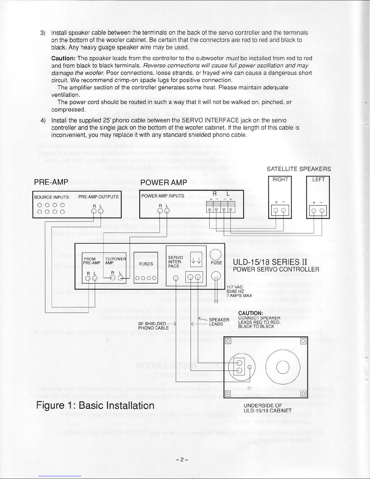
3)
Install speaker cable between the terminals on the back
of
the servo controller and the terminals
on the bottom of the woofer cabinet. Be certain th
at
the connectors are red to red and black
to
black. Any heavy guage speaker wire may be used.
Caution:
The speaker leads from the controller to the subwooler must be installed from red to red
and from black to
black terminals. Reverse connections will cause full
power
oscillation
and
may
damage the woofer.
Poor connections , loose strands, or frayed wi
re
can cause a dangerous short
circuit. We recommend
crimp·on spade lugs for positive connection.
The amplifier section
of
the controller generates some heat. Please maintain adequate
ventilation.
The power cord should be routed
in
such a way that
it
will not be walked on, pinched, or
compressed.
4)
Install the supplied 25' phono cable between the SERVO INTERFACE jack on the servo
controller and the single jack on the bottom of the woofer cabinet.
If
the length of this cable
is
inconvenient, you may replace it with any standa
rd
shielded phono cable.
SATELLITE SPEAKERS
PRE-AMP
SOURCE INPUTS
PRE'AMP
OUTPUTS
0000
0000
POWER AMP
POWER
AMP
INPUTS
R L
+ - - +
R l
RIGHT
LEFT
. -
. -
19
I
FROM
TO
POWE
PRE·AMP
AMP
FUSES
SERVO
~
,
0
INTER·
ow
ow
FUSE
FACE
I
e"
l
--Dc).
0000
I
~:o
l
c;;
ULD-15/18 SERI
ES
II
POWER SERVO CONTROLLER
L
--=t
+====
=--====-J:~
~~=!~
-
ll-
J
117 VAC
50160
HZ
25' SHIELDED
:---l
PHONO CABLE
Figure
1:
Basic Installation
-2-
7 AMPS MAX
?-
SPEAKER
~LEADS
CAUTION:
CONNECT SPEAKER
LEADS
RED
TO
REO
.
BLACK
TO
BLACK
I~
[-i-,
\
-"-
UNDERSIDE OF
ULD -15/18 CABINET
•
•
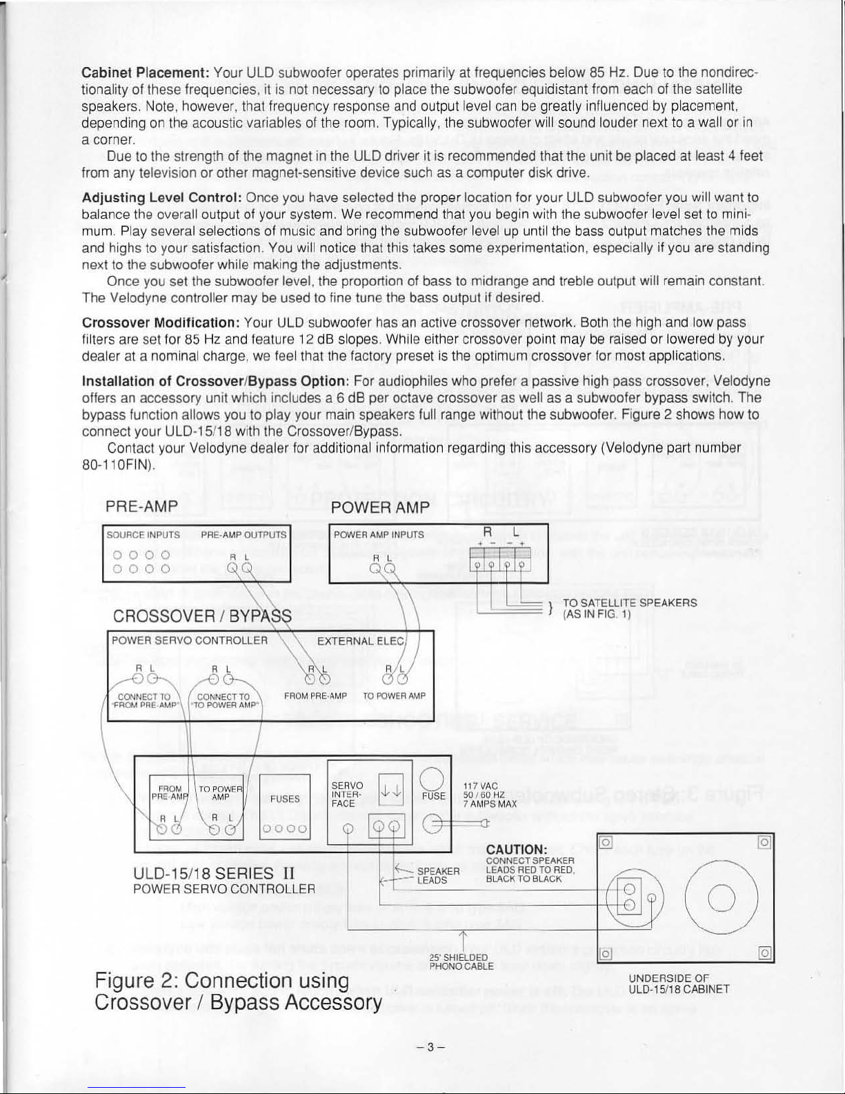
Cabinet Placement : Your ULD subwooler operates primarily
tionality of these frequencies.
speakers. Not
depending
a corner.
Due
trom any television or other magnet-sensitive device such as a computer disk drive .
e.
however. that frequency response and outp
on
the acoustic variables
to
the strength of the magnet in the ULD driver it is recommended that the un
it
is not necessary
of
the room. Typically. the subwoofer will sound louder next to a wall or
to
place the subwoofer equidistant from each of the satellite
at
Irequencies below
ut
level can be greatly influenced by placement.
8S
Hz. Due to the nondirec-
it
be placed at least 4 teet
in
Adjusting
balance the overall outpu
mum. Play sever
and highs to your satisfaction.
;
next to the subwooter while making the adjustments.
Once you set the subwoofer level. the proportion of bass to midrange and treble outpul will remain conslant.
The
Crossover
filte
rs
dealer at a nominal charge. we feel that the facto
Ins
tallation
offers an accessory unit which includes a 6 dB per octave crossover as well as a subw
bypass function allows you to play your main speake rs full range without the subwoofe
co nnect your ULD-15/18 with the Crossover/Bypas
Conta
80-1
PRE-AMP
SOURCE INPUTS PRE ·AMP OUTPUTS
Level Co
Velodyne controller may be used to tine tune the bass output if desired.
Modification
are set for
of
ct
your Veladyne dealer for additional information
10FIN
).
0000
000
0
ntrol
: Once you have selected the proper location tor your ULD subwooter you will want to
t at your system. We recommend that you begin with the subwoofer level set
al selections
: Your ULD subwoofer has
8S
Hz and feature 12
Crossover/Byp
A
);,
'-S..~
of
music and bring the subwooter level up until the bass output matches the mids
You will
ass
notice that this takes some experimentation, especially
an
active crossover network. Both the high and low pass
dB
Option
POWER
slopes. Whi
: For audiophiles who prefer a passive high pass crossover, Velodyne
POWER
le either crossover point
ry
preset is the optimum crossover for most applications.
s.
reg
arding this accessory (Velodyne part numbe r
AMP
AMP INPUTS
R L
, ,
it
you are standing
may
be raised or lowered by your
ooter bypass switch. The
r.
Figure 2 shows how to
to
mini-
CROSSOV
POWER SERVO CONTROLLER
ER
/
B
~
RL
FROM
fORE·AMP 10
EXTERNAL
ELE
!'OWER AMP
II
FROM
PRE
ULD-
POWER SERVO CONTROLLER
Figure
TO POWE
AM AM
15/
2:
18
SERIES
P
FUSES
0000
II
Connection using
Crossover / Bypass Accessory
SERVO
INTERFACE
I
~
)
tic!
~
~
0 117
"" ""
t+=
FUSE 50 I
SPEAKER LEADS RED
_
"_'D
_' _ _ _ '_"'_
25' SHIELDED
PHONOCABLE
_I }
l
VAC
GO
HZ
7 AMPS MAX
CAUTION:
CONNECT SPEAKER
CI<
TO
f -
TO
BLACK
TO
SATELLITE SPEAKERS
(AS
IN
FIG 1)
RED.
--t
--==
IQ)
UNDERSIDE OF
ULD·15/
1S
CABINET
-
3-
 Loading...