

Velodyne OPTIMUM-8, Velodyne CHT 10, Velodyne CHT 8, OPTIMUM-10, OPTIMUM-12 User Manual
...Page 1
OpTIMUM
SERIES
QPTIMUM
QPTIMUM
QPTIMUM
..
8
..
10
..
12
USER'S
MANUAL
High
Output
Digital
EQ
Subwoofer
f~(
Velodyne
Page 2
IMPORTANT
SAFETY
INSTRUCTIONS
A
~
Caution
To
reduce
the
riskofelectric
qualified
The
within
The
(servicing)
1.
2.
3.
4.
5.
6.
7.
8.
9.
10.
11.
12.
13.
14.
15.
16.
17.
18.
19.
20.
21.
service
personnel.
lightning
Read
Retain
Heed
Follow
Water
sink,
Carts
the
WallorCeiling
the
Ventilation
ventilation.
ventilation
through
Heat
products
Power
instructionsoras
GroundingorPolarization
having
If
your
Power-Cord
by
pointatwhich
Cleaning
Nonuse
periodoftime.
Object
the
Damage
a.
b.
c.
d.
e.
Servicing
instructions.
personnel.
plugisdamaged,
to
Lightning
for
Overloading
inariskoffireorelectric
Attachments
Voltage
versionto230-voltsorvice-versa.
CAUTION:
flash
with
the
product's
exclamation
manufacturer.
manufacturer.
you
items
enclosure.
The
Objects
The
The
The
rainormoisture,
long
point
instructionsinthe
Instructions
Instructions
Warnings
Instructions
and
Moisture
laundry
tub,ina
and
Stands
-
For
openings;orplacedina
the
ventilation
-
The
product
that
produce
Sources
one
blade
are
unabletoinsert
electriciantoreplace
Protection
placed
-
The
Periods
and
Liquid
Requiring
power-supply
have
product
product
product
-
The
All
Servicingisrequired
-
For
periodsoftime,
-
-
-
Insure
To
prevent
arrowhead
enclosure
symbolisintendedtoalert
-
All
-
-
All
warningsonthe
-
-
wet
-
Mounting
The
product
example,
openings.
shouldbesituated
heat.
-
The
markedonthe
wider
uponoragainst
they
exit
product
-
The
Entry
Service
cordorplug
fallenorliquid
has
been
does
not
has
been
user
other
servicing
liquid
does
added
Do
not
Only
use
that
electrical
CAUTION
shock,donot
symbolisintendedtoalert
that
maybeof
literature
safety
The
safety
All
operating
The
product
basement,
The
-
shouldbesituatedsothat
the
product
product
-
This
than
the
the
plug
your
-
Power-supply
from
the
shouldbecleaned
power
cordofthe
-
Care
-
The
exposedtorain.
appeartooperate
droppedordamaged.
should
shouldbereferredtoqualified
has
been
not
operate
protection
unplugitfrom
overload
shock.
attachments
the
subwooferisonly
remove
sufficient
accompanying
and
operating
and
operating
product
and
use
should
nearaswimming
product
The
shouldbeconnectedtoa
product.
other).
obsolete
them,
product.
has
not
when
wall
shock,
should
product
should
built-in
installation
away
product
This
fully
into
outlet.Donot
cords
paying
product
shouldbetakensothat
product
has
been
been
spilled
attempttoservice
the
apparatus
spilledorobjects
normally,orhas
for
the
product
the
outlets,
and
This
will
match
cover
(or
back).Nouser-serviceable
the
usertothe
magnitudetoconstituteariskofelectric
the
usertothe
the
subwoofer.
instructions
instructions
andinthe
instructions
notbeused
shouldbemountedtoa
notbesituatedona
from
maybeequipped
plug
will
the
outlet,
shouldberoutedsothat
particular
onlyasrecommendedbythe
shouldbeservicedbyqualified
damaged.
into
normallyorexhibitsamarked
wall
outlet.
extension
accessories
connectedtothe
resultindamagetothe
wide
shouldberead
shouldberetained
operating
shouldbefollowed.
near
water-for
poolorthe
be
used
only
its
locationorposition
suchasa
heat
sources
power
withapolarized
fit
into
the
try
reversing
defeat
the
attentiontocordsatplugs,
shouldbeunplugged
objectsdonot
the
product.
the
product
service
has
been
damagedinany
have
fallen
into
been
dropped.
duringalightning
cordsorintegral
specifiedbythe
bladeofplugtowide
presenceofuninsulated
presenceofimportant
instructions
like.
withacart
bed,
sofa,
bookcaseorcabinet
suchasradiators,
supply
onlyofthe
power
outlet
the
plug.Ifthe
safety
purposeofthe
they
from
beyond
personnel.
the
apparatus,
stormorwhenitis
manufacturer.
rated
source
subwoofer
A
~
parts
inside.
shocktopersons.
operating
before
the
productisoperated.
for
future
reference.
shouldbeadhered
example,
wallorceiling
convenience
nearabathtub,
or
stand
onlyasrecommended
does
not
interfere
rug,orsimilar
alternating-current
only
are
not
manufacturer.
the
fall
service
changeinperformance.
whatisdescribedinthe
Refer
way,
voltage.Donot
and
slot,
fully
surface
that
may
impede
heat
registers,
type
describedinthe
one
way.
Thisisa
plug
should
polarized
likelytobe
convenience
outlet
when
and
liquids
personnel
suchasa
the
possible
when:
all
servicingtoqualified
power-supply
apparatus
left
unattended
receptaclesasthis
injurytothe
inserted.
~
\0'
Refer
"dangerous
and
maintenance
to.
washbowl,
recommended
with
that
may
the
stoves,orother
line
plug(aplug
safety
still
failtofit,
plug.
walkedonor
receptacles,
left
unused
are
not
spilled
has
been
and
connect
the
servicing
voltage"
kitchen
its
proper
block
flowofair
operating
feature.
contact
pinched
and
foralong
operating
service
cord
exposed
unused
can
result
120-volt
user.
to
by
by
the
the
onto
or
WWW.VELODYNE.COM
Optimum
User's
Manual
Page 3

TABLE
OF
CONTENTS
Congratulations .
Installation .
Front Panel Features .
Rear Panel Connections .
Rear Panel Connections - Detailed Explanation . . .
Interconnect Cables . . . . . . . . . . . . .
Usage . . . . . . . . .
Care of Your Subwoofer . .
Troubleshooting and Service . .
Specifications . . . .
Velodyne Products . . . . .
..
..
. .
. .
· 1
· 3
· 5
· 7
· 9
·
10
....11
·
·
·
·
15
15
16
18
WWW.VELODYNE.COM
Optimum
User's
Manual
ii
Page 4
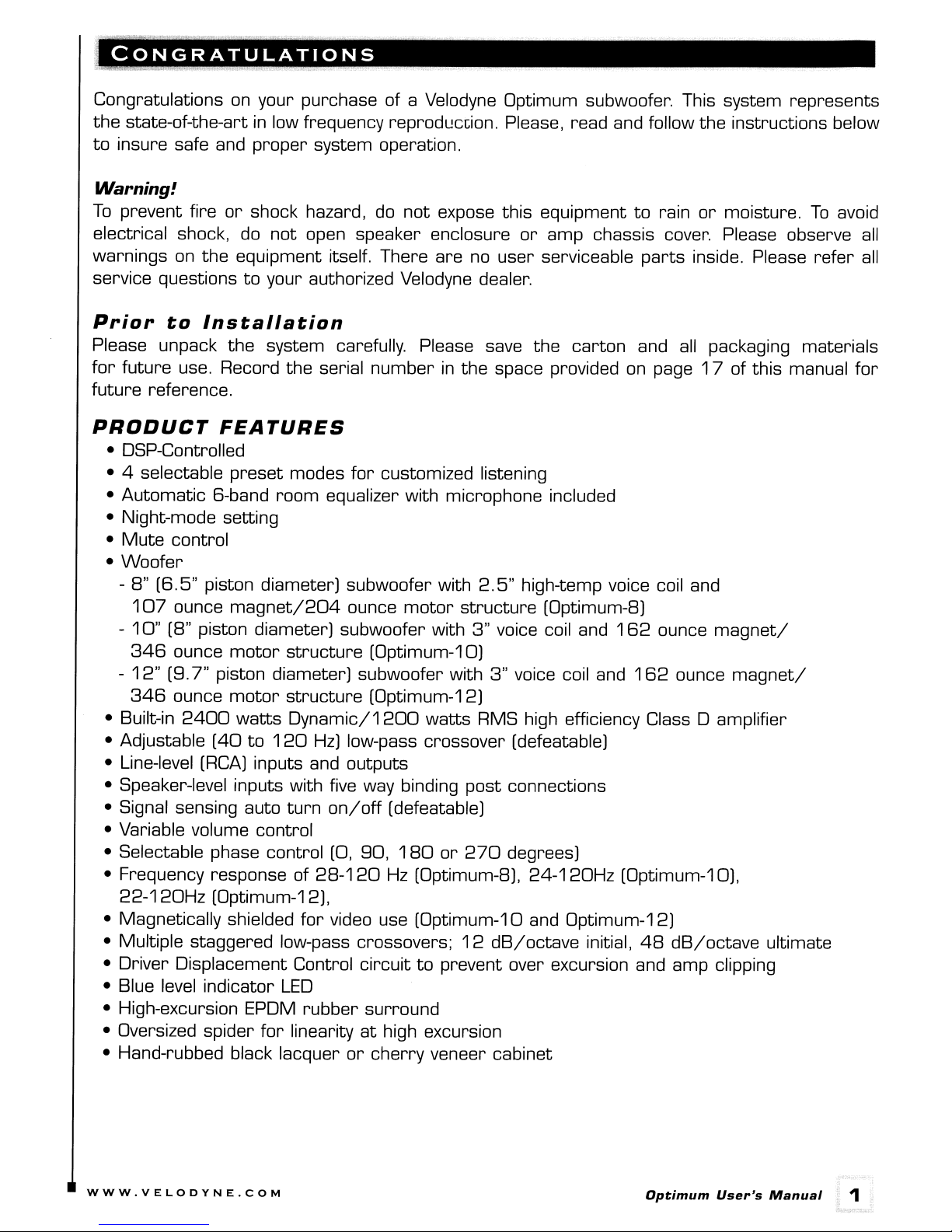
CONGRATULATIONS
Congratulations on your purchase of a Velodyne Optimum subwoofer. This system represents
the
state-of-the-artinlow frequency reprodL!ccion. Please, read and follow
to
insure safe and
Warning!
To
prevent fire
electrical shock, do
warnings
on
the
proper
or
shock hazard,
system operation.
do
not
not
open speaker enclosure
expose this equipment
or
amp chassis cover. Please observe
equipment itself. There are no user serviceable
to
parts
the
rain
or
moisture.
inside. Please
instructions below
To
avoid
all
refer
all
service questionstoyour authorized Velodyne dealer.
Prior
to
Installation
Please unpack the system carefully. Please save
for
future use. Record the serial
numberinthe space provided on page
future reference.
PRODUCT
FEATURES
• DSP-Controlled
• 4 selectable
preset
• Automatic 6-band
modes
room
for
customized listening
equalizer with microphone included
• Night-mode setting
Mute
•
Woofer
•
- 8"
-
-
• Built-in
• Adjustable
• Line-level
• Speaker-level inputs with five way binding
• Signal sensing auto
control
(6.5"
107
10"
346
12"
346
piston diameter) subwoofer with
ounce
magnet/204
ounce
(8" piston diameter) subwoofer with
ounce
(9.7"
ounce
2400
motor
structure
(Optimum-10)
piston diameter) subwoofer with
motor
watts
(40
(RCA)
structure
(Optimum-12)
Dynamic/1200
to
120
Hz)
low-pass crossover (defeatable)
inputs and outputs
turn
on/off
motor
structure
watts
post
(defeatable)
2.5"
3"
voice coil and
3"
RMS high efficiency Class 0 amplifier
• Variable volume control
90,
180
or
• Selectable phase control (0,
• Frequency response of
22-120Hz
(Optimum-12),
• Magnetically shielded
28-120
for
video use (Optimum-10 and Optimum-12)
Hz
(Optimum-8),
• Multiple staggered low-pass crossovers;
• Driver Displacement Control
• Blue level indicator
• High-excursion EPDM
• Oversized spider
LED
rubber
for
linearityathigh excursion
• Hand-rubbed black lacquer
circuittoprevent over excursion and amp clipping
surround
or
cherry
270
12
dB/octave
veneer cabinet
the
carton
and
high-temp voice coil and
(Optimum-8)
162
ounce
voice coil and
162
ounce
connections
degrees)
24-120Hz
(Optimum-10),
initial,
48
dB/octave
all
packaging materials
17
of this manual
magnet/
magnet/
ultimate
for
WWW.VELODYNE.COM
Optimum
User's
Manual
1
Page 5
Prepare
Your new Velodyne subwoofer provides
installation information below
system. Remember
to
prevent
for
Installation
to
perform
possible damage.
in
for
a number of installation options. Read
order
all
to
determine which installation option is best
installation procedures with system
Placement
The
first
stepininstalling your new Optimum sub istodetermine whereitwill be placedinthe
room. Unpack the system carefully and use the following guidelines
room placement option.
all
for
power
in
ordertofind the best
turned
of the
your
off
True subwoofers operate
Keep
in
mind
that
frequency response and output
placement, depending
output from your subwoofer,
greatest output levels and maximize low frequency extension. If
should
walls and close
be
placed along a wall. The
to
the center of your room.
a pair of Velodyne subwoofers
at
extremely low frequencies which are primarily omni-directional.
level
can
on
the acoustic properties of the listening room.
try
placingitwithin a foot of a corner. This location will offer the
at
worst
in
stereo,
location
Avoid
it
is preferable
for
a subwoofer is typically
these locations when possible.
to
feed each subwoofer with one
be
drastically influenced
all
possible, your subwoofer
channel and place each subwoofer near the satellite of the same channel.
on
Depending
possible. Finding the
experimentation.
best
to
you
Regardless of where
[woofer facing forward). Using, shipping
the size and type of furnishings
We
best
suggest
location within your environment will likely require some
you
experiment with the location during setuptofind what sounds
when seatedinyour typical listening position.
you
install your Velodyne subwoofer,itmust
or
extended period of time may resultindamagetothe unit
in
the room, perfect placement may
remaininan
storing the subwooferinany
not
covered
by
Caution!
This
subwoofer has electronics built into the cabinet.
of
heat
such as furnace registers, radiators, etc.
excessive moisture such as evaporative coolers, humidifiers, etc.
routed
result
in
such a way
in
damagetothe insulationorwire.
thatitwill
not
be walked
on,
00
not
place the cabinet nexttosources
00
not
place the unit
The
power
pinchedorcompressedinany way
To
obtain the best
far
away
upright position
other
position
warranty.
near
cord
from
When
not
for
sources
should be
that
by
any
using
be
an
of
could
Although the Velodyne Optimum-10 and the Optimum-12 are magnetically shielded,
Optimum-B subwooferisNOT
an
older
CRT
monitororTV,
distance
WWW.VELODYNE.COM
by
minimizing distortion of the picture and colors.
magnetically shielded. Should
keepitat
least two feet from the monitor. Experiment
you
find it necessarytouseitwith
for
Optimum
User's
Manual
the
correct
2
Page 6
INSTALLATION
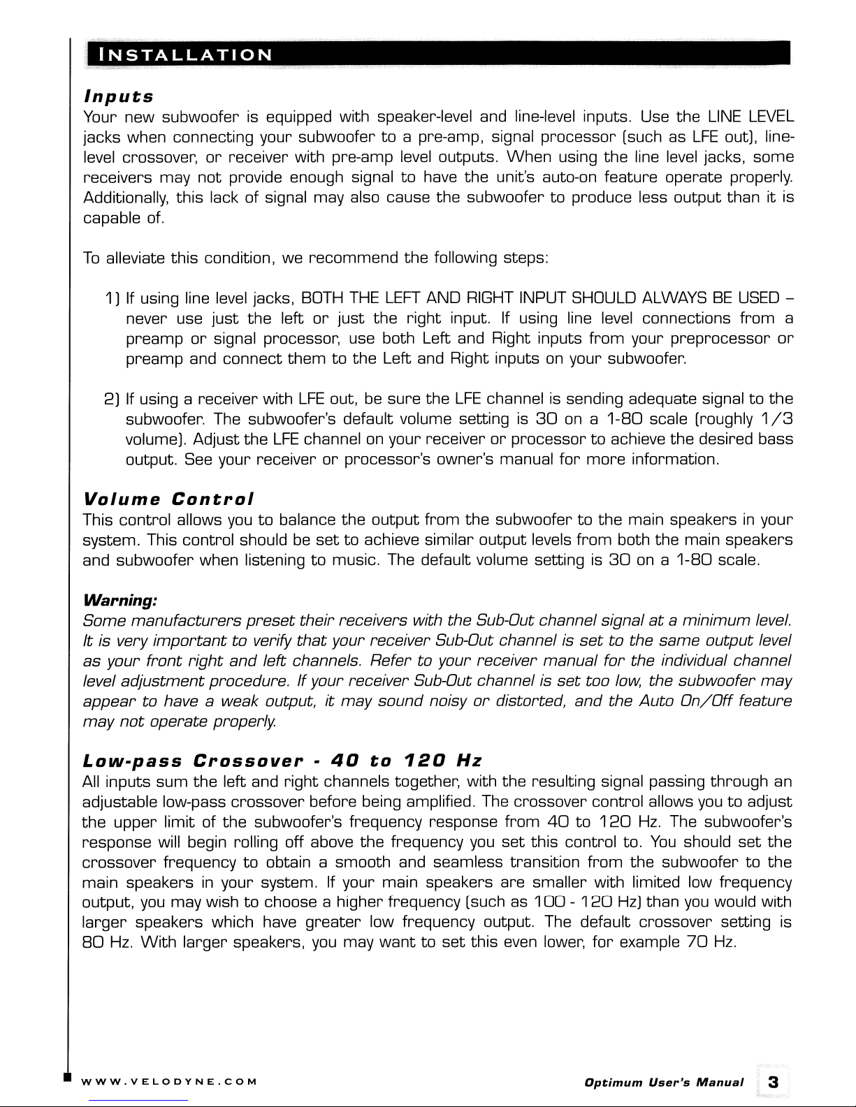
Inputs
Your new subwoofer is equipped with speaker-level and line-level inputs. Use
jacks when connecting your subwoofertoa pre-amp, signal
or
level crossover,
receivers may
Additionally,
this
receiver with pre-amp level outputs.
not
provide enough signal
to
have
lack of signal may also cause
the
unit's auto-on feature operate properly.
the
subwoofertoproduce less output thanitis
capable of.
To
alleviate
1) If using line level jacks, BOTH
never use
preamp
preamp
2) If using a receiver with
this
condition, we
just
or
signal processor, use both Left and Right inputs
and connect
the
recommend
left
or
them
LFE
out, be sure
just
to
the
following steps:
THE
LEFT
AND RIGHT INPUT SHOULD ALWAYS
the
right
the
Left and Right inputs on your subwoofer.
input. If using line level connections
the
LFE
channel is sending adequate signaltothe
subwoofer. The subwoofer's default volume setting is
volume). Adjust
output. See your receiver
the
LFE
channel on your receiverorprocessortoachieve the desired bass
or
processor's owner's manual
When
30
processor
[such as
using the line level jacks, some
on a
for
from
more
your preprocessor
1-80
scale [roughly
information.
the
LINE
LFE
BE
LEVEL
out], line-
USED
from
or
1/3
a
Volume
This control allows you
system. This control should
and subwoofer when listening
Control
to
balance
the
output
be
settoachieve similar output levels
to
music. The default volume setting is
from
the
subwoofertothe
main speakersinyour
from
both the main speakers
30
ona1-80
scale.
Warning:
Some
It
as
level
appear
may
Low-pass
All
adjustable low-pass crossover before being amplified. The crossover control allows you
the
response will begin rolling off above
crossover
main speakersinyour system. If your main speakers are smaller with limited low frequency
output, you may wish
larger
80
manufacturers
is very
your
important
front
adjustment
to
not
right
have a weak output,itmay
operate
procedure.Ifyour
Crossover
inputs sum
upper
speakers which have
Hz.
With
the
limit of
frequency
larger
preset
to
verify
and
properly
left and
the
subwoofer's frequency response
to
to
speakers, you may
their
receivers with
that
your
receiver Sub-Out channel is
left
channels.
-
right
channels together, with
Refertoyour
receiver Sub-Out channel is
sound
40
to
120
the
frequency you
obtain a smooth and seamless transition
choose a higher frequency [such as
greater
low frequency output. The default crossover setting is
wanttoset
the
Sub-Out channel signal
receiver manual
noisy
or
Hz
this even lower,
ataminimum
settothe
for
set
too
low,
distorted,
the
resulting signal passing through an
from
set
this control to.
40
and
the
to120
from
100-120
for
same
the individual channel
the subwoofer
Auto
Hz.
You
output
On/Off
The subwoofer's
should
the subwoofer
Hz)
than you would with
example
70
to
Hz.
level.
level
may
feature
adjust
set
the
to
the
WWW.VELODYNE.COM
Optimum
User's
Manual
3
Page 7
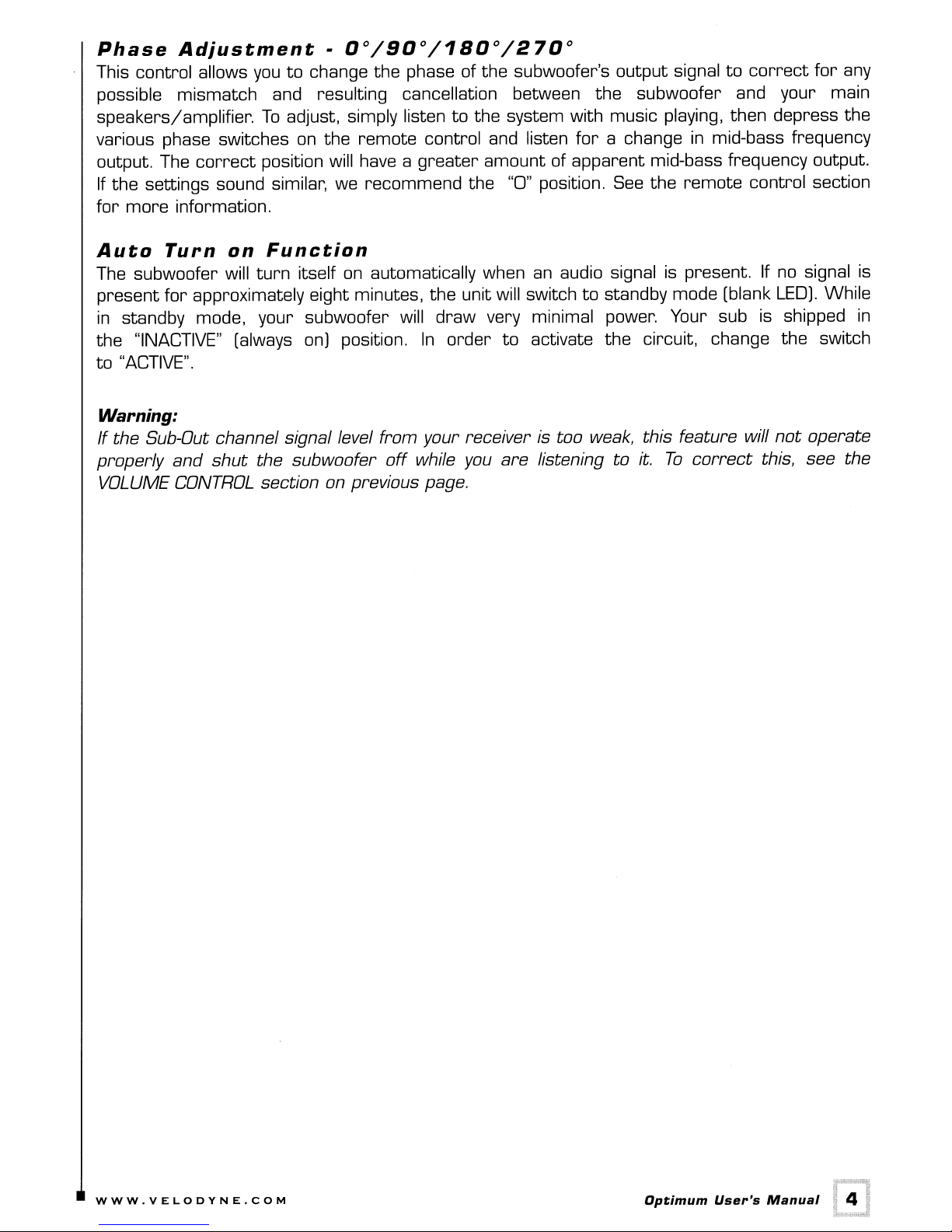
Phase
This control allows
possible mismatch and resulting cancellation between the subwoofer and your main
speakers/amplifier.
various phase switches
output. The
If
the settings sound similar, we recommend the "0" position.
for
more
Adjustment·
youtochange the phase of the subwoofer's output signaltocorrect
To
correct
information.
position will have a
0°/90°/180°/270°
for
any
adjust, simply listentothe system with music playing, then depress the
on
the remote control and listen
greater
amount of apparent mid-bass frequency output.
for
a changeinmid-bass frequency
See
the remote control section
Auto
The subwoofer will
present
in
the "INACTIVE" (always
"ACTIVE".
to
Turn
for
standby mode, your subwoofer will draw very minimal power. Your sub is shipped
on
Function
turn
itself
on
automatically when
approximately eight minutes, the unit will switchtostandby mode (blank
on)
position.
In
order
an
audio signal is present. If
to
activate the circuit, change the switch
no
LED).
Warning:
If the Sub-Out channel signal level from your receiveristoo
properly and
VOLUME
shut
CONTROL
the subwoofer
off
while
section on previous page.
you
are listening to
weak,
this feature will
it.
To
correct
not
this, see the
signal is
While
in
operate
WWW.VELODYNE.COM
Optimum
User's
Manual
4
Page 8
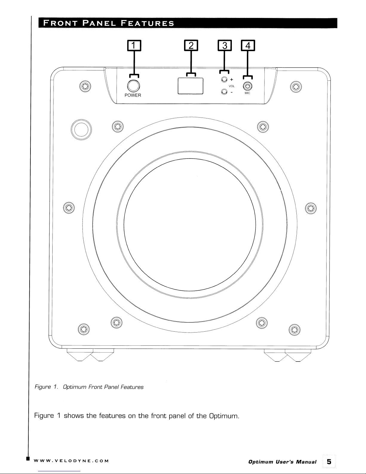
FRONT
PANEL
FEATURES
Figure
Figure 1 shows
WWW.VELODYNE.COM
1.
Optimum
Front
the
Panel Features
features
on
the
front
panel of
the
Optimum.
Optimum
User's
Manual
5
Page 9

(1)
Power Switch
This button forces your Optimum subwoofer into standby mode. The numeric
no
and the sub puts out
pressed again.
the back panel.
(2)
LED Numeric Display
This
LED
"Light" button
(3)
Volume Control
These buttons allow
your system. The volume should
speakers and subwoofer. The default volume
subwoofer level and the lower button decreases it.
To
fully deactivate (i.e. power button) the sub, use the main power switch
supplies information
on
the remote deactivates this display.
power. The sub will remaininthis mode until the
on
volume, crossover, presets, and
you
to balance the output from the subwoofertothe main speakers
be
set
to
achieve similar volume
is
30.
The
upper button increases the
POWER
other
level
information. The
of both the main
LED
shuts off
button
is
on
in
Note: Volume can also
WARNING: Some manufacturers
channel signal
channel is
receiver manual for the individual channel level adjustment procedure.
Sub-Out channel is
sound noisy
(4)
Mic
Input
Connect the supplied microphone for the Auto-EQ featuretothis mini-jack input.
at
a minimum
set
to the same output level
or
distorted, and the Auto
set
be
controllable
too
low,
by
using the supplied remote.
preset
level.
It is very
the subwoofer may appear to have a weak output,itmay
their receivers with the Sub-Out
as
your front
On/Off
important
feature may
to verify
right
that
and left channels. Refer to your
not
operate properly.
your receiver Sub-Out
If
your receiver
fA.
K.A.
LFE)
WWW.VELODYNE.COM
Optimum
User's
Manual
II]
Page 10

REAR
PANEL
CONNECTIONS
@
@
@
@
Velodyne
POWER
@
@
ON
I
0
OFF
@
117V-
60Hz
8A
@
@
LOW-PASS
CROSSOVER
VOLUME
IR
INPUT
12V
TRIGGER
SPEAKER LEVEL INPUT
+ R L +
:@:
DIRECT 40
UP
DOWN •
AUTO ON/OFF
ACTlVE~
R L
~ ~
~0
@
80 Hz
•
Hz
INACTIVE
OUTPUT
INPUT
'-LFE
@
@
@
@
Figure 2. Optimum
@
Rear
Panel Connections
Figure 2 shows the connections
@
@
@
'6~~~~gTJZ~~~~
THIS
APPliANCETORAINORMOISTURE.
A~rel~~~~·.A
AVI
s:
RISQUEDECHOC
~MtS:x?6~~E
ELECTAIQUE-NE
PAS
OUVAIA
SERIAL # LABEL
VELODYNE
ACOUSTICS.
@
on
the
rear
panel of the Optimum.
@
INC.
WWW.VELODYNE.COM
Optimum
User's
Manual
7
Page 11

Following
connections can
(1)
LOW-PASS CROSSOVER
Use
subwoofer.
is invoked and
(2)
VOLUME Control
This
are
brief descriptions of
be
foundinthe
this
knob
to
When
the
control
allows
select
the
knob is
subwoofer plays all frequencies upto200
you
to
your system. This control should
the
main speakers and subwoofer.
watching
the
the
LED
display
lower button decreases it.
the
connections describedinFigure 2.
next section.
the
frequency above which
turned
balance
for
reference. The upper button increases
all
the
waytothe
the
output
be
settoachieve similar volume level
When
from
pressing volume up
you
wish
left,
the
subwoofertothe
to
roll off
the
Subwoofer
Hz.
or
down,
More
detailonthese
the
signal
Direct
main speakers
from
between both
set
the
level while
the
subwoofer level and
to
the
feature
in
(3)
Note:
the
AUTO
Use
Volumeisalso controllablebyusing
default volume setting is
ON/OFF
this
Switch
switch
inactive) operation.
(4)
LINE OUTPUT
Connect these jackstothe
pass crossover. See below
(5)
LINE
Connect
of your
INPUT
these
/LFE
jackstothe
receiver/processor.
the single cable into
the
and feed
(6)
SPEAKER LEVEL
signal into both "R" and "L" inputs.
Connect these input
you
If
make
use this method of connection, when
sure
you
select
30
to
select
LINE
foramore
Input
LINE
If using
the
"L" -
LFE
INPUT
Terminals
terminalstothe
the
large speaker option.
out of
80.
between
IN
amp
inputtouse
detailed explanation of
OUT
preamp
the
inputorfor
speaker
the
supplied remote.
auto-on [active) and
the
Optimum subwoofer's internal high
LFE
output,
output
more
output
you
LFE
outputorsubwoofer
from
your receiver
signal, use a "Y"
terminalsofyour amplifierorreceiver.
go
to
the
receiver speaker
When
this
defaults are restored,
constant
on [auto-on
crossover.
output
or
processor, plug
connector
[not
set
included)
up menu,
jacks
(7)
IR Input
Thisisa connection
extended cable
you
from
awkward control angles using
(8)
12v
Trigger
When
supplied
WWW.VELODYNE.COM
this
across
for
mini jackisconnected,
to
placement closertoyour
the
two
allow
you
to
purchase a third-party infrared
the
the
unit remains
other
infrared
remote
remote
in
controlled equipment. This keeps
control.
power-off mode until
leads. There is no polarity requirement.
Optimum
remote
User's
sensor
12
Manual
or
volts
an
IS
8
Page 12

REAR
PANEL
CONNECTIONS·
DETAILED
EXPLANATION
Your new subwoofer
RCA/Phono type "INPUT" jacks when connecting your subwoofer
processor, or line-level crossover. The
speaker outputs of
additional loading effects when
Note:
Do
not use both the RCA/Phono "INPUT" connections and
is
equipped with both speaker-level and line-level inputs. Use the
an
integrated amplifier
you
"SPEAKER
or
LEVEL
INPUT" jacks connect directly to the
receiver. Your amplifier section will notice
use these inputs because of
to
their
high impedance.
"SPEAKER
a pre-amp, signal
LEVEL
connections simultaneously.
Low-Pass
Both sets of inputs sum the left and right channels together
through
you
subwoofer's response will begin rolling off above the frequency
an
to adjust the upper limit of the subwoofer's frequency response
Crossover
and
adjustable low-pass crossover before being amplified.
you
the resulting signal is passed
The
crossover control allows
from
40
to120
set this control to. [See note
above about frequency limits.)
You
should set the crossover frequencytoobtain a smooth and seamless transition from the
subwoofer
satellites and subwoofer using familiar material.
limited low frequency output,
than
speakers,
to
the main speakersinyour system.
you
may wishtochoose a higher frequency [such as
you
would with larger speakers which have
you
might
start
with this control set lower, such as
Do
thisbylisteningtothe
If
your main speakers are smaller units with
blend between your
100
greater
low frequency output.
70
Hz.
With
INPUT"
Hz.
-120
larger
no
The
Hz)
Subwoofer
Subwoofer Direct
frequencies
recommend
up
that
Direct
is
to
200
you
the leftmost setting
Hz
into the subwoofer.
use the
one
Caution!!!
To
avoid damagetoyour main amplifier,
connections.
are tight,
Power
The
master power switchislocated
the main
Red
and
that
Switch
on/off
[positive) to red, and black [negative)toblack.
there are
no
for the unit. This switch should
on
the low-pass crossover knob and will allow
If
you
are not using
provided within the subwoofer
be
sure to maintain
loose strands or frayed wires.
on
the middle left half of the unit. This rocker style switch
be
set to position 1 for
for
correct
Be
an
external crossover,
optimum performance.
polarity when making
sure
that
all
connections
on
[up), 0 for off [down).
we
all
is
WWW.VELODYNE.COM
Optimum
User's
Manual
. 9
Page 13

A
the
Word
Velodyne
About
Your
Optimum
Receiver's
Subwoofer
Crossover
Crossover
and
Your Velodyne Optimum subwoofer is designed
input when using
theater
performs
In
these installations,
Velodyne subwoofer.Insome cases,
use both your processor's crossover and the one internal
stagger
To
another
of
the
internal crossover
Note:
best
"L" into both "R" and "L" inputs.
processors/receivers
this
the
frequencies, (i.e.,
bypass
the
crossover, simply
subwoofer, turningitcounterclockwise
If
you are
performance.
LFE
input
the
built-in crossover (controlled
(Dolby
same function and are designedtobe used with a powered subwoofer.
you
may
want
120
subwoofer's internal crossover when
rotate
from
the signal path.
not
on
using
When
the
an
external crossover,
using a single
subwoofer,
Digital®,
to
bypass
you
may
Hz
subwoofer,
the
knob marked "LOW-PASS
or
for
more
to
operate using
by
the
DTS®,
wanttouse
to
RCA
signal, use a "Y"
THX®)
the
crossoverineither
80
Hz
the
the
leftmost
you
should use
sub out
dial
BOTH
processor)
unit is being fed a low pass signal
from
the
full range audio signal
on
the
back panel). Many home
have a "subwoofer out" jack
the processor or
crossovers.
to
the
Velodyne sub.
for
CROSSOVER"
position. This will eliminate
the
built-in crossover
the
processor, connect to
connector
To
best
on
and feed
do this,
results.
the
you
You
rear
for
the
for
that
the
can
should
from
panel
the
the
the
signal
INTERCONNECT
When
use shielded phono cables. There are many
will work perfectly well.
possible
When
connectors
resultina
extremely large size
in
installing your new Velodyne subwoofer using
to
avoid any potential noise problems.
using speaker level connections, use a quality speaker cable
(at
least 18-gauge). Be very carefultoavoid any looseorfrayed
short,
the
binding posts, resultingina poor connection and possible
causing a dangerous condition and possible damagetoyour unit. Cables of
are
CABLES
We
do recommend
typically
not
required. Extremely large gauge wire may not properly fit
decent
that
the
line-level connections,
cables available today,
you
keep
the
length of cable as
that
short
you
most
mates
strands
circuits.
should always
any of which
short
well with
that
as
the
could
WWW.VELODYNE.COM
Optimum
User's
Manual
10
Page 14

USAGE
This section addresses day-to-day usage of your Optimum subwoofer.
Remote
Control
Figure 3 shows the remote control, enabling
you
desire.
NOTE:
upper left hand
The Optimum remote can
corne~
be
attached magneticallytothe back of the subwooferinthe
you
to easily choose whatever listening mode
POWER
This button forces your Optimum unit into standby mode.
will
turn
off. The unit will remaininthis mode until the
deactivate (i.e. power down) the unit,
MUTE
This button mutes the subwoofer. The display will show
the subwoofer, press the MUTE button again.
WWW.VELODYNE.COM
Figure 3. Remote Control
POWER
turn
off the power switch
"00"
The
woofer will not play and the
button is pressed again.
on
the back panel.
when the unit is muted.
Optimum
User's
To
Manual
LEO
To
fully
unmute
.
11
Page 15

EQ
This button automatically
use this feature,
the
subwoofer and place
pressing
between
settings,
EQonthe
20
then
and
returns
first
remote,
150
EQs
the
plug
the
supplied microphone into the
the
mic
the
subwoofer emits
Hz.
After
to
the sweeps are complete, the unit calculates and saves its
normal operation.
subwoofer using a 6-band internal
on
feature, you will needtohold down the
activate.
Mic
parametric
Input jack
on
the
equalizer.
front
panel of
its stand andinyour preferred listening position. Then,
12
EQ
In
button
"sweep tones"
order
to
for1to
avoid accidentally activating the
2 seconds before the
that
cover the frequencies
EQ
sweep tones
To
by
EQ
EQ
NOTE: Each
reset. If
then
cease
time
the
microphone is
the
EQ
the
EQ
feature is utilized, the
not
plugged in,
operation.Inthis case,
PHASE
These buttons allow
listening position. Select
be shown in the
1
80
or
270
degrees.
front
you
to
optimize the subwoofer performance
the
switch positionatwhich
panel display
by
"PH" followed
LIGHT
If you wish, you can deactivate the blue
press
reflect any
the LIGHT button on your remote. The display will
other
setting changes while deactivated.
button again.
front
NIGHT
Night
considerate
off. Night mode, when active, is indicated
mode limits
of
close neighbors. Press
the
maximum output of the subwoofer
the
EQ
settings
the
Optimum subwoofer will
the
previous
panel display
EQ
settings will
you
hear
by
the phase setting selected -
on
To
reactivate
for
night button
by
the
reduced intensity of the display.
to
turn
for
the Optimum subwoofer are
emit
two
sweep tones
be
preserved.
for
the location and your
the
most
bass. The setting will
your Optimum unit.
turn
off. It will
the
display, press
turn
on
later night listeningorto
the night mode feature
To
briefly
the
be
0,
do
LIGHT
more
on
90,
this,
to
or
VOLUME
This control allows youtobalance the output
system. This control should
and subwoofer.
mounted
NOTE: The volume can also
CONTROL
be
settoachieve similar volume level
When
LED
display as a number between
pressing the volume up
be
adjusted
from
00
and
via
the buttons
the subwoofertothe main speakersinyour
from
both the main speakers
or
down,
the
setting is shown
in
80.
on
the back panel of the subwoofer.
These buttons have the same effect as pressing the up and down volume buttons
remote. The unit comes
setting of
80.
preset
from the factory with the volume
setat30
out
of a maximum
the
on
front-
your
WWW.VELODYNE.COM
Optimum
User's
Manual
12
Page 16

PRESETS
There are four presets, consisting of Movies, R&B - Rock, Jazz - Classical,
preset
provide the following characteristics
is
chosen, the
LED
display shows the selected preset: P1, P2, P3
for
bass reproduction:
Movies: [P1) Maximum output and impact for explosions and other
action adventure movie content.
and
Games. As a
or
P4. The presets
R&B -
Rock:
Jazz - Classical: [P3)
[P2) Provides the driving bass foundintoday's rock music.
The
tightest, cleanest, lowest distortion bass.
Games: [P4) Maximum loudness available for the impact of video games.
The
following table indicates musical style
MUSICAL STYLE SUGGESTED PRESET
and
which presetisrecommended for it.
Action Adventure Movies Movies
Country - Rock R&B - Rock
Country - Soft
Folk
Indie Music
Pop
Rock
Alternative
Rock
Jazz - Classical
Jazz - Classical
R&B - Rock
R&B - Rock
R&B - Rock
Jazz - Classical
Blues Jazz - Classical
Broadway
and
Vocalists Jazz - Classical
Children's Music Jazz - Classical
Christian
and
Gospel
Jazz - Classical
Classic Rock R&B - Rock
Classical Jazz - Classical
Dance
Hard Rock
Latin Music
Miscellaneous
Movies - Non-Action Adventure
and
OJ
and
Metal R&B - Rock
R&B - Rock
R&B - Rock
Jazz - Classical
Jazz - Classical
New Age Jazz - Classical
Opera
and
R&B
Rap
and
Hip-Hop
Soundtracks
Vocal
Jazz - Classical
R&B - Rock
R&B - Rock
R&B - Rock, Jazz - Classical
Video Games Games
WWW.VELODYNE.COM
Optimum
User's
Manual
13~
Page 17

Each
preset
has its own characteristics with
a single equalizer
[EQ)inordertooptimize
respecttosubsonic filter, volume differential and
the
listening mode
for
the
preset.
The following table shows
Preset
the
Subsonic
settings
Filter
Frequency
25
28
15
Hz
Hz
Hz
Movies
R&B - Rock
Jazz - Classical
[Reference)
Games
Restore
Defaults
There is a feature
pressing
presetsinEXACTLY
that
34
Hz
allows you
the
to
following
and then show "P3" briefly, indicating
for
the
various presets:
EQ
EQ
Frequency Level
35
50
Hz
Hz
+4
+4
dB
dB
N/A N/A
62
Hz
restore
order
that
you
default settings
+4
dB
on
the
remote,
have restored defaults.
Volume
Differential
+5
dB
+1
dB
N/A
+4
dB
for
your Optimum subwoofer.
the
unit's
LED
display will blink
By
1. Movies
2. R&B - Rock
3. Jazz - Classical
4.
Games
5. Games
6. Jazz - Classical
7. R&B - Rock
8. Movies
When
indicating
volume
after
you
press
that
is
resettolevel
restoring defaults.
the
presetsinthe
you
have restored defaults and the subwooferisnow
30
outof80.
above order,
the
Be suretocheck the
power light will blink and then show "P3"
settopreset
statusofthe
Auto
3.
On/Off
The
unit's
function
WWW.VELODYNE.COM
Optimum
User's
Manual
14
Page 18

CARE
Do
not
OF
YOUR
SUBWOOFER
use any harsh detergentsorchemicalstoclean the cabinet. Abrasives, detergents,
cleaning solutions will damage the finish
to
clean the front, back and sides.
on
the cabinet.
We
recommend using a damp cloth
or
During normal conditions, the subwoofer may
If
you
plantoleave the unit unused
off the subwoofer
TROUBLESHOOTING
Before seeking service
is
a simple troubleshooting guidetoassist
1. Verify
2.
Is
3.
Is
4. Have
5.
If
that
the power switch on?
the unit receiving
all
the unit has been runningathigh levels, one of the protection circuits may
by
the
master
for
your amplifier
the unitispluggedinand power outlet used is active.
an
controls
on
the amplifier (volume, crossover, phase, etc.) been properly set?
for
an
power switch
AND
input signal
extended period of time, we recommend
or
be
on
SERVICE
subwoofer, please re-check
you.
from
your source?
Has the amplifier overheated?
6. Has the power button been depressed on
7. Make sure binding posts are tightened.
If
the protection circuitryisactive, the unit may cycle
return
operation should
on
to
normal. Under more serious conditions, the unit may
againtoreset
return
the unit.
upon cooling, but
you
may
left
on
the
rear
the
remote?
on
be
requiredtoturn
continuously without any problems.
that
you
turn
panel.
all
systems. Following
be
engaged.
and off until operating parameters
shut
off completely. Normal
the power off and then
The following conditions require service
1. The power cord has become damaged
2. The unit does
change
in
3. The unit has been exposed
4. Some
part
Thank
not
appeartooperate normallyorexhibits a marked
performance
to
water
of the chassisorcircuitryisphysically damaged
You
for Purchasing a Velodyne Optimum Subwoofer!
by
a qualified technician:
WWW.VELODYNE.COM
Optimum
User's
Manual
15
Page 19

SPECIFICATIONS
Specifications
Woofer:
Amplifier:
[Class
D)
High
Pass
Crossover:
Low
Pass
Crossover*:
Frequency
[+/-3
Harmonic
Magnet
Voice
Inputs:
Outputs:
Phase:
Video
Dimensions
[inc.
Cabinet:
Finish:
Accessories:
Warranty:
[parts/labor]
Response:
dB)
Distortion:
Structure: 204
Coil:
Shielded:
[H/W
feet,
grill
and
/0):
knobs]
Optimum·8
8"
forward
[6.5"
2400
1200
80Hz
40Hz-120Hz
28-120Hz
<5%
[12.7Ibs)
2.5"
inner/outer
Line
Line-level,
0°,90°,
No
11"x10.6"x12"
[28 x27 x31cm)
Sealed
Hand-rubbed
or
cherry
Mic,
remote
Three
Five
firing
piston
diameter]
watts
Dynamic
watts
RMS
[6 dB/octave)
[typical]
oz.
Dual
Layer
wind
and
Speaker
80Hz
180°,
enclosure
black
veneer
mic
stand,
control
years
(electronics]
years
(drivers]
up
270°
and
Power
*12dBoctave
Level
degrees
lacquer
Optimum.10
10"
forward
[8"
piston
2400
1200
80Hz(6dB/octave]
40Hz-120Hz 40Hz-120Hz
initial,24dB
24-120Hz 22-120Hz
<5%
346
(21.6
3"
Dual
inner/outer
Line
and
Line-level,
0°,
90°,
Yes
13.5"x13"x13.25"
[34 x 33 x 34
Sealed
Hand-rubbed
or
cherry
Mic,
mic
remote
Three
Five
years
watts
watts
[typical)
oz.
Ibs.]
Layer
Speaker
80Hz
180°,
enclosure
veneer
stand,
control
years
[drivers]
firing
diameter]
Dynamic
RMS
Power
octave
wind
Level
up
270°
cm)
black
and
[electronics)
ultimate
degrees
lacquer
Optimum·12
12"
forward
(9,7"
piston
2400
watts
1200
watts
80Hz(6dB/octave)
<5%
[typical)
346
oz.
[21,6Ibs.)
3"
Dual
Layer
inner/outer
Line
and
Speaker
Line-level,
0°,90°, 180°,270°
Yes
15.4"x15"x16.25"
[39 x38 x41cm)
Sealed
enclosure
Hand-rubbed
or
cherry
veneer
Mic,
mic
stand,
remote
control
Three
years
Five
years
firing
diameter)
Dynamic
RMS
wind
80Hz
up
black
and
[electronics)
[drivers)
Power
Level
degrees
lacquer
Shipping
NOTE:
WWW.VELODYNE.COM
Weight
Specifications
[approx.):
are
subjecttochange
33
Ibs.
[15
Kg)
43
Ibs,
(20
Kg]
Optimum
49
Ibs.
[22
User's
Kg]
Manual
16
Page 20

FOR YOUR RECORDS.
Date Purchased, _
Dealer _
Serial
# _
*
NOTE:
Register. . . ON
Please complete and return your warranty
LINE
. . .
It's
www.velodlJne.com
LIMITED
VELODYNE
of five years, and full range speakers for a period of five years.
date of purchase against defects
1.
2. This warranty is
ACOUSTICS,
VELODYNE
the one originally supplied with the unit (subwooferj
made
service representative.
component of the systembyanyone other than a
by
Inc. ("VELODYNE"j warrants
is not responsible for defects which result from the use ofanamplifierorcontroller other than
any
component of the system
voidifany
WARRANTY·
in
materials and workmanship subjecttothe following conditions:
repairsorservice coveredbythe
U.S.
all
electronics for a period of
or
by
anyone other than a
VELODYNE
card
within ten {10J days
faster
AND
All
VELODYNE
defects which result from modificationsorrepairs
. . .
CANADA
terms
factory authorized service representative.
and
three
products have a warranty from the
VELODYNE
of this warranty are made to
easier
DNLY
years, drivers
or
for
a period
factory authorized
any
VELODYNEisnot
3.
or
unauthorized modification. The
VELODYNE
and
4. The
5. This warranty
6. Use of this product outside the U.S. and Canada voids this warranty.
Information regarding service maybeobtained from the dealer from whom
VELODYNE
representative within the warranty period set forth above. If
will,atVELODYNE's
authorized service representative. Products forwarded to the factory authorized service representative should
shipped securely and properly packaged, insured
The Warranty of this product ifitis sold to a consumer outside of the United StatesorCanada shall comply with
applicable law and shall
warranty service, please contact the dealer from which
this product.
VELODYNE
and finalized within authorized dealer locations.
customer service. Warranty service
WARRANTY
responsible
is not responsible for damage resulting from such use.
product warranty is limited to units
is
nontransferable under
option, repairorreplace the productatno
be
the sole responsibility of the distributor
for
OUTSIDE
damage causedbyaccidents, abuse, misuse, naturalorpersonal disaster
VELODYNE
TO
OBTAIN
THE
products are not intended
that
are purchased from authorized
any
condition.
SERVICE
mustbeperformedbya
VELODYNE
charge if the product is forwarded prepaidtoa factory
and
freight prepaid.
UNITED
you
STATES
that
purchased this product,orthe distributor
for
professionalorcommercial use
VELODYNE
you
purchased the unit,orby
VELODYNE
determines the unit is defective,
AND
supplied this product.Toobtain any applicable
factory authorized service
CANADA
dealers
contacting
VELODYNE
that
supplied
be
WWW.VELODYNE.COM
Optimum
User's
Manual
17
Page 21

VELODYNE
PRODUCTS
DD®
Series
00-10
00-12
00-15
00-18
Digital Drive
1812
Signature Edition
DEQ-R Series
OEQ-8R
OEQ-10R
OEQ-12R
OEQ-15R
DLSTM"R
Series
OLS-3500R
OLS-3750R
OLS-4000R
OLS-5000R
Impact Series
Impact-Mini
Impact-10
Impact-12
120V
SubContractor™
MicroVee™
MiniVee®
MiniVee®
10
Optimum Series
Optimum-8
Optimum-10
Optimum-12
Series
SC-1250
SC-10
SC-12
SC-15
SC-IW
SC-IF/IC
SC-600 Amp
SC-600
IW
SC-600IFIIC
DD®
Series
00-10
00-12
00-15
00-18
Digital Drive
1812
Signature Edition
CHT-Q Series
CHT-8Q
CHT-10Q
CHT-12Q
CHT-15Q
Impact
Series
Impact-Mini
Impact-10
Impact-12
MicroVee™
230V
SPLi Series
SPL-800i
SPL-1000i
SPL-Ultra Series
SPL-800 Ultra
SPL-1000 Ultra
SPL-1200 Ultra
SubContractor™
Series
SC-1250
SC-10
SC-12
SC-15
SC-IW
SC-IF/IC
Se-600
Se-600
Amp
IW
SC-600IFIIC
VX-10
Series II
•
WWW.VELODYNE.COM
VX
VX-10®
Series
Optimum
User's
Manual
18
Page 22

Velodyne Acoustics, Inc.
345
Digital Drive
Morgan Hill,
CA
95037
@
WWW.VELODYNE.COM
6:HPT
R~
A
Aums
408.779.9208
Service
Product
Technical
408.465.2800
408.779.9227
service fax
www.velodyne.com
E-mail:
E-mail:
service@velodyne.com
E-mail:
help@velodyne.com
techhelp@velodyne.com
voice
fax
Optimum
User's
Manual
'19
Page 23

Velodyne
OWNERS
REGISTRATION
1.
Name
City
Country
E-mail
2.
Model
Date
Dealer
3.
State
4.
Comments:
5.
Would
6.
Age:
Marital
7.
Why
___
___________________
______________
______________
#
Purchased
Name
____________
you
0
Status:
did
you
-=-
___________
______________
liketobe
Under
18
0
choose
notifiedofnew
Married
your
0
18-24
Velodyne
Velodyne
0
Single
product?
Country
productsorspecial
025-29
(check
Phone
S/N
Purchase
City
030-34
all
that
Street _
State
Price
promotions
035-44 045-54
apply)
via
Zip
email?
0
Zip
Yes
055-64
0
No
_
_
_
_
_
_
065+
o
Performance
o
Magazine
8.Ilearned
about
Review
this
o Print/Advertisement 0
o
Other
Website
o
Trade
Show
9.Ipurchased
o
Technical
o
Technical
o
Friend
10.
What
other
11.
Home
o
Home
o
Other
the
product
Specifications 0 Appearance 0
Support 0 Durability 0 Prior Experience
s Recommendation/Audition 0 Other recommendation
brands
theateroraudio
Theater 0 Residential
0
Price
product
0 Friend/Relative Recommendation 0 Other _
did
you
0 Dealer Recommendation 0 Friends Recommendation
0 Magazine
through:
because:
consider? _
magazinesIread:
Ad
Magazine
(check
Systems
0 Other _
0
Sales
Review
all
that
o
Person
0 Internet
apply)
CE
Pro
o
Sound&Vision
0 Distributor 0 Industry Contact
Review
0 Promotion 0 Performance
Price
0 Electronic
0 Reputation/Brand
with
Velodyne
0 Stereophile
0
Velodyne
0 Audio Forum/Chat
0
House
0
Home
Website
Room
Name
Review
Entertainment &
_
0 Availability
Design
12.
Audioorhome
13.
Primary
14.
Please
o
63-260
describe
Size
RevEFEB08
theater websites I visit _
use:
0
Home
Theater 0
your
stereo
system:
0 Amplifier 0 Satellite Speakers _
Music
0 Tuner/Receiver 0
TV
_
Page 24

return address
Velodyne
Acoustics,
Inc.
345
Digital
Drive
Morgan
Hill,
CA
95037
place
stamp
here
Page 25

Velodyne
Extended
Product
Warranty
Velodyne products
Thisnew
warranty
been extended from
has
been
remains
extended from
the
same
electronics purchased
are
now backed by one of
supercedes
two
years
two
at
five years. This
on
or
Please
VELODYNE
of
five years.
date of purchase against defectsinmaterials
1.
ACOUSTICS,
and
VELODYNE
the
one originally supplied with
made
by
service representative.
Inc.
("VELDDYNE")
full range speakers
is not responsible
any component of
the
to
years
after
retain
for
for
the
strongest
one found in your manual.
five years,
to
three
January 1,
this page
LIMITED
warrants
a period of
and
defects which result from
the
unit (subwoofer)ordefects which result
the
system
the
warranty
years
warranty
and
the
covers drivers, amplifiers
2007.
for
your records.
WARRANTY
all
electronics
five
years.
workmanship subjecttothe
by
anyone
for
a period of
All
VELODYNE
the
use ofanam plifierorcontroller other than
other
warrantiea in
The
warranty
on
all
amplifiers
warranty
three
products
following conditions:
from
than a
VELODYNE
the
industry.
on
drivers has
and
electronics
on
full-range speakers
and
related
years. drivers for a period
have
a warranty from
modificationsorrepairs
factory authorized
the
2.
This warranty is
component of
3.
VELODYNEisnot
or
unauthorized modification.
and
VELODYNEisnot
4.
The
VELODYNE
and finalized within authorized dealer locations.
5.
This warranty is nontransferable under any condition.
Information regarding service maybeobtained from
VELODYNE
representative within
will, atVELODYNE's option. repairorrepiace
authorized service representative. Products forwarded
shipped securelyandproperly packaged. insured
customer
void
if any repairsorservice coveredbythe
the
systembyanyone
responsible
responsible
product warranty is limitedtounits
service. Warranty service
the
warranty period
for
other
than a
damage causedbyaccidents. abuse. misuse. naturalorpersonal disaster
The
VELODYNE
for
damage resulting from such
TO
OBTAIN
mustbeperformedbya
set
forth
above.IfVELODYNE
the
productatno chargeifthe
and
the
freight prepaid.
VELODYNE
products are
that
SERVICE
dealer from whom
to
the
not
are purchased from authorized
factory authorized service representative should
termsofthis
factory authorized service representative.
intended
determines
for
use.
you
purchased
VELODYNE
product is forwarded prepaidtoa factory
warranty are madetoany
professionalorcommercial use
VELODYNE
the
unit.orby
factory authorized service
the
unit is defective.
dealers
contacting
VELODYNE
be
@63.wamlntyRev
AJan07
www.veladyne.cam
 Loading...