

Page 1
HDL™-64E
USER’S
MANUAL
High Definition Lidar™Sensor
Page 2

Caution
.
www.velodyne.com
HDL-64E User’s Manual
i
Page 3

Table of Contents
I
ntroduction . . . . . . . . . . . . . . . . . . . . . . . . . . . . . . . . . . . . . . . . . . . . . . . . . . . . . . .1
Principles of Operation . . . . . . . . . . . . . . . . . . . . . . . . . . . . . . . . . . . . . . . . . . . . . . .2
Installation Overview . . . . . . . . . . . . . . . . . . . . . . . . . . . . . . . . . . . . . . . . . . . . . . . . .3
- Mounting . . . . . . . . . . . . . . . . . . . . . . . . . . . . . . . . . . . . . . . . . . . . . . . . . . . . .3
- Wiring . . . . . . . . . . . . . . . . . . . . . . . . . . . . . . . . . . . . . . . . . . . . . . . . . . . . . . .6
Usage . . . . . . . . . . . . . . . . . . . . . . . . . . . . . . . . . . . . . . . . . . . . . . . . . . . . . . . . . .6
- Output . . . . . . . . . . . . . . . . . . . . . . . . . . . . . . . . . . . . . . . . . . . . . . . . . . . . . . .6
- Correction Angles . . . . . . . . . . . . . . . . . . . . . . . . . . . . . . . . . . . . . . . . . . . . . . . .7
- Controlling the Spin Rate . . . . . . . . . . . . . . . . . . . . . . . . . . . . . . . . . . . . . . . . . . .7
Firmware Update . . . . . . . . . . . . . . . . . . . . . . . . . . . . . . . . . . . . . . . . . . . . . . . . . . .7
Troubleshooting . . . . . . . . . . . . . . . . . . . . . . . . . . . . . . . . . . . . . . . . . . . . . . . . . . . .8
Specifications . . . . . . . . . . . . . . . . . . . . . . . . . . . . . . . . . . . . . . . . . . . . . . . . . . . . .9
Appendix A — Laser Correction Factors and Data Packet Construction/Interpretation . .10
Appendix B — Connector Wiring Diagram . . . . . . . . . . . . . . . . . . . . . . . . . . . . . . . . .12
Appendix C — Angular Resolution . . . . . . . . . . . . . . . . . . . . . . . . . . . . . . . . . . . . . . .13
.
www.velodyne.com
HDL-64E User’s Manual
ii
Page 4

Introduction
C
ongratulations on your purchase of a Velodyne HDL-64E High Definition Lidar Sensor. This
product represents a breakthrough in sensing technology by providing exponentially more
information about the surrounding environment than previously possible.
This guide first covers installation and wiring, then addresses output packet construction and
interpretation, and finally discusses the serial interface to the unit and software updates.
This manual is undergoing constant revision and improvement – check
www.velodyne.com/lidar for updates.
.
www.velodyne.com
HDL-64E User’s Manual
1
Page 5
Principles of Operation
T
he HDL-64E operates on a rather simple premise: instead of a single laser firing through a
rotating mirror, 64 lasers are mounted on upper and lower blocks of 32 lasers each and the
entire unit spins. This design allows for 64 separate lasers to each fire thousands of times per
second, providing exponentially more data points per second and a much richer point cloud than
conventional designs. The unit inherently delivers a 360-degree horizontal field of view (FOV) and
a 26.8 degree vertical FOV.
Additionally, state-of-the-art signal processing and waveform analysis are employed to provide
high accuracy, extended distance sensing and intensity data. The HDL-64E is rated to provide
usable returns up to 120 meters.
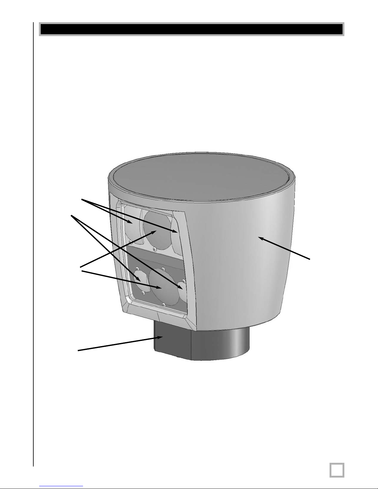
Laser
Emitters
(Groups of 16)
Laser
Receivers
(Groups of 32)
Motor
Housing
Figure 1. HDL-64E design overview.
The HDL-64E employs a direct drive motor system — there are no belts or chains in the
drive train.
Housing
(Entire unit spins
at 5-15 Hz)
.
www.velodyne.com
HDL-64E User’s Manual
2
Page 6
Installation Overview
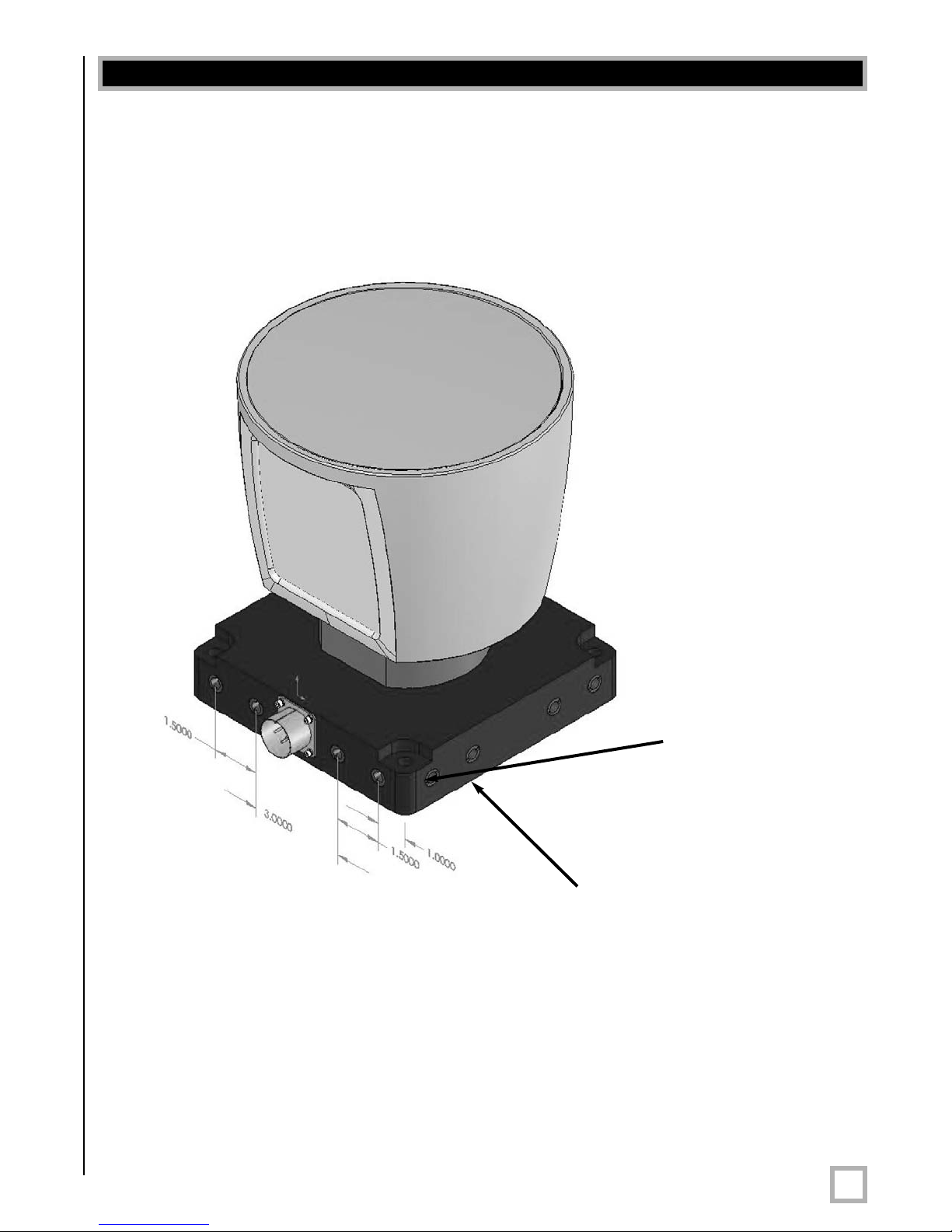
Front/Back Mounting
The HDL-64E base provides two mounting options: side mount and top mount. See Figure 2
for front/back mounting options, Figure 3 for side/side mounting, and Figure 4 for top
mounting instructions.
Four M8-1.25 x 12mm
deep mounting points.
(Four per side, for a
total of 16.)
Mounting
Base
. Front and back HDL mounting illustration.
e 2
Figur
See Figure 2. This figure shows the HDL-64E’s base plate screw locations with threaded inserts
for standard M8 hardware.
.
www.velodyne.com
HDL-64E User’s Manual
3
Page 7

Side Mounting
Mounting
Base
Figure 3. Side/side HDL mounting illustration.
.
www.velodyne.com
HDL-64E User’s Manual
4
Page 8

Top Mounting
Four .406” through
holes for top mount
option to secure the
HDL to the vehicle.
Figure 4. HDL top mounting illustration.
Figure 4 shows the location of four .406” thru holes for top mounting.
For all mounting options, be sur
shock without risk of detachment. The unit need not be shock proofed — it is designed to
withstand standar
The HDL-64E is weatherpr
The spinning nature of the HDL-64E helps the unit shed excess water from the front window
that could hamper performance. However, it is advisable to avoid exposing the HDL-64E to
extreme weather conditions such as driving rain.
.
www.velodyne.com
d automotive G-for
oofed to withstand wind, rain, and other adverse weather conditions.
e the HDL-64E is mounted secur
ces.
ely to withstand vibration and
HDL-64E User’s Manual
5
Page 9

Wiring
The HDL-64E comes with a pre-wired connector, wired with power, DB9 serial, and standard
R
J-45 Ethernet connectors.The connector wires are approximately 25’ in length.
Power. Connect the red and black wires to vehicle power. Be sure red is positive polarity. THE
HDL-64E IS RATED ONLY FOR 12 VOLTS. Any voltage applied over 16 volts could damage the
unit. Expect the unit to draw 4-6 amps during normal usage.
NOTE: The HDL-64E does not have a power switch. It spins whenever power is applied.
The HDL-64E has a lockout circuit that prevents its lasers from firing at low RPMs.
Ethernet. This standard Ethernet connector is designed to connect to a standard PC. See the
next section on usage for UDP packet formats.
Serial Interface. The connector also features an RS-232 DB9 serial connector. This connector
allows for a firmware update to be applied to the HDL-64E (Velodyne may release firmware
updates from time to time). It also accepts commands to change the RPM of the unit.
Cable Diagram. If you wish to wire your own connector, refer to Appendix B for a layout of the
wiring pins.
Usage
Output
The HDL-64E outputs UDP Ethernet packets. Each packet contains a data payload of 1206
bytes that consists of 12 blocks of 100-byte firing data followed by six bytes at the end of each
packet that contains a spin counter and firmware version information. Each packet can be for
either the upper or lower laser banks (called “laser blocks”) - each bank contains 32 lasers.
The packet format is as follows:
2 bytes of header info. This header indicates whether the packet is for the upper block
or the lower block. The upper block will have a header of 0xEEFF and the lower block
will have a header of 0xDDFF
2 bytes of rotational info. This is an integer between 0 and 35999. Divide this
number by 100 to get degr
32 laser returns broken into 3 bytes each. Each return contains two bytes of
distance information in .2 centimeter increments, and one byte of intensity information
(0 – 255, with 255 being the most intense return). A zero return indicates no return
up to 65 meters.
.
ees fr
om 0.
2 bytes spin count (binary). This field is incremented for each revolution. After
65,535 r
Note: The HDL-64E will ouput three upper block packets for every one lower block packet. This
provides more resolution when identifying objects at greater distances.
The minimum return distance for the HDL-64E is approximately three feet.
than this should be ignor
.
www.velodyne.com
evolutions, the counter r
ed.
esets to 0.
Returns closer
HDL-64E User’s Manual
6
Page 10

Correction Angles
Each HDL-64E laser is fixed with respect to vertical angle and offset to the rotational index data
p
rovided in each packet. For each data point issued by the HDL-64E, rotational and horizontal
correction factors must be applied to determine the point’s location in 3-D space referred to by
the return. Appendix A shows correction factors for both the upper and lower laser blocks.
Controlling the Spin Rate
The HDL-64E can spin at rates ranging from 300 RPM (5 Hz) to 900 RPM (15 Hz). The default
is 600 RPM (10 Hz). Note that changing the spin rate does not change the data rate – the
unit will send out the same number of packets (at a rate of one million data points per second).
The image resolution will increase or decrease depending on rotation speed. See Appendix C
for angular resolution figures for various spin rates.
To control the HDL's spin rate, connect the serial cable to an available RS-232 COM port and
issue a serial command of the format #HDLRPMnnn$ where nnn is an integer between 300
and 900. The characters are case sensitive and must be CAPS. The HDL64E will adopt the
new spin rate. Use the following serial parameters: Baud 9600, Parity: None, Data bits: 8,
Stop bits: 1. The HDL-64E has no echo back feature, so no serial data will be returned from
the HDL-64E.
F irm ware Update
Velodyne may issue firmware updates from time to time. To apply the update, connect the
DB9 RS-232 cable to a standard Windows-compatible PC’s serial port. The HDL-64E must
be powered up and spinning during the update.
Execute the file supplied by Velodyne – all the software and firmware is included to update the
unit. Once the file is executed, the following screen will appear:
Press update and the unit will update. If the update was successful, the unit will begin to spin
e running. If the first update
down for a few seconds then power back up with the new fir
is not successful, it is r
assistance fr
om Velodyne.
ecommended to try the update again several times before seeking
mwar
NOTE: The entire new firmware is uploaded and checksummed before being applied to the flash
memory inside the HDL-64E. If the checksum is corrupted, no software update occurs. This
protects the unit in the event of power or data loss during the firmware update.
.
www.velodyne.com
HDL-64E User’s Manual
7
Page 11

Troubleshooting
U
se this chart to troubleshoot common problems with the HDL-64E.
roblem Resolution
P
Unit doesn’t spin Verify power connection and polarity.
Verify proper voltage – should be 12 volts
drawing about 3-4 amps.
Remove bottom cover and check inline fuse.
Replace if necessary.
Unit spins but no data Verify Ethernet wiring.
Verify packet output from another source
(e.g. Etherreal/Wireshark).
No serial communication Verify RS-232 cable connection.
Unit must be active and spinning for
RS-232 update.
It may take several tries for the update
to be effective.
.
www.velodyne.com
HDL-64E User’s Manual
8
Page 12

Specifications
ensor:
S
Laser:
Mechanical:
Output:
• 64 lasers
• 360 degree horizontal field of view (azimuth)
0.09 degree angular resolution (azimuth)
•
• 26.8 degree vertical field of view (elevation)
• <5 cm resolution (distance)
5-15 Hz field of view update (user selectable)
•
• 50 meter range for pavement (~0.10 reflectivity)
• 120 meter range for cars and foliage (~0.80 reflectivity)
• >1m points per second
• < 0.05 miliseconds latency
• Class 1M - eye safe
• 4 x 16 lasers assemblies
• 905 nm wavelenth
• 5 nanosecond pulse
• Adaptive power system for minimizing saturations and blinding
• Beam Shape:
• 12-16V input @ 4 Amps (max)
• 10" tall cylinder of 8" OD radius
• 100 MBPS Ethernet with UDP
Lower Block @ 100 feet: 6” x .8” (w x h)
Upper Block @ 100 feet: 4” x .8” (w x h)
.
www.velodyne.com
HDL-64E User’s Manual
9
Page 13

Appendix A - Laser Correction Factors and Data
Packet Construction/Interpretation
Firing Order - Upper 32 Lasers Firing Order - Lower 32 Lasers
- Header 0xEEFF - Header 0xDDFF
Laser Laser
Number RCF* VCF** HCF*** Number RCF* VCF**
1 -4.9542347365 -7.1581190889 4.00 1 -7.443011494 -22.73788631
2 -2.8147367929 -6.8178216657 -4.00 2 -4.224232979 -22.22607199
3 2.8147367929 0.3178216657 4.00 3 4.224232979 -11.51392801
4 4.9542347365 0.6581190889 -4.00 4 7.443011494 -11.00211369
5 -0.6935618777 -6.4776502171 4.00 5 -1.033172642 -21.71468598
6 1.4410693300 -6.1375926248 -4.00 6 2.169097681 -21.20368655
7 -1.4698693300 -8.5208123798 4.00 7 -2.197897681 -24.79027242
8 0.6647618777 -8.1798890134 -4.00 8 1.004372642 -24.27632105
9 3.5633243031 -5.7976368074 4.00 9 5.36381546 -20.69303226
10 5.7049959563 -5.4577707152 -4.00 10 8.590013444 -20.18268193
11 2.7859367929 -7.8391405361 4.00 11 4.195432979 -23.76296827
12 4.9254347365 -7.4985546449 -4.00 12 7.414211494 -23.25017094
13 -4.9974347365 -3.0802132582 4.00 13 -7.486211494 -16.61531942
14 -2.8579367929 -2.7406338106 -4.00 14 -4.267432979 -16.10593813
15 -5.7769959563 -5.1179823277 4.00 15 -8.662013444 -19.6725946
16 -3.6353243031 -4.7782596485 -4.00 16 -5.43581546 -19.16272948
17 -0.7367618777 -2.4010364689 4.00 17 -1.076372642 -15.59649644
18 1.3978693300 -2.0614092976 -4.00 18 2.125897681 -15.08695403
19
20 0.6215618777 -4.0989635311 -4.00 20 0.961172642 -18.14350356
21 3.5201243031 -1.7217403515 4.00 21 5.32061546 -14.57727052
22
23 2.7427367929 -3.7593661894 4.00 23 4.152232979 -17.63406187
24 4.8822347365 -3.4197867418 -4.00 24 7.371011494 -17.12468058
25 -5.0406347365 0.9985546449 4.00 25 -7.529411494 -10.48982906
26 -2.9011367929 1.3391405361 -4.00 26 -4.310632979 -9.977031727
27 -5.8201959563 -1.0422292848 4.00 27 -8.705213444 -13.55731807
28 -3.6785243031 -0.7023631926 -4.00 28 -5.47901546 -13.04696774
29 -0.7799618777 1.6798890134 4.00 29 -1.119572642 -9.463678954
30
31 -1.5562693300 -0.3624073752 4.00 31 -2.284297681 -12.53631345
32
-1.5130693300 -4.4385907024 4.00 19 -2.241097681 -18.65304597
5.6617959563
1.3546693300
0.5783618777
-1.3820176723 -4.00 22 8.546813444 -14.067405
2.0208123798
-0.0223497829 -4.00 32 0.917972642 -12.02531402
-4.00
30
2.082697681 -8.949727577
* RCF: Rotational Cor
rection Factor in Degrees **VCF: Vertical Correction Factor in Degrees
***HCF: Horizontal correction factor in cm. This refers to the physical horizontal (i.e. left or right)
offset of each of the laser blocks. The same value applies to both upper and lower blocks.
ection factor for odd number
Horizontal cor
r
Horizontal correction factor for even numbered lasers: (-)4cm.
.
www.velodyne.com
ed lasers: (+)4cm.
HDL-64E User’s Manual
10
Page 14

Packet construction:
DP, 100 bytes of data per firing, 12 blocks of data per packet, plus six status bytes at the end of
U
each packet described below. There are three upper blocks returned for each lower block returned.
Data layout:
• Two bytes header info, two bytes rotational info (0-35999, divide by 100 to get degrees)
• 32 laser returns broken into three bytes each:
- Two bytes distance information (in .2 CM increments)
- One byte intensity information (0-255 with 255 being the most intense reflection)
• Six status bytes that alternate between packets. The end of the packet will show either:
- A reading showing the internal temperature of the unit. You will see a " DegC" ASCII string as the
last four bytes of the packet. The two bytes before this string are the thermistor's reading in C
in hex 8.8 format. This is in " big indian format" - i.e. the byte immediately preceding the DegC
text is the whole degrees, and the byte preceding that is the fraction of a degree in 1/256
increments. So if you see c0 1a, the temperature of the thermistor is 26.75 degrees C.
- Or, the version number of the firmware in ASCII character format " Vn.n" where n.n is the version
number, i.e. "1.5".
.
www.velodyne.com
HDL-64E User’s Manual
11
Page 15

Appendix B - Connector Wiring Diagram
J1
J2
D
E
I
J
F
G
H
A
B
C
KEY
PIN 1
SERIAL CONNECTOR
ETHERNET CONNECTOR
P1
P1
3
J2
8
7
5
462
1
J1
EHTERNET OUT (+)
EHTERNET IN
(+)
EHTERNET OUT (-
)
EHTERNET IN
(-
)
GND
12-16VDC (+)
P5
P3
N/C
N/C
N/C
N/C
N/C
N/C
N/C
N/C
N/C
N/C
RED
BLK
YEL
SHIELD
RED
B
C
F
G
I
J
D
A
H
CENTER CON.
E
User Interface Harness
.
www.velodyne.com
HDL-64E User’s Manual
12
Page 16

Appendix C - Angular Resolution
Lower Block
RPM RPS Points Per Points Per Revolution Angular Resolution
Revolution Per Laser (degrees)
300 5 50000 1562.5 0.2304
600 10 25000 781.25 0.4608
900 15 16667 521 0.6912
Upper Block
RPM RPS Points Per Points Per Revolution Angular Resolution Post-Lower-Block
Revolution Per Laser (degrees) Angular Resolution
(degrees)**
300 5 200000 6250 0.0576 0.1152
600 10 100000 3125 0.1152 0.2304
900 15 66667 2083 0.1728 0.3456
Notes:
The HDL-64E generates 1 million points per second
• The lower block reports 250,000 points
• The upper block reports 750,000 points
There are three upper block packets then one lower block packet reported, then the pattern repeats.
** The first upper block measurement after the lower block measurement reports has half the
angular resolution.
.
www.velodyne.com
HDL-64E User’s Manual
13
Page 17

T
63-HDL-64E Rev B JUN07
.
www.velodyne.com
Velodyne Acoustics, Inc.
345 Digital Drive
gan Hill, CA 95037
Mor
408.465.2800 voice
408.779.9227 fax
408.779.9208 service fax
www.velodyne.com
Service E
Product E
echnical E
Sales E
-mail: service@velodyne.com
-mail: help@velodyne.com
-mail: techhelp@velodyne.com
-mail: lidar@velodyne.com
HDL-64E User’s Manual
14
 Loading...