

Page 1
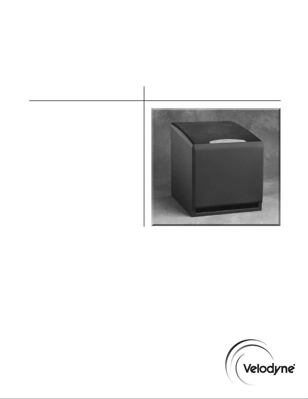
DPS Series
DPS-10
DPS-12
USER’S
MANUAL
Audio/Video Subwoofer System
Page 2
Caution
IMPORTANT
A
Caution
To
reduce
the
risk
of
electric
servicing
The
"dangerous
of
The
maintenance
1.
2.
3.
4.
5.
6.
7.
8.
9.
10.
11.
12.
13.
14.
15.
16.
17.
18.
19.
to
qualified
lightning
voltage"
electric
shock
exclamation
Read
InsncUo
IIeIIIn
Instructions
H....
Worning_
adhered
Follow
Insnclions
Wlter
and
washbowl,
CaJts
and
the
manufacturer.
Wan
Dr
Ceiling
by
the
manufacturer.
Ventilation
proper
ventilation.
that
may
that
may
H
••
t -
stoves,
or
Power
Sources
the
operating
aroundl
..
(a
plug
having
This
is a safety
If
the
plug
the
safety
Power-Conl
on
or
pinched
convenience
CI
..
ning
Non
...
P.riods
for a long
ObJect
and
onto
the
oa.g.
a.
The
power-supply
b.
Objects
c.
The
product
d.
The
product
e.
The
product
S.rvicing
operating
Lightning
and
unused
Overl
....
can
result
CAUTION:
service
flash
with
arrowhead
wnhin
to
persons.
point
symbol
(servicing)
to.
..
-
-
Moisture
kitchen
sink,
Stands
instructions
All
-
All
-
-
-
Mounting
-
The
product
For
example,
block
the
ventilation
impede
the
flow
The
product
other
products
-
The
instructions
Dr
Polarization
one
blade
feature.
should
still
purpose
of
the
Protection
by
items
receptacles,
-
The
product
-
The
period
of
time.
Liquid
Enby
enclosure.
Requl~ng
instructions.
-
ing
To
have
has
does
has
-
The
For
for
long
-
Do
in a risk
prevent
S
....
fallen
been
been
user
added
not
of
cord
not
periods
fire
electrical
personnel.
the
safety
The
All
laundry
The
should
product
If
fail
-
power
-
c.
or
should
All
protection
overload
SAFETY
shock,
do
not
symbol
product's
is
intended
in
the
and
operating
safety
and
wamings
operating
The
product
tub,
product
-
The
product
should
be
the
product
openings;
of
air
through
be
situated
that
produce
should
or
as
marked
-
This
product
wider
than
you
are
unable
to
fi~
contact
polarized
placed
and
should
liquid
exposed
appear
dropped
other
or
plug.
Power-supply
upon
the
point
be
cord
of
Care
should
-
The
product
or
plug
has
has
to
to
or
not
servicing
for
of
time,
wall
electric
shock,
remove
is
enclosure
to
alert
literature
operating
on
the
and
use
should
in
a
wet
should
should
situated
or
placed
the
away
heal
be
on
may
the
other).
to
your
cords
or
against
at
which
cleaned
the
product
be
been
been
spilled
rain.
operate
damaged.
attempt
should
the
product
unplug
outlets,
shock.
match
cover
intended
should
connected
the
should
normally
to
that
may
the
user
accompanying
instructions
instructions
product
instructions
not
be
used
basement,
be
used
be
mounted
so
that
not
in
a
ventilation
from
product.
be
equipped
This
insert
the
electrician
should
them,
they
exn
only
as
recommended
should
taken
so
that
be
damaged.
into
the
or
to
service
be
referred
during a lightning
it
from
the
extension
wide
blade
INSTRUCTIONS
Atl
(or
back).
No
user-serviceable
alert
the
user
be
of
sufficient
to
the
presence
the
subwoofer.
should
be
read
should
be
and
in
the
operating
should
be
followed.
near
water -for
near a swimming
only
with a cart
to a wall
its
location
or
position
be
situated
on a bed,
built~n
installation
openings.
heat
sources
such
to a power
plug
plug
to
be
paying
be
serviced
exhibits a marked
the
wall
cords
supply
with a polarized
will
fit
into
fully
into
replace
your
routed
so
that
particular
from
the
product.
by
unplugged
objects
do
by
qualified
product.
product
to
qualified
storm
outlet.
or
integral
of
plug
to
to
the
magnitude
of
before
retained
pool
or
or
ceiling
sofa,
such
as
only
the
power
the
outlet,
obsolete
they
attention
the
manufacturer.
from
not
fall
service
change
beyond
service
or
convenience
wide
slot,
parts
presence
important
the
instructions
example,
stand
does
as a bookcase
radiators,
of
altemating-<:urrent
are
the
and
what
when n is
of
to
constitute a risk
product
for
future
near a bathtub,
or
the
like.
recommended
only
as
not
interfere
rug,
or
similar
heat
the
type
outlet
only
try
reversing
outlet.
not
likely
to
cords
outlet
when
liquids
are
personnel
in
performance.
is
described
personnel.
left
receptacles
fully
inserted.
inside.
Refer
uninsulated
operating
recommended
Do
is
operated.
reference.
should
with
surface
or
cabinet
registers,
described
line
plug
one
way.
the
plug.
not
defeat
to
be
walked
at
plugs,
lefl
unused
not
spilled
when:
in
unattended
as
and
be
by
its
in
the
this
.
www.velodyne.com
DPS User’s Manual
i
o
Page 3

Table of Contents
Congratulations . . . . . . . . . . . . . . . . . . . . . . . . . . . . . . . . . . . . . . . . . . . . . . . . . . . .1
Installation . . . . . . . . . . . . . . . . . . . . . . . . . . . . . . . . . . . . . . . . . . . . . . . . . . . . . . .2
Rear Panel Connections . . . . . . . . . . . . . . . . . . . . . . . . . . . . . . . . . . . . . . . . . . . . . .6
Rear Panel Connections - Detailed Explanation . . . . . . . . . . . . . . . . . . . . . . . . . . . . . . .7
Placement . . . . . . . . . . . . . . . . . . . . . . . . . . . . . . . . . . . . . . . . . . . . . . . . . . . . . . .9
Care of Your Subwoofer . . . . . . . . . . . . . . . . . . . . . . . . . . . . . . . . . . . . . . . . . . . . . .9
Troubleshooting and Service . . . . . . . . . . . . . . . . . . . . . . . . . . . . . . . . . . . . . . . . . .10
Specifications . . . . . . . . . . . . . . . . . . . . . . . . . . . . . . . . . . . . . . . . . . . . . . . . . . . .11
Velodyne Products . . . . . . . . . . . . . . . . . . . . . . . . . . . . . . . . . . . . . . . . . . . . . . . . .12
.
www.velodyne.com
DPS User’s Manual
ii
Page 4

Congratulations
Congratulations on your purchase of a Velodyne Digital Power Slot™ (DPS) subwoofer system.
This system represents the state-of-the-art in low frequency reproduction. Read and follow the
instructions below to insure safe and proper system operation.
Warning!
To prevent fire or shock hazard, do not expose this equipment to rain or moisture. To avoid
electrical shock, do not open speaker enclosure or amp chassis cover
warnings on the equipment itself. There are no user serviceable parts inside. Please refer all
service questions to your authorized Velodyne dealer.
Prior to Installation
Please unpack the system carefully. Please save the carton and all packaging materials
for future use. Record the serial number in the space provided on the warranty card for
future reference.
Product Features and Controls
• Microprocessor-controlled
• Four selectable presets for customized listening mode
• Selectable option to activate Auto-on/off feature
• Night-mode setting
• Built-in 185 watt (RMS) power amplifier (DPS-10)
• Built-in 200 watt (RMS) power amplifier (DPS-12)
• Adjustable (40 to 120 Hz) low-pass crossover with Subwoofer Direct setting
• Speaker-level inputs and outputs
• Line-level inputs
• Variable volume control
• Selectable phase control (0 or 180 degrees)
• Dual staggered low-pass crossover; 12 dB/octave initial, 24 dB/octave ultimate
• Anti-clipping circuit
• Over excursion protection
• Slot loaded design
. Please observe all
.
www.velodyne.com
DPS User’s Manual
1
Page 5
Installation
Your new subwoofer system provides for a number of installation options. Read all the
installation information below in order to determine which installation option is best for your
system. Remember to perform all installation procedures with system power turned off.
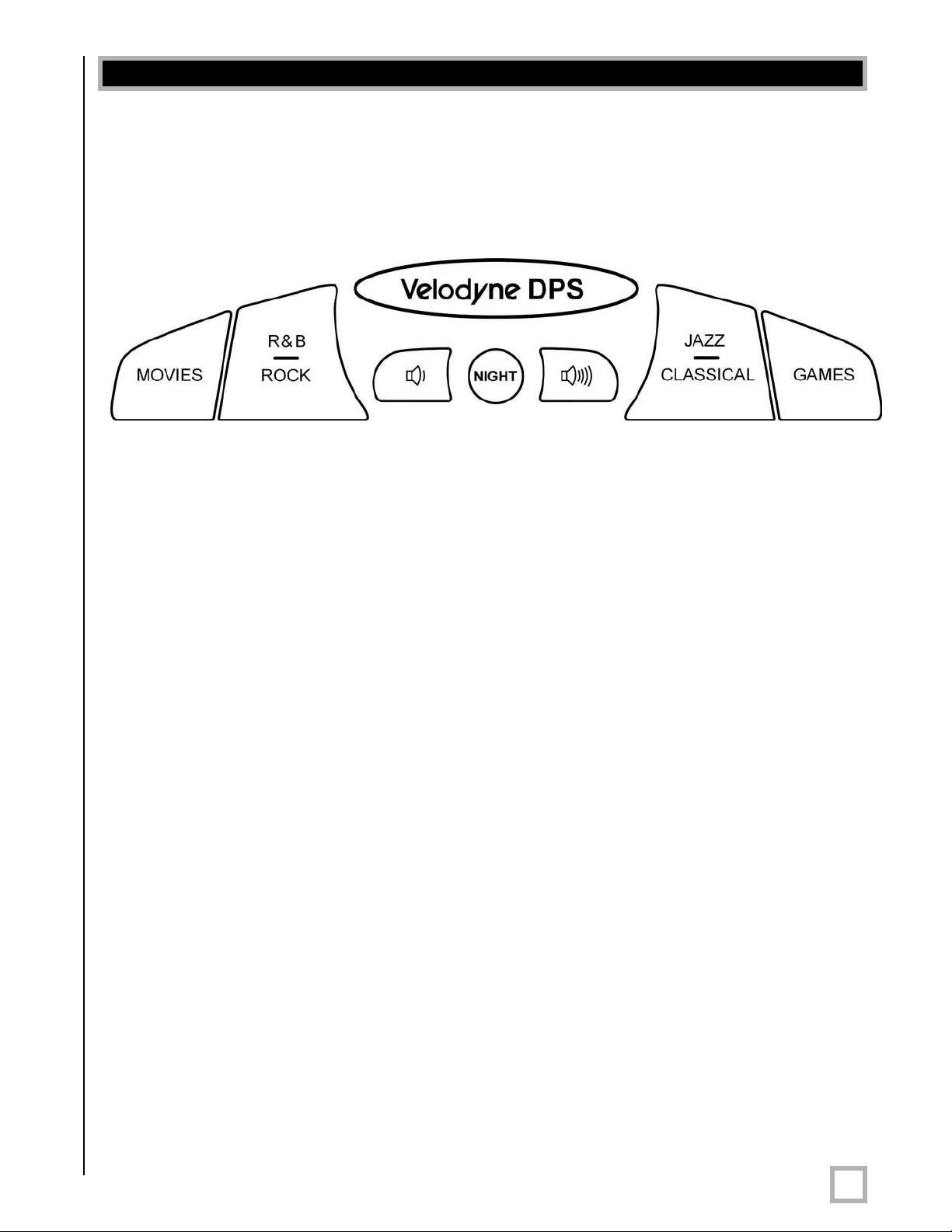
Figure 1. Front Panel Display
Front Panel Display
Figure 1 shows the front panel display, which is located on the top of your subwoofer.
Presets
There are four presets, consisting of Movies, R&B — Rock, Jazz — Classical, and Games.
Whichever preset you choose is illuminated with a blue LED. The presets provide the following
characteristics for bass reproduction:
Movies:
R&B — Rock: Provides the driving bass found in today’s rock music.
Jazz — Classical: The tightest, cleanest, lowest distortion bass.
Games: Maximum loudness available for the impact of video games.
Each preset has its own characteristic with respect to subsonic filter, volume differential, and
a single equalizer (EQ) in order to optimize the listening mode for the preset.
Maximum output and impact for explosions and
other action adventure movie content.
.
www.velodyne.com
DPS User’s Manual
2
Page 6

The following table indicates musical style and which preset is recommended for it.
Musical Style Suggested Preset
Action Adventure Movies Movies
Alternative Rock Jazz — Classical
Blues Jazz — Classical
Broadway and Vocalists Jazz — Classical
Children’s Music Jazz — Classical
Christian and Gospel Jazz — Classical
Classic Rock R&B — Rock
Classical Jazz — Classical
Country — Rock R&B — Rock
Country — Soft Jazz — Classical
Dance and DJ R&B — Rock
Folk Jazz — Classical
Hard Rock and Metal R&B — Rock
Indie Music R&B — Rock
Latin Music R&B — Rock
Miscellaneous Jazz — Classical
Movies — Non-Action Adventure Jazz — Classical
New Age Jazz — Classical
Opera and Vocal Jazz — Classical
Pop R&B — Rock
R&B R&B — Rock
Rap and Hip-Hop R&B — Rock
Rock R&B — Rock
Soundtracks R&B — Rock or Jazz —
Classical
Video Games Games
.
www.velodyne.com
DPS User’s Manual
3
Page 7
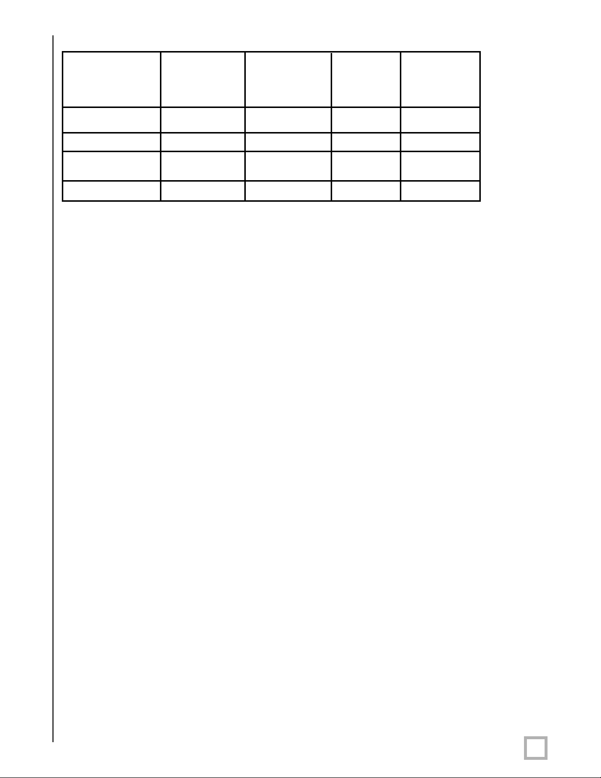
The following table shows the settings for various presets:
Subsonic
Filter EQ
Preset Frequency Frequency Level Differential
Movies 24 Hz 37 Hz +4 dB +8 dB
EQ Volume
R&B – Rock
Jazz – Classical 24 Hz N/A N/A N/A
(Reference)
Games 34 Hz 62 +4 dB +4 dB
RESTORE DEFAULTS – This feature allows you to restore default settings for your DPS
subwoofer
the unit’s power light will blink three times indicating that you have restored defaults.
When you press the presets in the above order, the power light will blink three times indicating
that you have restored defaults. The default preset is Jazz-Classical, and the unit’s volume is
reset to level 35 (out of 100).
. By pressing the presets in EXACTLY the following order on the front panel display,
1. Movies
2. R&B – Rock
3. Jazz – Classical
4. Games
5. Games
6. Jazz – Classical
7. R&B – Rock
8. Movies
27 Hz 52 Hz +3 dB +5 dB
Night Mode
Night mode limits the maximum output of the subwoofer for late night listening or to be more
considerate of close neighbors. Press the NIGHT button to turn the night mode feature on or
off. Engaging the night mode causes the LED lights to burn less brightly. Night mode does not
universally diminish the volume, rather, on louder passages, the maximum output of the unit is
limited. It may be that you will hear little or no difference in the output of the woofer when night
mode is activated. However, when an explosion or other loud transient is played, you should
notice less ouput.
VOLUME Control
This control allows you to balance the output from the subwoofer to the main speakers in your
system. This control should be set to achieve similar volume level from between both the main
speakers and subwoofer. When pressing volume up or down, the speed at which the power light
blinks indicates subwoofer volume - the faster the blinking, the louder the unit plays. After the
volume is changed (up or down), there will also be two sets of center LED blinks. Slower blinks
represent tens and faster blinks represent ones. If the LED blinks thr
six times, this means that the volume is set at 36. The volume range is from 1 to 99.
.
www.velodyne.com
ee times, pauses, then blinks
DPS User’s Manual
4
Page 8

IMPORTANT NOTE: Some manufacturers preset their receivers with the Sub-Out channel
signal at a minimum level. It is very important to verify that your receiver Sub-Out channel is set
to the same output level, or higher, as your front right and left channels. Refer to your receiver
manual for the individual channel level adjustment procedure.
WARNING: If your receiver Sub-Out channel is set too low, the subwoofer may appear
to have a weak output, it may sound noisy or distor
may not work properly.
Auto-On/Off Feature
The auto-on/off feature allows the subwoofer to turn itself off when not in use. On the top front
panel display; press both the left button (Movies) and right button (Games).
NOTE: When pressing both the Movies and the Games buttons, the timing is critical - both
buttons must be depressed at exactly the same time for the feature to work.
ted, and the Auto-On/Off feature
- If the center LED blinks for approximately five seconds, the auto-on/of
If activated, the subwoofer will monitor its input, and if there is no signal present for
approximately 15 minutes, it will shut down and go into standby mode. As soon as a signal
is present again, the subwoofer will immediately turn itself back on.
- If the center LED blinks for approximately two seconds, the auto-on/off feature is
bypassed. The subwoofer will remain on until the power switch is turned off.
WARNING: If the Sub-Out channel signal level from your receiver is too weak, this feature will
not operate properly
Light Control Function
If you wish, you can deactivate the blue front panel lights on your DPS unit. To do this, press
both the volume up and volume down buttons simultaneously — the power and preset lights
should turn off. To reactivate the lights, press both volume buttons again.
. See VOLUME CONTROL section.
f feature is activated.
.
www.velodyne.com
DPS User’s Manual
5
Page 9

Figure 2. DPS Rear Panel Connections
R ear Panel Connections
Figure 2 shows the connections on the rear panel of the DPS. Following are brief descriptions
of the connections described in Figure 2. More detail on these connections can be found on
the next page.
(1) LOW-PASS CROSSOVER
Use this knob to select the high-frequency range at which you wish to cut off the signal to
the subwoofer
is invoked and the subwoofer plays all frequencies up to 200 Hz.
(2) PHASE Switch
Allows you to optimize the subwoofer performance for the location and your listening position.
Select the switch position at which you hear more bass.
(A) LINE INPUT/LFE Input
Connect these jacks to the LINE OUT preamp output, LFE output or subwoofer output jack(s)
of your receiver/processor
single cable into the “L” — LFE input.
. When the knob is turned all the way to the left, the Subwoofer Direct feature
. If using the LFE output from your receiver or processor, plug the
.
www.velodyne.com
DPS User’s Manual
6
Page 10

(B) SPEAKER LEVEL INPUT Terminals
Connect these input terminals to the speaker output terminals of your amplifier or receiver.
If you use this method of connection, when you go to the receiver speaker set up menu, make
sure you select the large speaker option.
Note: Do not use both the LINE INPUT/LFE INPUT connections and SPEAKER LEVEL INPUT
connections simultaneously
(C) SPEAKER LEVEL OUTPUT Terminals
Sends a speaker-level signal to the front speakers.
Caution!!!
To avoid damage to your main amplifier, be sure to maintain correct polarity when making all
connections. Red (positive) to red, and black (negative) to black. Be sure that all connections
are tight, and that there are no loose strands or frayed wir
Power Switch
The master power switch is located on the lower right half of the unit. This rocker style switch is
the main on/off for the unit. This switch should be set to position 1 for on (up), 0 for off (down).
.
es.
R ear Panel Connections - Detailed Explanation
Your new subwoofer is equipped with both speaker-level and line-level inputs. Use the
RCA/Phono type “INPUT” jacks when connecting your subwoofer to a pre-amp, signal
processor, or line-level crossover. The “SPEAKER LEVEL INPUT” jacks connect directly to the
speaker outputs of an integrated amplifier or receiver. Your amplifier section will notice no
additional loading effects when you use these inputs because of their high impedance.
Low-Pass Crossover
Both sets of inputs sum the left and right channels together and the resulting signal is passed
through an adjustable low-pass crossover before being amplified. The crossover control allows
you to adjust the upper limit of the subwoofer’s frequency response from 40 to 120 Hz.
The subwoofer’s response will begin rolling off above the frequency you set this control to.
You should set the crossover frequency to obtain a smooth and seamless transition from
the subwoofer to the main speakers in your system. If your main speakers are smaller
units with limited low frequency output, you may wish to choose a higher frequency (such as
100 -120 Hz) than you would with larger speakers which have greater low frequency output.
With larger speakers, you might start with this control set lower, such as 80 Hz.
Subwoofer Direct
Subwoofer Direct is a setting on the low-pass crossover knob and will allow frequencies up to
200 Hz into the subwoofer. If you are not using an external crossover, we recommend that you
use the one provided within the DPS unit for optimum performance.
Phase Adjustment - 0°/180°
This control allows you to “reverse” the phase of the subwoofer’s output signal 180° to correct
for any possible mismatch and resulting cancellation between the subwoofer and your main
speakers. To adjust, simply listen to the system with music playing. Then move the switch from
one position to the other and listen for a change in low frequency output. The correct position
will have a greater amount of apparent low frequency output.
.
www.velodyne.com
DPS User’s Manual
7
Page 11

Speaker Level Output
When connected in this fashion, your satellite speakers will be fed the same input signal as the
subwoofer. This removes the lower bass from your satellites, enabling them to do a better job
reproducing high frequencies and giving your receiver’s amp more headroom (up to 50% more
power). You may also connect your satellites directly to your receiver or amplifier along with the
subwoofer if you wish to bypass this crossover.
Caution!!!
To avoid damage to your main amplifier, be sure to maintain correct polarity when making all
connections. Red (positive) to red, and black (negative) to black. Be sure that all connections
are tight, and that there are no loose strands or frayed wir
es.
A Word About Your Receiver’s Crossover and
the DPS Crossover
Your Velodyne DPS subwoofer is designed to operate using the full range audio signal for input
when using the built-in crossover (controlled by the dial on the back panel). Many home theater
processors/receivers (Dolby Digital
this same function and are designed to be used with a powered subwoofer. In these
installations, you may want to bypass the crossover in either the processor or the Velodyne
subwoofer. In some cases, you may want to use BOTH crossovers. To do this, you can use both
your processor’s crossover and the one internal to the Velodyne sub. You should stagger the
frequencies (i.e., 120 Hz subwoofer, 80 Hz processor) for best results. To bypass the
subwoofer’s internal crossover when the unit is being fed a low pass signal from another
crossover, simply locate the knob marked “LOW-PASS CROSSOVER” on the rear panel of the
subwoofer and turn it counterclockwise to the “DIRECT” position. This will eliminate the internal
crossover from the signal path.
®
, DTS®, THX®) have a “subwoofer out” jack that performs
Note: If not using an external crossover, you should use the built-in crossover for optimal
performance. When using a single RCA sub out from the processor, it does not matter which
line level input (L/R) is used.
Interconnect Cables
When installing your new Velodyne subwoofer using the line-level connections, you should always
use shielded phono cables. There are many decent cables available today, most any of which
will work perfectly well. We do recommend that you keep the length of cable as short as
possible to avoid any potential noise problems. When using speaker level connections, use a
decent quality speaker cable that mates well with the connectors (at least 14 gauge). Be very
careful to avoid any loose or frayed strands that could result in a short, causing a dangerous
condition and possible damage to your unit. Cables of extremely large size are typically not
required. Extremely large gauge wire may not properly fit in the binding posts, resulting in a
poor connection and possible short circuits.
.
www.velodyne.com
DPS User’s Manual
8
Page 12

Placement
True subwoofers operate at extremely low frequencies, which are primarily omni-directional.
While it is recommended that the subwoofers be placed on the same plane as the satellite
speakers, room and system conditions often dictate otherwise. Keep in mind that frequency
response and output level can be drastically influenced by placement, depending on the acoustic
properties of your listening room. Typically, the optimum location for a subwoofer is in a front
corner of your listening room. This location will usually offer the greatest output levels and
optimum low frequency extension. The worst location for a subwoofer is typically far away from
any walls, close to the center of your room and near an opening or door way. Avoid these
locations when possible. When using a pair of Velodyne subwoofers in stereo, it is preferable
to place each subwoofer near the satellite of the same channel. Typically, a minimum
distance of one to two feet from your TV to the subwoofer will be adequate to avoid any
magnetic interference.
Caution!
This subwoofer has electronics built into the cabinet. Do not place the cabinet next to sources
of heat such as furnace registers, radiators, etc. Do not place the unit near sources of
excessive moisture, such as evaporative coolers, humidifiers, etc. The power cord should be
routed in such a way that it will not be walked on, pinched, or compressed in any way that could
result in damaging the insulation or wire.
Care of Your Subwoofer
Do not use any harsh detergents or chemicals to clean the cabinet. Abrasives, detergents, or
cleaning solutions will damage the finish on the cabinet. We recommend using a damp cloth to
clean the front, back and sides. Use a soft cloth with a good quality furniture polish to clean the
hand-rubbed, black lacquer
on continuously without any problems. If you plan to leave the unit unused for an extended period
of time, we recommend that you turn off the unit by the master power switch on the rear panel.
, painted top. During normal conditions, the subwoofer may be left
.
www.velodyne.com
DPS User’s Manual
9
Page 13

Troubleshooting and Service
Before seeking service for your amplifier or subwoofer, please re-check all systems. Following
is a simple troubleshooting guide to assist you.
1. Verify that the unit is plugged in and power outlet used is active.
2. Is the power switch on?
3. Is the unit receiving an input signal from your source?
4. Have all controls (volume, crossover, phase, etc.) been properly set?
5. If the unit has been running at high levels, one of the protection circuits may be engaged.
Has the amplifier overheated?
6. Make sure binding posts are tightened.
If the protection circuitry is active, the unit may cycle on and off until operating parameters
return to normal. Under more serious conditions, the unit may shut off completely. Normal
operation should return upon cooling, but you may be required to turn the power off and then
on again to reset the unit.
The following conditions require service by a qualified technician:
1. The power cord has become damaged
2. The unit does not appear to operate normally or exhibits a marked
change in performance
3. The unit has been exposed to water
4. Some part of the chassis or circuitry is physically damaged
Thank You for Purchasing a Velodyne!
.
www.velodyne.com
DPS User’s Manual
10
Page 14
Specifications
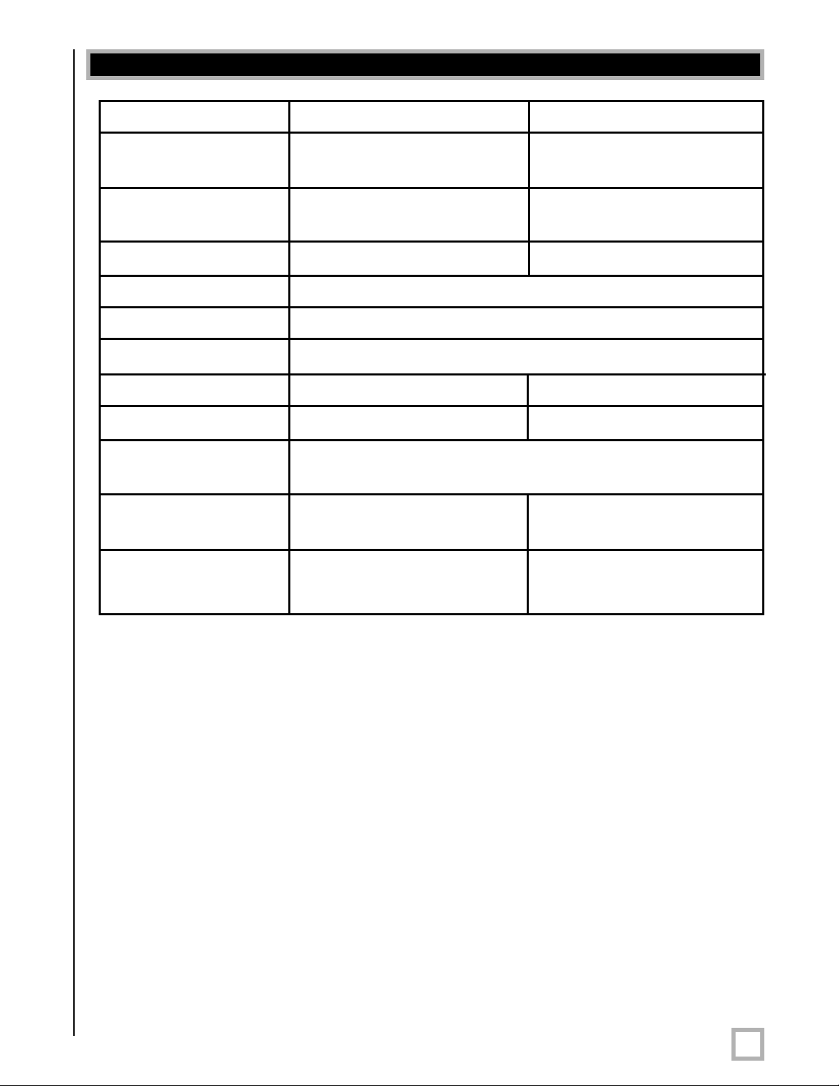
Specifications DPS-10 DPS-12
Driver 10” forward firing 12” forward firing
(8.2” piston diameter) (9.9” piston diameter)
Amplifier (Class A/B) 375 watts Dynamic/ 400 watts Dynamic/
185 watts RMS Power 200 watts RMS power
Frequency Response 28 Hz — 120 Hz (+/-3 dB) 25 Hz — 120 Hz (+/-3 dB)
Low-Pass Crossover 40 Hz — 120 Hz (12 dB/octave, 24 dB ultimate)
Inputs Line-level and speaker-level
Outputs Speaker-level
Magnet 40 oz. (2.5 lbs) 55 oz. (3.5 lbs)
Voice Coil 2” four-layer copper 2” four-layer copper
Warranty Three years (electronics - parts and labor),
Five years (drivers - parts and labor)
Cabinet (H/W/D) 16.25” x 14.5” x 17” 18.25” x 14.5”x 19”
(cm) 41.3 x 36.8 x 43.2 46.4 x 36.8 x 48.3
Shipping Weight
(approx.) 51 lbs. (23.2 Kg) 58 lbs. (26.4 Kg)
Specifications are subject to change without notice.
.
www.velodyne.com
DPS User’s Manual
11
Page 15
Velodyne Products
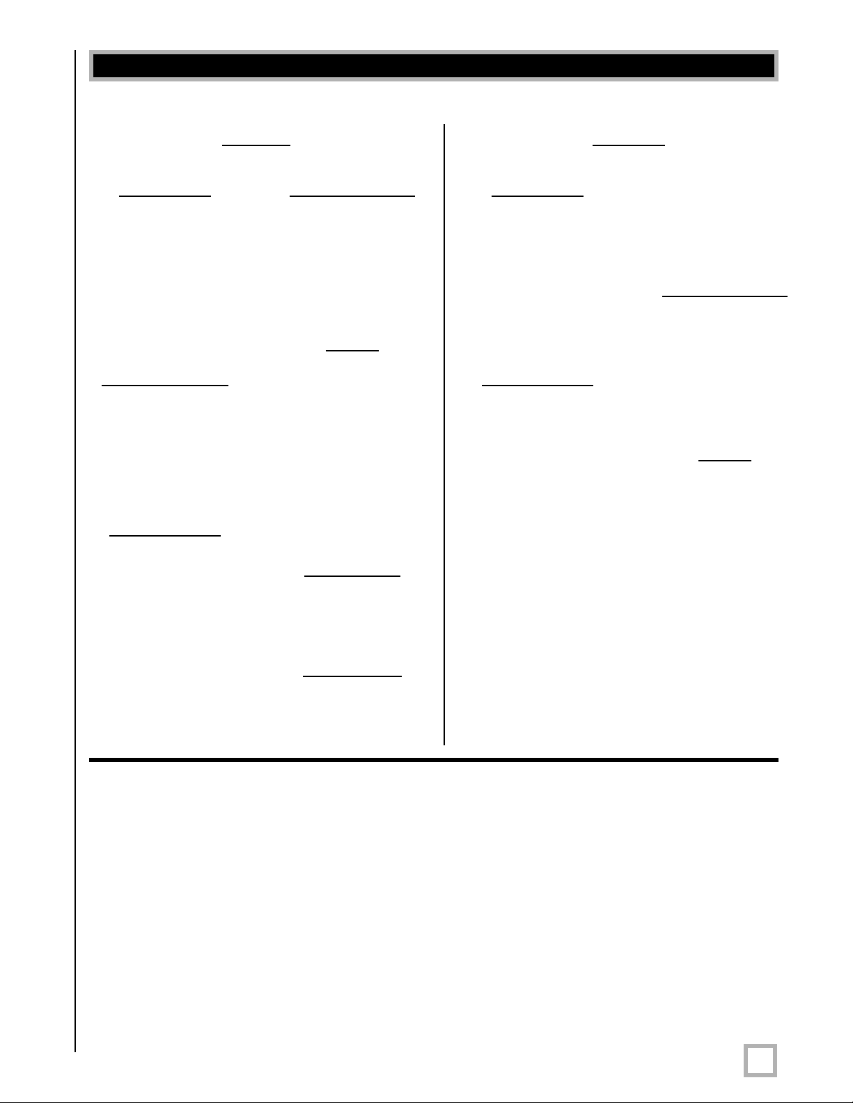
120V
® ®
DD Series
DD-10
DD-12
DD-15
DD-18
Digital Drive 1812
Signatur
DLS™-R Series
DLS-3500R
DLS-3750R
DLS-4000R
DLS-5000R
DPS™ Series
e Edition
SPL™-R Series
SPL-800R
SPL-1000R
SPL-1200R
SPL-1500R
SubContrator™
Series
SC-1250
SC-8
SC-10
SC-12
SC-15
SC-IW
SC-IF/IC
230V
DD Series
DD-10
DD-12
DD-15
DD-18
Digital Drive 1812
Signatur
CHT
e Edition
-R Series
CHT-8R
CHT-10R
CHT-12R
CHT-15R
SMS™ -1
SPL-800i
SPL™-R Series
SPL-800R
SPL-1000R
SPL-1200R
SPL-1500R
SubContrator™
Series
SC-1250
SC-8
SC-10
DPS-10
DPS-12
MicroVee™
MiniVee
MiniVee 10
SMS™-1
®
®
VRP Series
VRP-1000
VRP-1200
VX™ Series
VX-10
SC-12
SC-15
SC-IW
SC-IF/IC
.
www.velodyne.com
DPS User’s Manual
12
Page 16
FOR YOUR RECORDS. . .
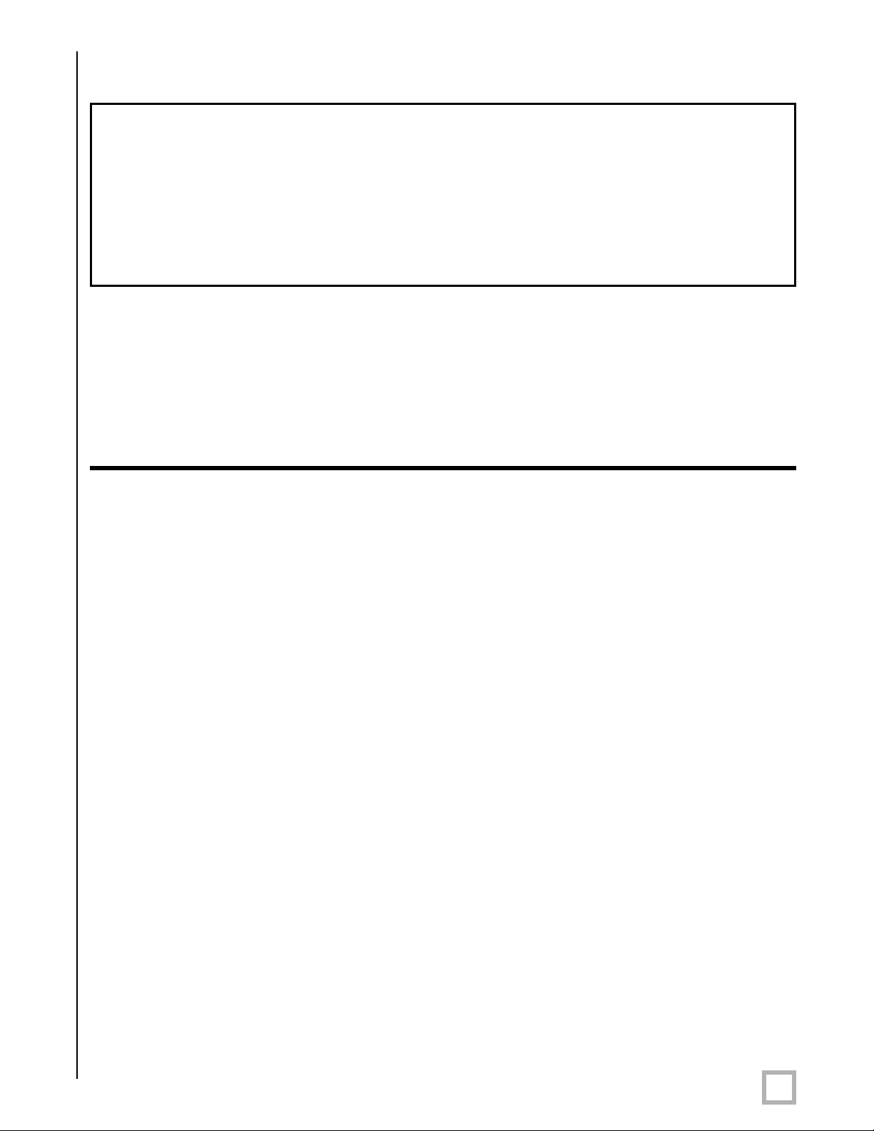
Date Puchased_________________________________________________________________
Dealer_________________________________________________________________________
Serial #________________________________________________________________________
*NOTE: Please complete and return your warranty card within ten (10) days or
Register. . . ON LINE . . . It’s faster . . . and easier
www.velodyne.com
LIMITED WARRANTY
VELODYNE ACOUSTICS, Inc. (“VELODYNE”) warrants all electronics for a period of three years, drivers for a period
of five years, and full range speakers for a period of five years. All VELODYNE products have a warranty from the
date of purchase against defects in materials and workmanship subject to the following conditions:
1.
VELODYNE is not responsible for defects which result from the use of an amplifier or controller other than
the one originally supplied with the unit (subwoofer) or defects which result from modifications or repairs
made by any component of the system by anyone other than a VELODYNE factory authorized
service representative.
2. This warranty is void if any repairs or service covered by the terms of this warranty are made to any
component of the system by anyone other than a VELODYNE factory authorized service representative.
3. VELODYNE is not responsible for damage caused by accidents, abuse, misuse, natural or personal disaster
or unauthorized modification. The VELODYNE products are not intended for professional or commercial use
and VELODYNE is not responsible for damage resulting from such use.
4. The VELODYNE product warranty is limited to units that are purchased from authorized VELODYNE dealers
and finalized within authorized dealer locations.
5. This warranty is nontransferable under any condition.
TO OBTAIN SERVICE
Information regarding ser
VELODYNE customer service. Warranty service must be performed by a VELODYNE factory authorized service
representative within the warranty period set forth above. If VELODYNE determines the unit is defective, VELODYNE
will, at VELODYNE’s option, repair or replace the product at no charge if the product is forwarded prepaid to a factory
authorized service representative. Products forwarded to the factory authorized service representative should be
shipped securely and properly packaged, insured and freight prepaid.
vice may be obtained from the dealer from whom you purchased the unit, or by contacting
.
www.velodyne.com
DPS User’s Manual
13
Page 17

63-DPS1012 Rev B JUN07
.
www.velodyne.com
Velodyne Acoustics, Inc.
345 Digital Drive
Morgan Hill, CA 95037
408.465.2800 voice
408.779.9227 fax
408.779.9208 service fax
www.velodyne.com
Service E-mail: [email protected]
Product E-mail: [email protected]
echnical E-mail: [email protected]
T
DPS User’s Manual
14
 Loading...