

Velodyne Digital Drive Series, Digital Drive Signature 1812, DD-15, DD-18 User Manual
Digital Drive
Series
USER’S
MANUAL
™
Featuring Software Version 2.0
Velodyne

Caution!
A
caution
il
reduce
Refer
servicing
The
lightning
"dangerous
a
risk
of
The
exclamation
maintenance
1.
Read
2.
Retain
3.
Heed
4.
Follow
5.
Water
washbowl,
6.
Carts
the
7.
Wall
by
Ihe
8.
Ventilation -The
ventilation.
block
the
9.
Heat -The
or
other
10.
Power
operating
11.
Power-Cord
pinched
receptacles,
12.
'Caution: b prevent
13.
Cleaning -The
14.
Nonuse
a
long
15.
Object
the
16.
Damage
a.
b.
c.
d.
e.
17.
Servicing -The
operating
18.
The
as
19.
The
the
risk
of
electric
to
qualified
flash
with
arrowhead
voltage'
electric
Instructions -All
Instructions -The
Wamings -All
Instructions -All
and
and
manufacturer.
or
Ceiling
manufacturer.
Ihe
ventilation
flow
of
subwoofers
Sources -The
by
Panods -The
peOOd
and
enclosure.
Requiring
The
power-supply
Objects
The
subwoofer
The
subwoofer
The
subwoofer
apparatus
vases
disoonnec!
within
shock
to
persons.
point
symbol
(servicing)
Moisture -The
kitchen
Slands -The
For
air
subwoofer
inslructions
Protection -Power-supply
~ems
and
of
Liquid
have
inslructions.
be
plaoad
instructions
safety
wamings
sink,
Mounting -The
subwoofer
example,
openings;
through
Ihe
that
subwoofer
or
plaoad
the
point
elec:tncal
subwoofer
power
time.
Entry -Care
Servioa -The
oord
fallen
or
has
does
has
user
shall
not
on
Ihe
device
(the
All
other
shock,
service
the
product's
is
intended
and
safety
on
operating
subwoofer
laundry
tub,
subwoofer
should
Ihe
subwoofer
or
plaoad
ventilation
should
be
produoa
as
marked
upon
or
at
which
shock,
should
oord
or
plug
liquid
has
been
exposed
not
appear
been
dropped
should
be
exposed
apparatus.
appliance
selVicing
do
not
remove
personnel.
symbol
is
enclosure
to
in
the
literature
operating
and
operating
the
subwoofer
and
use
instructions
should
in
a
wet
should
subwoofer
be
siluated
should
in
a
bui~~n
openings.
siluated
away
heat
should
be
on
the
subwoofer.
oords
against
them,
they
ex~
from
match
be
cleaned
of
the
subwoofer
should
be
laken
subwoofer
has
been
been
spilled
to
rain.
to
operate
or
damaged.
not
attempt
to
dripping
inlet)
shall
should
be
cover
intended
to
that
alert
the
user
accompanying
inslructions
instructions
and
in
the
should
not
be
basement,
should
not
oonnec:ted
should
wide
only
should
damaged.
to
refetred
near a swimming
be
used
be
mounted
so
that
ilB
be
s~uated
installation
from
heat
be
paying
Ihe
subwoofer.
blade
of
as
reoommended
should
so
Ihat
be
servioad
into
Ihe
normally
or
servioa
or
splashing
remain
readily
to
(or
back).
No
alert
the
user
may
be
of
sufficient
to
the
presence
the
should
be
read
should
be
retained
operating
used
only
location
sources
to a power
routed
particular
plug
be
objects
subwoofer.
exhibits a marked
Ihe
water
qualified
instructions
be
followed.
near
water -for
wiIh
a
to a wall
or
position
on a bed,
such
unplugged
subwoofer
operable
sofa,
as a bookcase
such
supply
so
Ihat
Ihey
attention
to
wide
slot,
by
do
not
by
qualified
and
Ihat
selVioa
user-serviceable
to
the
presence
magnitude
of
important
subwoofer.
before
Ihe
subwoofer
for
future
referenoa.
should
be
example,
pool
or
Ihe
like.
cart
or
stand
reoommended
or
oailing
only
as
does
not
interfere
rug,
or
similar
or
cabinet
as
radiators,
only
are
to
fully
the
manufacturer.
from
fall
and
servioa
change
beyond
no
(easily
personnel.
heat
of
Ihe
type
not
likely
to
oords
at
plugs,
inserted.'
Ihe
outiet
when
liquids
are
personnel
in
performanoa.
what
is
described
objects
filled
assessable).
parts
inside.
of
uninsulated
to
constitute
operating
is
adhered
near a balhtub,
reoommended
with
surfaoa
that
registers,
desaibed
be
left
not
wilh
and
operated.
to.
by
its
proper
that
may
may
impede
stoves,
in
Ihe
walked
on
or
oonvenience
unused
for
spilled
onto
when:
in
Ihe
liquids,
such
.
www.velodyne.com
Digital Drive User’s Manual
i
o
Attention!
ATTENTION
Attention
Alin
d'eviter
tout
risque
peut
etre
manipulae
Le
symbole
isolee
pour
Le
de
d'extremes
1.
2.
3.
4.
5.
6.
7.
8.
9.
10.
11.
12.
13.
14.
15.
16.
17.
18.
19.
de
I'eclair
dans
I'enceinte
les
personnes.
symbole
fonctionnement
Lire
caisson
Conserver
Tenir
fonclionnement
Suivre
Eau
d'un
Chariols
recommande
Montage
Ia
Ventilation
ventilation
samblable
une
Chaleur -Eloigner
chaud,
Sources
d'un
Protection
personne
attention
«Attention : Alin
borne
Nettoyage-
Periodes
Iorsqu'elle
Infiltration
ne
Dommages
qualilie
a.
b.
c.
d.
e.
Entretien -L'utilisateur
consignes
L'appareil
des
Le
du
graves.
les
consignes -Usez
d'exlremes
les
compte
Ies
consignes
et
humidnB
evier,
d'un
et
supports -Utiliser
au
mur
falXln
recommandae
-
adequate.
qui
bibliotheque
les
aJisinieres
d'electricnB -Le
type
deem
du
ne
aux
colTllspondanta
L'enceinte
de
demeure
d'objet
s'y
infiRrent.
necessnant
lorsque
Ie
cordon
des
objets
I'enceinte
I'enceinte
I'enceinte a ete
de
ne
vases,
ne
disposilif
de
d'electrocution,
par
I'utilisateur
avec
la
flilche
du
produn;
point
d'exclamation
et
de
maintenance
graves.
consignes -Conservez
des
avertissemenis
qui
se
trouvent
-
II
faut
-
Le
caisson
bac
de
lessive,
par
Ie
fabricant.
ou
au
plafond -Monter
par
Le
caisson
d'extremes
Par
exemple,
peut
bloquer
ou
un
meuble
Ie
caisson
ou
d'autres
caisson
dans
les
consignes
cordon
d'alimentation
marche
dessus
cordons
raocordes a des
d'eviter
».
doit
non-lJtilisation
inutilist\e
ou
de
liquide -Faire
reparation -L'enceinte
:
d'alimentation
sont
tombes
a
eta
exposes a la
ne
semble
pas
echapplie
ne
doit
fonctionnement.
doit
pas
etre
expose
doivent
pas
etre
debranchemenl
Toute
ne
Confiez
sert
cette
tension
toutes
les
-
sur
Ie
se
confonner
d'exlr9mes
dans
uniquement
Ie
fabricant.
ne
les
ouvertures
qui
peut
d'extremes
caissons
d'extremes
de
ou
que
tout
choc
etre
nettoyt\e
-
Le
cordon
pendant
ou
la
fiche
dans
I'enceinte
pluie;
fonctionner
ou
endornmagee.
pas
tenter
~
un
places
(I'entree
autre
reparation
e pas ouvri
pas
enlever
I'entretien ~ un
Ii
avertir
I'utilisateur
paut
Atre
sert
Ii
avertir
(entretien)
consignes
les
II
faut
caisson
un
SCl\JWOI
graves
pas
empAcher
fonctionnement
rien
prisas
electrique,
une
attention
a
ruissellement
sur
de
consignes
sa
confonner ~ taus
d'exlrBmes
Ii
toutes
graves
ne
don
humide,
Ie
caisson
uniquement
do~
etre
placer
Ie
de
ventilation;
I'air
graves
des
d'extrennes
graves
Les
cordons
ne
puisse
electriques,
introduire a fond
salon
les
recommandations
d'alimentation
periode
prelongae.
Ii
ce
don
eta
endommagae;
ou
du
liquide
nonnalement
d'elfectuer
I'appareil.
d'alimentation)
rfoit
etre
Ie
couvercle
personnel
de
la
assez
elevt\e
I'utilisateur
dans
la
si9aJritti
et
de
de
fonctionnement
les
graves.
les
consignes
pas
Atre
utilise
pres
d'une
d'extremes
Ie
caisson
d'extremes
situe
dans
un
caisson
sur
un
ne
pas
poser
de
circuler
sources
de
chaleur
graves
qui
don
Atre
raocorde
ou
tel
que
d'alimentation
etre
place
sur
des
prises
de
I'enceinte
qu'auaJn
I'entretien
ou a un
6tre
repart\e
s'y
ou
presente
giclage
don
demeurer
confiae
objet
est
de
Ii
du
A
(ou
la
partie
amere).
qualifis.
presence
de
documentation
de
par
degagent
mentionne
infiltre;
I'enceinte
d'une « tension
pour
provoquer
Ia
presence
fonclionnement
pour
un
usage
avertissemenis
fonctionnement
pres
de
I'eau
piscine,
etc.).
graves
avec
graves
endrei!
ou
une
lit,
un
canape,
Ie
caisson
sur
les
ouvertures
comme
les
de
la
uniquement ~ une
sur
Ie
doivent
etre
ou
contre
eux;
de
service
et
la
lame
la
plus
du
fabricant.
doit
etre
debranche
ne
tombe
dans
uniquement
un
important
au-delli
d'eau;
des
objets
aisemenl
personnel
accessible.
qualme.
AuaJne
piece
dangereuse » non
un
danger
d'electrocution
de
consignes
accompagnant
avant
de
faire
eventuel.
et ~ toutes
et
(par
un
sur
pos~ion
une
un
de
radiateurs,
chaleur.
caisson.
achemines
il
au
point
large
I'enceinte
par
changement
de
remplis
Ies
d'utilisation.
exemple,
chariot
un
mur
ou
qui
ne
moquette
meuble
encastre
ventilation.
les
prise
pour
faut
faire
partiaJlierement
de
sortie
de
la
de
la
prise
ou
que
du
personnel
de
ce
qui
est
de
pres
ou
ou
deem
liquides
interne
ne
importantes
Ie
caisson
fonctionner
consignes
un
un
nu~
une
regislres
d'alimentation
du
fiche
de
des
perfonnance;
Ie
de
d'un
bain,
support
plafond
de
pas
Ii
sa
surface
comme
d'air
eviter
que
caisson.
dans
la
courant
liquides
d'entretien
dans
les
comme
.
www.velodyne.com
Digital Drive User’s Manual
ii
o

Vorsicht!
VORSICHT
IA
Vorsicht
Um
der
Gefahr
von
Stromschlligen
1m
Inneren
Wartungsarbeiten
Das
isolierte
Menschen
Das
Begle~okumentation
1.
2.
3.
4.
5.
6.
7.
8.
9.
10.
11.
12.
13.
14.
15.
16.
17.
18.
19.
.
www.velodyne.com
befinden
Symbol
.gefiihrliche
.Blitz
sich
nur
von
m~
Pfeilsp~'
Spannung'
gefiihrlichen
Symbol
,Ausrufezeichen'
des
Anweisungen
Betrieb
Anweisungen
auf.
Wamungen
Anweisungen
Wasser
WaschRollwagen
_nde!
WandHerslellerempfehlungen
Beliiftung -Der
mOglich
Oberflache
Schrank
W!Irme -Der
oder
Stromversorgung -Der
werden,
Schutz
nicht
die
Kebel
'Vorsicht:
eingefiihrt
Reinigung -Der
Nichtbenutzung -Das
langere
Eindnngen
fallen
Zu
reparierende
repanert
a.
Das
b.
In
c.
Der
d.
Der
e.
Der
Wartung -Varsuchen
Bedienungsanleitung
Das
Gegenstande
Die
Trennslelle
durchlesen -Lesen
nehmen.
aufbewahren -Bewahren
beachlen -BerOcksichtigen
befolgen -Folgen
und
Feuchtigkeit -Verwenden
oder
SpOlbecken,
und
Slander -Der
werden.
oder
Deckenmonlage -Eine
Subwoofer
ist.
Beispielsweisa
aufgestellt
ist
nicht
weooren
die
in
des
Netzkabels -Netzkabel
von
darauf
in
der
Zur
werden.'
Ze~
nicht
von
und
keine
werden:
Netzkabel
den
Subwoofer
Subwoofer
Subwoofer
Subwoofer
Geriit
da~
werden,
zuliissig,
Subwoofer
WArme
abstrahlenden
der
Bedienungsanle~ng
oder
daneben
NAhe
von
Vermeidung
Subwoofer
Netzkabel
verwende!
Gegenstanden
FIOssigkeoon
Schaden
oder
der
sind
ist
im
scheint
wurde
Sie
beschnebenen
keinem
wie
Vasan
(die
Geriitesteckdose)
AIle
datOber
vorzubeugen,
keine
Teile,
die
entsprechend
soil
den
verhanden
Stromschlligen
soil
Subwoofers
in
einem
Subwoofer
erfolgen.
muss
da~
der
die die
wenn
da~
nicht
Subwoofer
abgesteillen
Steckem
von
Stromschliigen
da~
wird.
und
dar1lber
-In
den
Netzstecker
Gegenstande
Regen
nass
nicht
wie
fallen
gelassen
nicht,
Tropf-
oder
darauf
hinausgehenden
lIDI1
entsprechend
besteht.
den
Benutzer
aufmerksam
Sie
siimUiche
Sie
Sie
Sie
Bedienungs.
Sie
feuchlen
soille
Wand-
so
positioniert
Subwoofer
BeliiftungsOlfnungen
dies
den
Luflstrom
in
der
Subwoofem
da~
ausschlieBlich
angageben
mOssen
und
Steckdosen
nur
gemAB
des
Subwoofers
FIQssigkeoon
verschattet
folgenden
wurde
gefallen,
geworden.
gewohnt
oder
WartungsarlleOOn
MaBnahmen
Spritzwasser
ebgeslellt
werden.
muss
geschul/en
i
das
Gehliuse
vem
Benutzer
qualifizierten
Benutzer
ist,
die
Sicherheils-
die
Sicherheils-
aile
Wamungen
und
den
Subwoofer
Keller,
nur
oder
Deckenmonlage
werden,
nicht
Nahe
von
inslalliert
so
verlegt
Gegenstanden
muss
den
Herslellerempfehlungen
sollie
-Achten
werden.
Fallen
beschadigt.
oder
zu
funklionieren
beschiidigt.
am
hinausgehen.
ausgesetzt
stets
leicht
WartungsmaGnahmen
gewartet
Kundendienstlechnikem
wamen,
so
hoch
auf
wichtige
machen.
und
und
auf
V9IWendungshinweisen.
nicht
am
Schwimmbeckenrand
m~
einem
vom
dass
am
auf
einem
BaH,
abdeckt;
durch
die
BeliiftungsOlfnungen
WArmequelien
werden.
an
eine
Stromversorgung
oder
auf
dem
werden,
dass
gequetscht
sowie
am
Gehauseeinbitt
der
breoo
Steckertrontakl
von
der
Sie
darauf,
muss
der
Subwoofer
FIOssigkeit
oder
Subwoofer
werden,
bedienbar
FachkriJf!en
(bzw.
die
ROckwand)
werden
kOnnen.
durchfOhren
dass
im
Gehause
sein
kann,
dass
Bedienungs-
Bedienungshinweise,
Bedienungshinweise
dem
Subwoofer
in
der
Niihe
Hersleller
des
Inslallationsort
Subwoofer
Steckdose
wurde
weist
durchzufiihren,
(gut
durchgefOhrl
empfohlenen
Subwoofers
Sofa
oder
auch
die
wie
HeizkOrpern,
keine
Personen
werden
gereinigt
abgezogen
dass
keine
durch
dariiber
eine
deuUich
und
es
dOrlen
zuganglich)
dOden
des
die
Gefahr
und
Wartungshinweise
bevor
zum
und
in
von
Wasser
o.
A.
da~
nur
eine
unbehinderte
Teppich
oder
Aufstellung
behindem
Heizluftausstrtlmern,
m~
den
aufgedruckt
darauf!reten
kOnnen.
in
den
Subwoofer.
voIlstiindig
werden.
werden,
Gegenstande
den
qualffizierten
verschottet.
veriinderte
die
Ober
keine
sain.
ausschlielMich
wenlen.
Digital Drive User’s Manual
nicht
abnehmen.
Reparatur-
und
lassen.
Produkts
spiileren
der
Bedienungsanleitung.
-
z.
Wagen
gemAB
auf
in
einem
Dalen
sind.
Besonders
in
den
den
mit
Wasser
eine
von
fOr
Sie
den
Subwoofer
Nachschlagen
B.
an
Badewannen,
oder
Slander
den
Luftzirkulation
einer
Ahnlichen
Bucherregal
wiirde.
Olen
angeschlossen
und
dass
gefiihrde!
breilen
Schl~
wenn
das
Geriit
in
das
GehAusa
Kundendienst
Leistung
auf.
Umfang
der
in
gefiililen
nicht
in
der
in
oder
sie
sind
der
iii
o

Attenzione!
Attenzione
Per
ridurre
il
pericolo
non
contiene
personale
II
simbolo
all'intemo
scossa
II
simbolo
manutenzione
1.
Leggere
2.
Conservare
3.
Rispettare
nelle
4.
Seguire
5.
Acqua e umidiIB -II
vasche
6.
Camelli e supporti
dal
7.
Moniaggio a parete
raccomandato
8.
Ventilazione
esempio,
osiruire
in
modo
9.
Calore -II
calda,
10.
Sorgenti
lipo
11.
Protezione
essere
vicino
12.
'Attenzione:
della
13.
Pulizia -Pulire
14.
Periodi
elettrica
15.
Penetrazione
all'intemo
16.
Danni
in
caso
a.
danni
b.
caduta
c.
esposizione
d.
funzionamento
e.
caduta 0 danni
17.
Manutenzione -L:utente
isiruzioni
18.
L:apparecchiatura
essere
19.
II
dispositivo
accessibile).
.
www.velodyne.com
parti
su
tecnico
qualificalo.
con
la
freccia
della
cassa
elellrica
produttore.
descritto
per
Ie
con
il
punlo
nella
documentazione
Ie
istruzioni -Prima
Ie
isiruzioni -Conservare
Ie
avvertenze -Osservare
istruzioni.
Ie
isiruzioni -Seguire
da
bagno,
lavandini,
-II
daI
produttore.
-II
subwoafer
non
dave
Ie
fessure
di
da
osIacolare
subwoofer
stufe, 0 attn
di
calpeslati 0 schiacciati
aile
presa.'
di
il
che
di:
al
collocati
subwoofer
a1imenlazione
nelle
istruzioni
dei
cavetti
spine,
aile
per
eviiare
il
subwoofer
non
uso -Quando
cavetto
di
di
liquidi e oggetti -Evilare
della
cassa.
richiedono
cavetto
0
di
oggetti e penelrazione
del
subwoofer
anomalo 0 notevole
del
per
I'uso.
non
oggetti
di
disconnessione
Per
tutti
ATTENZIONE
di
scossa
elellrica,
cui
I'utente
forma
di
del
prodotto,
persone.
esclamativo
di
tutte
subwoofer
lavelli,
subwoafer
0 a
soffitto
-
dave
essere
collocato
ventilazione;
iI
flusso
dell'aria
dave
essere
che
-II
subwoofer
per
I'uso 0 indicala
di
alimentazione -Dispome
da
prese,
e
nei
scosse
elettriche,
solo
non
alimenlazione.
manutenzione
alia
spina
di
alia
subwoofer.
non
dave
dave
essere
contenenti
(Ia
gli
altri
intetventi,
non
Iogliere
possa
intervenire.
fulmine
non
usare
non
lavatoi,
dave
II
essere
inoltre
generano
oggetti
punti
come
si
alimentazione;
di
pioggia;
liquidi,
presa
awisa
isolate e di
awisa
I'utente
che
accompagna
il
subwoofer,
Ie
istruzioni
tutte
Ie
istruzioni
deve
essere
subwoofer
posizionato
su
letti,
non
attraverso
coIlocato
dave
collocali
in
cui i cavetli
raccomandato
usa
iI
-II
subwoafer
liquidi
cambiamento
provare a intervenire
esposia a schizzi 0 gocciolamento
come
di
di
Ie
awertenze
di
uso e funzionamento.
essere
usaIo
in
semintenati
usato
dave
divani,
iappeti 0 qualunque
dave
essere
Ie
loniano
calore.
essere
sui
subwoofer
i
sopra 0 contro
inserire a fondo
subwoofer
con
attenzione
all'intemo
ad
esempio
a1imenlazione)
rivoIgersi a personale
il
coperchio
Per
assistenza e riparazioni,
I'utente
leggere
solo
essere
fessure
cavetti
dave
nelle
della
intensita
della
usa e sicurezza
in
da
escono
per
della
sufficiente a configurare
presenza
il
subwoofer.
tutte
Ie
presenti
in
vicinanze
umidi,
viano a piscine, 0 allro.
con
un
camello 0 supponto
moniato
modo
da
non
moniato a incasso,
di
ventilazione.
sorgenti
di
coIlegato
stesso.
di
alimentazione
dal
la
lamella
dal
produttore.
un
lungo
la
caduia
essere
cassa;
preslazioni
sui
subwoofer
vasi.
dave
solo a una
di
subwoofer.
riparato
rimanere
(0
la
parete
posteriore).
presenza
di
istruzioni
per
sui
subwoofer e contenute
di
aequa -ad
su
pregiudicame
calore
essi,
larga
periodo
di
oggetti e la
del
di
tecnico
di
''tensioni
importanti
riferimento
pareti
superficie
come
sorgente
in
faoendo
della
di
da
personale
subwoofer;
oltre
aequa e su
facilmente
istruzioni
di
uso e sicurezza.
futuro.
esempio
racoomandato
e
soffitti
solo
la
ventilazione.
del
genere
come
in
librerie 0 mobiletti,
radiatori,
di
modo
che
particolare
spina
nella
tempo,
siaccare
penetrazione
quanto
descritto
di
azionabile
qualiticato.
Digital Drive User’s Manual
L'intemo
rivolgersi
pericolose'
un
pericolo
di
uso
viano
a
come
Ad
che
possa
diffusori
di
aria
alimenlazione
non
altenzione
fessura
tecnico
essa
possano
larga
dalla
presa
di
liquidi
qualificato
nelle
non
devono
(faalmente
del
di
a
e
iv
o

Table of Contents
Congratulations . . . . . . . . . . . . . . . . . . . . . . . . . . . . . . . . . . . . . . . . . . . . . . . . . . . .1
Before you Begin . . . . . . . . . . . . . . . . . . . . . . . . . . . . . . . . . . . . . . . . . . . . . . . . . . .1
Package Contents . . . . . . . . . . . . . . . . . . . . . . . . . . . . . . . . . . . . . . . . . . . . . . . . . .2
Product Features and Controls . . . . . . . . . . . . . . . . . . . . . . . . . . . . . . . . . . . . . . . . .2
– Subwoofer . . . . . . . . . . . . . . . . . . . . . . . . . . . . . . . . . . . . . . . . . . . . . . . . . . . . .2
– Remote Control . . . . . . . . . . . . . . . . . . . . . . . . . . . . . . . . . . . . . . . . . . . . . . . . . .3
– Digital Drive Accessory Kit . . . . . . . . . . . . . . . . . . . . . . . . . . . . . . . . . . . . . . . . . .5
Installation
– Subwoofer Controls and Ports . . . . . . . . . . . . . . . . . . . . . . . . . . . . . . . . . . . . . . . .5
Installation
Installation Step-by-Step . . . . . . . . . . . . . . . . . . . . . . . . . . . . . . . . . . . . . . . . . . . . . .9
– Subwoofer Cable Connections . . . . . . . . . . . . . . . . . . . . . . . . . . . . . . . . . . . . . . . .9
– A W
– A W
– A Word
Subwoofer Setup - OVERVIEW . . . . . . . . . . . . . . . . . . . . . . . . . . . . . . . . . . . . . . . . .12
– ON-SCREEN Setup . . . . . . . . . . . . . . . . . . . . . . . . . . . . . . . . . . . . . . . . . . . . . . .12
Onscreen
Restoring Defaults . . . . . . . . . . . . . . . . . . . . . . . . . . . . . . . . . . . . . . . . . . . . . . . . .37
About Room Equalization . . . . . . . . . . . . . . . . . . . . . . . . . . . . . . . . . . . . . . . . . . . . .42
Protection Circuitry . . . . . . . . . . . . . . . . . . . . . . . . . . . . . . . . . . . . . . . . . . . . . . . .42
Care of Your Digital Drive Subwoofer . . . . . . . . . . . . . . . . . . . . . . . . . . . . . . . . . . . .42
Overview . . . . . . . . . . . . . . . . . . . . . . . . . . . . . . . . . . . . . . . . . . . . . . . . .5
Quick Start . . . . . . . . . . . . . . . . . . . . . . . . . . . . . . . . . . . . . . . . . . . . . . .8
ord About Subwoofer Outputs . . . . . . . . . . . . . . . . . . . . . . . . . . . . . . . . . . . . .9
ord About Interconnect Cables . . . . . . . . . . . . . . . . . . . . . . . . . . . . . . . . . . .10
About Connecting More Than One Subwoofer . . . . . . . . . . . . . . . . . . . . . .10
Programming and Setup – Step by Step . . . . . . . . . . . . . . . . . . . . . . . . . . .17
Troubleshooting and Service . . . . . . . . . . . . . . . . . . . . . . . . . . . . . . . . . . . . . . . . . .43
Appendix A: RS-232 Serial Overview and Commands . . . . . . . . . . . . . . . . . . . . . . . . .44
Appendix
Appendix C: What’s New in Release 2.0. . . . . . . . . . . . . . . . . . . . . . . . . . . . . . . . . .47
Appendix D: Important Subwoofer Information. . . . . . . . . . . . . . . . . . . . . . . . . . . . . . .49
.
www.velodyne.com
B: Summary of Special Remote Codes . . . . . . . . . . . . . . . . . . . . . . . . . . . . .46
Digital Drive User’s Manual
v

Congratulations!
Congratulations on your purchase of a Velodyne Digital Drive subwoofer system! Digital Drive
technology, universally acknowledged as the state-of-the-art in bass reproduction, is the result
of years of research and development, combining advanced Digital Signal Processing (DSP),
software, equalizer
loudspeaker technologies. The result is a new subwoofer design that takes our traditionally
accurate low-frequency sound reproduction to new levels of precision, eliminates room
anomalies, and resolves many tradeof
This exceptional subwoofer will provide you with years of unparalleled listening pleasure. Enjoy!
, audio filter, digital amplifier, digital servo control, and high-pressure
fs that encumber lesser subwoofer products.
Before you begin
Please observe the following instructions to insure safe and proper system operation.
Warning!
To prevent fire or shock hazard, do not expose this equipment to rain or moisture. To avoid
electrical shock, do not open speaker enclosure or amp chassis cover
warnings on the equipment itself. There are no user serviceable parts inside. Please refer all
service questions to your authorized Velodyne dealer.
. Please observe all
Prior to Installation
Please unpack the system carefully! This unit is heavy. Use caution when lifting or moving to
avoid injury. Remove all staples if used to seal the carton as they can scratch the cabinet.
Please save the carton and all packaging materials for future use. Packing this unit in any other
carton may result in severe damage when shipping. Please take a moment to record the serial
number and date/location of purchase in the space provided on the warranty card for future
reference or register on-line at www.velodyne.com.
Caution!
This subwoofer has electr
sources of heat such as furnace registers, radiators, etc. Do not place the unit near
sources of excessive moisture, such as evaporative coolers, humidifiers, etc. The power
cord should be routed in such a way that it will not be walked on, pinched, or
compressed in any way that could result in damaging the insulation or wire.
Regardless of where you install your Velodyne subwoofer, it must remain in an upright position
(woofer facing for
position for an extended period of time may result in damage to the unit not covered
by warranty.
Certain types of televisions are particularly sensitive to stray magnetic fields. If your television
produces distorted colors after installing your subwoofer, simply increase the distance between
your television and the subwoofer, until normal color and operation is returned.
ward). Using, shipping, or otherwise storing the subwoofer in any other
onics built into the cabinet. Do not place the cabinet next to
Important Note: Turn your subwoofer off before moving it!
.
www.velodyne.com
Digital Drive User’s Manual
1

Package Contents
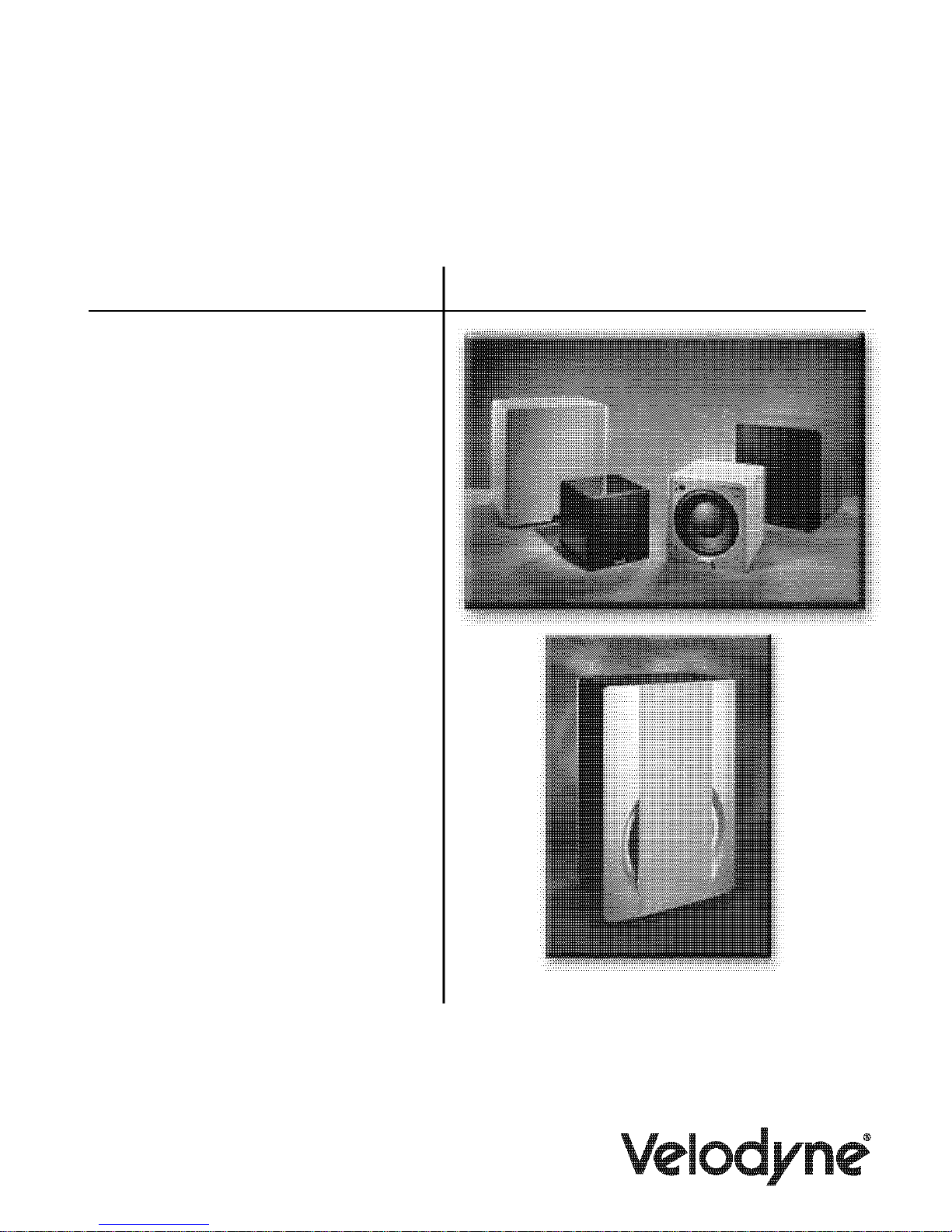
Your Velodyne Digital Drive Subwoofer consists of the following components:
• Digital Drive Subwoofer
• Power Cord
• Remote Control
• Digital Drive Accessor
- Calibrated precision microphone
- Microphone windscreen cover
- Tabletop microphone stand
- Microphone stand adapter
- 25-foot video cable
- 25-foot audio cable
- 20-foot XLR microphone cable
y Kit, consisting of:
Product Features and Controls
SUBWOOFER
Prominent features of your new Digital Drive Subwoofer include:
• Cone and Motor sizes:
- 10” (8” Piston Diameter) or 12” (9.7” Piston Diameter) cone with 310 oz. magnet or,
- 15” (12.7” piston diameter) or 18” (15.2” piston diameter) cone with 380 oz. magnet
• Built-in 1250 watt (RMS), 3,000 watt peak power high-efficiency Class-D amplifier
andem 3” voice coils
• T
• Multi-layer resin laminate cone
• High-excursion rubber surround
• Gain compression, anti-clipping circuit to prevent over excursion and amp clipping
• Fixed 80Hz high-pass crossover (RCA output)
• Balanced (XLR) input
• Line-level (RCA) inputs and thruputs
• Speaker-level inputs
ariable volume control
• V
• Frequency response of 20Hz - 120Hz +/-3dB
• Detachable 6-foot AC power cord
• Four rubber 1/4” --20” threaded suppor
on 15” and 18” models)
• On-screen controls:
- Auto-EQ
- Graphic or Parametric Equalizer controls for room EQ
- Adjustable (15 Hz - 199 Hz) low-pass crossover (defeatable)
- Multiple staggered low-pass crossovers (6dB/octave, initial to 48dB/octave, ultimate)
- Adjustable (15Hz - 35Hz) subsonic filter (defeatable)
- Multiple staggered subsonic filters (12dB/octave, initial to 48dB/octave, ultimate)
- Variable volume control
- Adjustable phase control (0° - 180° in 15° increments)
- Selectable polarity (+/-)
t feet (aluminum with rubber inserts
.
www.velodyne.com
Digital Drive User’s Manual
2

- Theater/Music selection indicator (servo speed control)
- Signal sensing auto turn on/off/12 Volt trigger (defeatable)
- 6 presets for customized listening modes and EQ defeat
- Selectable default preset
- Switchable Velodyne logo indicator
- Night Mode maximum volume setting
- Save settings indicator
- Daisy chain feature
REMOTE CONTROL
The Velodyne Digital Drive infrared remote control allows you to set up, adjust, and reset your
subwoofer when connected to a television or a video monitor. You will also use your remote to
activate preset listening values, set the subwoofer’s volume up or down, mute the subwoofer,
or set a night operational mode.
Take care not to lose or misplace your remote control as adjustments to the subwoofer (with
the exception of volume control) can only be done using the remote.
NOTE: Two 1.5V AA batteries are required and included for operation of the
emote control.
r
External IR receivers may be ordered from either V
equipment dealer.
elodyne or your local Velodyne audio
.
www.velodyne.com
Digital Drive User’s Manual
3
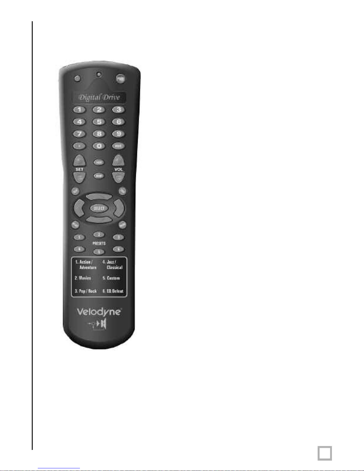
REMOTE CONTROL BUTTONS
A brief description of each button on the remote control follows:
• PWR – Causes woofer to stand by if in “Active”
standby mode.
• NUMERIC KEYP
and for other functions.
• SET (+/-) – Increases or decreases the Q value
for a parametric EQ, or sets values on the
settings page.
• LIGHT – Turns the subwoofer’s fr
logo indicator on or of
• NIGHT – Limits the peak output of the subwoofer,
and illuminates the logo’
signify that the subwoofer is in night mode.
• VOL (+/-) – Raises or lowers the volume of your
subwoofer.The blue (V
quickly as the volume increases, and the light blinks
out the volume level after you stop adjusting it. For
example, for a volume of 34, you would see three
long blinks followed by four shor
• MUTE – Mutes and unmutes the subwoofer.
• TEST – Used to toggle between the settings screen
and the system response screen during setup.
• EXIT – To exit SETUP mode. The unit will ask if you
want to save settings before exiting.
• SELECT – To toggle field values.
• RESET – Used to reset volume to the last saved
setting on the main screen, and to defeat
crossovers on the settings screen.
• MENU – Enters SETUP mode from the
introductor
• PRESETS – To access the five preset and one EQ
defeat listening modes. Initially set at the factory
they are fully user adjustable. The blue (V
light flashes the appropriate number of times to
indicate which preset you have selected (e.g. twice
for preset 2).
y screen.
AD – Used to enter SETUP mode
ont panel Velodyne
f.
s amber underlining to
elodyne) light flashes more
ter ones.
,
elodyne)
Figure 1: Velodyne Digital Drive remote control
.
www.velodyne.com
Digital Drive User’s Manual
4
o

DIGITAL DRIVE ACCESSORY KIT
The Velodyne Digital Drive Accessory Kit contains the following six components:
• Calibrated precision microphone
• Microphone windscreen cover
• Tabletop microphone stand
• Microphone stand adapter
• 25-foot audio/video cable
• 20-foot XLR microphone cable
Installation Overview
our new Velodyne servo subwoofer provides for a number of installation options. Read all the
Y
installation information below in order to determine which installation option is best for your
system. Remember to perform all installation procedures with subwoofer unplugged
until instr
SUBWOOFER CONTROLS AND PORTS
The Velodyne Digital Drive subwoofer is set up, configured, and adjusted by the controls, inputs,
and connections located on the rear panel of the unit. Figure 2 shows the location of each of
these important operational interfaces. Brief descriptions of each interface follow.
ucted to activate it!
.
www.velodyne.com
Digital Drive User’s Manual
5

Veodyne
8H--------------+
,
..
~
'"'u
....
~
.....
.
1
0
"'"
.-
..
I I
4.~
rDigita{
Signature.
•
®®®@
~
.
(Drive
""""
SPEAXER'lEY£L
r£ditio11.
.
+
u:n
tNAn
1812
~
Figure 2: Digital Drive Rear Panel Connections
.
www.velodyne.com
Digital Drive User’s Manual
6
o

(1) POWER – Press the POWER switch to the ON position to activate the subwoofer. If
the unit is to be left unused for an extended period of time, move this switch to the
OFF position to prolong the life of the subwoofer.
(2) 117V~60Hz 15A – Connect your detachable AC power plug to this male interface
connection. The detachable cord allows for easy replacement should the original
be damaged.
(3)
(4) RS-232 OUT – Use this port to communicate with a second “daisy-chained” Digital
(5) EQ Video Output – Used to display the video generated by the subwoofer. S-Video or
(6)
(7) MIC INPUT – This XLR input jack is for your XLR microphone cable.
(8)
(9) THRU – These RCA connectors are for sharing the same signal that goes into your
RS-232 IN – Use this port to communicate with your computer (for software
updates), a touch panel remote control, or another upstream Digital Drive subwoofer
See Appendix A for an explanation of the use of the serial port, available commands,
and their formats.
Drive subwoofer
irrelevant) across pins 7 and 9 of this port.
composite connections are available (composite cable included). NOTE: Only connect
to a single video output at a time.
LFE INPUT – This XLR input jack receives the balanced LFE signal from your receiver
or processor
EQ OUTPUT LEFT/RIGHT – Connect the audio cable from your accessory kit to these
jacks: white plug to LEFT
subwoofer with a second “daisy-chained” subwoofer. RCA input comes out of the
THRU jack.
. Also, the 12V trigger feature requires a 12V trigger signal (polarity
.
, and red plug to RIGHT.
.
(10)
(11) INPUT LFE – This RCA input jack is for line-level connection.
(12)
(13)
(14) SPEAKER LEVEL INPUT RIGHT/LEFT – This speaker-level connector allows either
.
www.velodyne.com
OUTPUT – These RCA connectors incorporate the use of an 80Hz 6 dB/octave slope
high pass crossover
REMOTE SENSOR – This connection allows for hook-up of the optional remote control
receiver. With the optional receiver plugged in you will be able to utilize all functions
of the remote. Place the infrared receiver within direct line of sight from your usual
listening position.
VOLUME UP/DOWN – Press the black UP pushbutton to incrementally raise your
subwoofer’
lower your subwoofer’s system volume. Note the use of these buttons during
software update.
banana plug/jack or exposed wire/terminal connections.
.
s system volume; press the black DOWN pushbutton to incrementally
Digital Drive User’s Manual
7

Installation – Quick Start
To set up and take advantage of the EQ features in your new Digital Drive subwoofer in the least
amount of time, perform the following steps:
1. Unpack the subwoofer and connect the power cable.
2. Connect an LFE input cable from your receiver/processor to the input jack.
For other hookup options, see step 2, below.
3. Power up the unit and ensure that it is receiving signal from your receiver
(i.e. playing bass).
4. Connect the microphone (in the accessory kit) and place it in your favorite listening
position. Then press 3-2-1 on the remote.
5.
The unit should emit 25 “sweep” tones then restart and play normally.
6. Adjust the subwoofer’s volume to taste.
7. Enjoy!
.
www.velodyne.com
Digital Drive User’s Manual
8

Installation – Step-by-Step
To ensure a quick and flawless installation of your Velodyne Digital Drive unit, follow these
numbered setup instructions in their exact order.
SUBWOOFER CABLE CONNECTIONS
Make all necessary cable connections between the applicable subwoofer connector port and
your particular home electronics equipment in the following order:
1. Insert the detachable AC power cord into the 117V~, 60Hz, 15A power interface port on
the rear panel of your subwoofer. Plug the male end of the cord into a convenient wall outlet.
2. Provide signal to your subwoofer through one or more of the following connections (refer to
your receiver/processor owner’s manual for available inputs to the subwoofer):
a. LFE INPUT (RCA, the RED jack at location 11 on Figure 2) – This is the most common
input cable connection. Make a connection between this input and the LFE output or
the subwoofer output of your receiver or processor; OR
LFE INPUT (XLR, location 6 on Figure 2) – Make a connection between this input and
b.
the balanced LFE outputs of your receiver or processor; OR
c. INPUT
d. SPEAKER-LEVEL INPUT (location 14 on Figure 2) – Make a connection between these
, LEFT and RIGHT (location 11 on Figure 2) – Make a connection between these
inputs and the stereo outputs of your receiver or processor; OR
inputs and the left and right speaker connections on your receiver or processor. Make
this connection by either inserting speaker wire into the correct binding post terminals
or by removing the banana plug jack caps and inserting banana plug wire into the jacks.
NOTE: Refrain from routing connections permanently at this time to accommodate subwoofer
room placement as described below
3. Establish the line-level connection (optional). Connect to a pre-amplifier’s main outputs and
returning them to your amplifier inputs. When installed in this fashion, your satellite
speakers will be crossed over at 80Hz, which removes the lower bass from your amplifier
and speakers, enabling them to do a better job reproducing high frequencies. By utilizing
this method, you will have a bi-amplified system, gaining improved power and headroom for
your system.
.
A Word About Subwoofer Outputs
The Velodyne subwoofer is designed to operate using the full range audio signal for input when
using the digital built-in crossover. Most processors/receivers have a “subwoofer out” jack that
is internally filtered and designed to be used with a conventional amplifier and speaker
rare cases, combining both an external crossover and the one internal to the subwoofer may
result in low output and increased noise. In these installations you may need to bypass the
internal crossover in either the processor or Velodyne subwoofer. In some installations, simply
setting one crossover to a higher frequency (such as 120Hz) will restore maximum
performance. To bypass the subwoofer’s internal crossover when the unit is being fed a low
pass signal from another crossover, refer to the SETUP instructions at step 14, below.
. In some
Note: If not using an external crossover, you should use the built-in crossover for
optimal per
.
www.velodyne.com
formance.
Digital Drive User’s Manual
9

4. Referring to Figure 2, Items 5 and 8, connect the audio/video cable between your
subwoofer (EQ OUTPUT VIDEO/LEFT/RIGHT yellow, white, and red respectively) and your
electronics (receiver, processor, TV, etc.). Insert the color-coded cable plugs into the correct
EQ OUTPUT receptacle – the yellow plug into the VIDEO jack, the white plug into the LEFT
jack, and the red plug into the RIGHT jack. The opposite ends of this cable should be
connected to your receiver/processor
composite video input (e.g. aux), and the white/red AUDIO (L&R) cables go to a
corresponding audio input. Consult your receiver/processor and/or TV owner’s manual for
more information.
NOTE: Make sure the audio output goes into your AUDIO system, not your TV! The subwoofer
will generate test tones used to match the subwoofer to your satellites and to correct for room
anomalies that need to be played over your main audio system.
5. Insert the XLR microphone cable’s 3-pin male plug into the MIC INPUT jack (location 7 on
Figure 2) on the back panel of the subwoofer
jack is also located on the front of the unit for convenience.
Slide the microphone (male connector end first) down through the open, circular sleeve of
6.
the tabletop microphone stand. Position this assembly at a desired listening position from
your subwoofer.
. The yellow VIDEO cable goes to an available
. For DD-15 and DD-18 units, a microphone
NOTE: The Digital Drive Accessory Kit includes a microphone stand adapter (1/2”-27 thread)
for use with professional mounting stands. Be sure to first remove the inner thread piece
(3/8”-16) before using.
7. Connect the XLR microphone cable’s female jack end with the male connector end of
the microphone.
8. Sheath the microphone pickup with the foam windscreen cover as a protection against dirt
and airborne contaminants.
A Word About Interconnect Cables
When installing your new Velodyne subwoofer using the line level connections, you should always
use shielded phono cables. There are many quality cables available today, most any of which
will work perfectly well. We do recommend that you keep the length of cable as short as
possible to avoid any potential noise problems.
When routing cables, try to keep them away from equipment that generates significant noise
such as industrial or digital equipment.
A Word About Connecting More Than One Subwoofer
If you are connecting more than one DD subwoofer to your system, you will connect them
together in a “daisy-chain.” Choose one sub for all the connections described below (we’ll call
this the “master” sub), and then connect an RCA jack from the THRU RCA jacks of the “primar
to the input jacks of the “slave” sub. You will also need to obtain a “Mouse Extension” serial
cable (available at any computer store, from your Authorized Velodyne dealer, or from Velodyne
directly) and connect the RS-232 OUT port of the primary sub to the RS-232 IN port of the
secondar
volume, etc.) will be communicated to the secondary sub automatically through the serial cable.
If you have more than two subs in your setup, simply continue the daisy chain from the
secondary sub to the next sub in the line (using both RCA and serial connections) and so on.
y sub. Then, all runtime commands directed at the primary sub (such as select preset,
y”
.
www.velodyne.com
Digital Drive User’s Manual
10

NOTE: When a DD subwoofer detects an incoming RS-232 command, it reverts to “Slave
Mode”. This means that the subwoofer will no longer accept IR commands. To reestablish
normal operations, remove the RS-232 cable and power cycle the unit.
Note that the daisy chain connection ONLY allows the woofers to communicate basic “run-time”
commands such as volume and preset. W
up daisy-chained subs.
First, connect only the master sub to the system. Do not connect the thru or serial
1.
cables at this time.
2. Establish the crossover, phase, and other settings EXCEPT the EQ on the master sub
(see setup steps 1 – 17 starting on page 17). Note the low pass crossover, phase
and polarity settings, then save.
3.
Connect the video out of the slave subwoofer, go to the settings screen, establish the
low pass crossover, slope, phase, polarity, and night mode settings from the master
subwoofer, then save settings. Repeat for each slave subwoofer in your system.
4. Connect the microphone to the slave subwoofer and use the “self-EQ” feature
(described below) to establish room EQ for that subwoofer
e recommend the following sequence when setting
.
5. Repeat steps 3 and 4 for each slave subwoofer in your system.
6. Reconnect the video out to the master subwoofer, and reconnect the thru and serial
cables so that the master and slave subwoofer (s) are daisy chained.
7. EQ the primary subwoofer (see steps 8-25 starting on page 20). Self-EQ is NOT
recommended for the primar
8. Setup is complete!
y subwoofer.
.
www.velodyne.com
Digital Drive User’s Manual
11

Subwoofer setup – Overview
BEFORE YOU BEGIN: Once the installation has been completed, note that you can use your
subwoofer without performing ANY of the setup steps below. Simply use the remote to set the
volume, and select the preset that most closely matches your listening material, and enjoy!
However, to reap the maximum benefits of Digital Drive technology, read on!
Special note for 230V users with video problems
For 230-volt Digital Drive subwoofers, the default video mode is NTSC video format. If your TV
is NTSC compatible, you will have no trouble with this mode. However, certain TVs (especially
older ones) may require PAL or SECAM video. To switch from NTSC to PAL/SECAM mode,
press the DOWN ARROW four times followed by RESET. The subwoofer will restart in
PAL/SECAM video mode. To revert back to NTSC, restore defaults by pressing 8-9-0 while on
the cover screen.
SELF-EQ
o perform an abbreviated setup of your Digital Drive subwoofer using the self-EQ function,
T
position the microphone in your listening position and connect it to the subwoofer as shown in
the installation instructions. Then, press 3-2-1 on the remote. The subwoofer emits 25
“sweep tones” that are detected by the microphone and then automatically EQs your subwoofer
accordingly
returns to normal operation. Once the self-EQ process starts, pressing the RESET button can
interrupt it.
. After the sweep tones are completed, the unit automatically saves settings and
Caution: Self-EQ resets all EQs for all presets to their default values. DO NOT use the self-EQ
feature if you plan to adjust the DD subwoofer manually as described below
.
ON- SCREEN Setup
This section describes adjusting the onscreen settings of your Digital Drive subwoofer. You will
be performing all the setup functions using the buttons of your Velodyne-supplied remote control
and seeing the results on your TV screen. Words in all uppercase letters in the setup
instructions (e.g., SELECT
selected, or the field on the screen you should be paying attention to. Remember to point the
remote control at the subwoofer, not your TV!
Use the UP, DOWN, RIGHT, and LEFT directional arrow buttons that surround SELECT to
navigate the fields of the setup screens. Settings are typically changed using the SELECT key,
followed by the UP and DOWN arrow keys. Alternatively, the SET +/- buttons can be used to
change settings. A screen field highlighted in reverse video indicates your current location on
the screen. Holding down the UP, DOWN, RIGHT, or LEFT arrow keys causes the remote to
repeat and you can then rapidly move through fields to arrive at the desired one. You should
be able to perform most of the setup process by using the four arrow keys and the
SELECT button.
Following is an overview of the screens you will be using to set up your
Velodyne Digital Drive subwoofer.
, MENU, etc.) identify the specific remote button to be pressed or
.
www.velodyne.com
Digital Drive User’s Manual
12
 Loading...