

Page 1
SET UP
SER’S MANUAL
U
LUS
Digital Drive
P
DD-10+, DD-12+, DD-15+ and DD-18+
Page 2

Enjoy.
We here at Velodyne want to thank you for selecting our product.
Get ready to experience the highest quality and amazing low-distortion
bass that Velodyne is world famous for. Relax as you enhance your
home entertainment experience with our easy setup instructions.
Welcome . . . enjoy your new Velodyne!
Page 3

SAFETY NOTICES
1
INTRODUCTION
3
3
4
5
5
6
6
6
6
7
9
11
11
11
12
12
12
13
13
Read What You Need To
Manual Conventions
PART ONE - OPERATE
Introduction
Controls & Connections
Cabinet Front
Remove Subwoofer Grille
Install Subwoofer Grille
Cabinet Back Panel
Remote Control
Features
Audio Presets
Night Mode
Active, Inactive & 12V Trigger Power Modes
Light Mode
Protection Circuitry
230V Users & TV Interface
RS-232 Serial Commands for
Controlling Subwoofer
Choose Interface to use with
26
Manual-EQ Optimization
Optimization Parameters EQ
27
31
31
32
Optimization Parameters
Parametric
Recommended Parametric Adjustment Order for
Maunal-EQ Optimization
34
RESOURCES
MAINTAIN
35
35
35
35
36
36
36
36
37
38
Protect Subwoofer from Damage
Clean
Troubleshoot
Update Software
®
Windows
Setup Program Software
Service
Packaging
Waranty
SPECIFICATIONS
15
PART TWO - CONNECT
15
Subwoofer Connections
19
Dual Inputs
PART THREE - OPTIMIZE
21
Introduction
21
Optimization Methods
21
21
21
21
21
22
24
24
24
24
24
25
Place & Play
Self-EQ
PLUS
Auto-EQ
(Recommended)
Manual-EQ
Choose Optimization Method & Options
Optimization Options
Optimize for Audio Genres
our Room
Optimize for
Optimize for
Optimize for
Y
our Audio System
Y
Your Listening Preferences
Optimize for Subwoofer Placement
Page 4

LUS
SAFETY NOTICES
igital Drive
D
P
U
ser’s Manual
SAFETY NOTICES
CAUTION: To reduce the risk of electric shock, do not remove cover (or back). No user-serviceable parts inside. Refer servicing to qualified
service personnel.
THE LIGHTNING FLASH WITH ARROWHEAD SYMBOL is intended to alert the user to the presence of uninsulated “dangerous voltage”
within the product’s enclosure that may be of sufficient magnitude to constitute a risk of electric shock to persons.
THE EXCLAMATION POINT SYMBOL is intended to alert the user to the presence of important operating and maintenance (servicing)
instructions in the literature accompanying the subwoofer.
1. READ INSTRUCTIONS — All safety and operating instructions should be read before the product is operated.
2. RETAIN INSTRUCTIONS — The safety and operating instructions should be retained for future reference.
3. HEED WARNINGS — All warnings on the product and in the operating instructions should be adhered to.
4. FOLLOW INSTRUCTIONS — All operating and use instructions should be followed.
5. WATER AND MOISTURE — The product should not be used near water — for example, near a bathtub, washbowl, kitchen sink, laundry
tub, in a wet basement, near a swimming pool or the like.
6. CARTS AND STANDS — The product should be used only with a cart or stand recommended by the manufacturer.
7. WALL OR CEILING MOUNTING — The product should be mounted to a wall or ceiling only as recommended by the manufacturer.
8. VENTILATION — The product should be situated so that its location or position does not interfere with its proper ventilation. For example,
the product should not be situated on a bed, sofa, rug, or similar surface that may block the ventilation openings; or placed in a built-in
installation such as a bookcase or cabinet that may impede the flow of air through the ventilation openings.
9. HEAT — The product should be situated away from heat sources such as radiators, heat registers, stoves, or other products that
produce heat.
10. POWER SOURCES — The product should be connected to a power supply only of the type described in the operating instructions or as
marked on the product.
11. GROUNDING OR POLARIZATION — This product may be equipped with a polarized alternating-current line plug (a plug having one
blade wider than the other). This plug will fit into the power outlet only one way. This is a safety feature. If you are unable to insert the plug
fully into the outlet, try reversing the plug.If the plug should still fail to fit, contact your electrician to replace your obsolete outlet. Do not
defeat the safety purpose of the polarized plug.
[ 1 ]
Page 5
LUS
SAFETY NOTICES
igital Drive
D
P
U
ser’s Manual
12. POWER-CORD PROTECTION — Power-supply cords should be routed so that they are not likely to be walked on or pinched by items
laced upon or against them, paying particular attention to cords at plugs, convenience receptacles, and the point at which they exit from
p
the product.
13. CLEANING — The product should be cleaned only as recommended by the manufacturer.
14. NONUSE PERIODS — The power cord of the product should be unplugged from the outlet when left unused for a long period of time.
15. OBJECT AND LIQUID ENTRY — Care should be taken so that objects do not fall and liquids are not spilled onto the enclosure.
16. DAMAGE REQUIRING SERVICE — The product should be serviced by qualified service personnel when:
a. The power-supply cord or plug has been damaged.
b. Objects have fallen or liquid has been spilled into the product.
c. The product has been exposed to rain.
d. The product does not appear to operate normally or exhibits a marked change in performance.
e. The product has been dropped or damaged.
17. SERVICING — The user should not attempt to service the product beyond what is described in the operating instructions. All other
servicing should be referred to qualified service personnel.
18. LIGHTNING — For added protection for the product during a lightning storm or when it is left unattended and unused for long periods of
time, unplug it from the wall outlet.
19. OVERLOADING — Do not overload wall outlets, extension cords or integral convenience receptacles as this can result in a risk of fire or
electric shock.
20. ATTACHMENTS — Only use attachments and accessories specified by the manufacturer.
21. VOLTAGE — Insure that the subwoofer is only connected to the rated source voltage. Do not connect the 120-volt version to 230-volts or
vice-versa.
CAUTION:
ARNING:
W
This will result in damage to the product and possible injury to the user.
o prevent electrical shock, match wide blade of plug to wide slot, fully inserted.
T
our Digital Drive
Y
PLUS
subwoofer generates a very strong magnetic field. People with pacemakers should avoid holding the
subwoofer close to their chest as many pacemakers are very sensitive. Check with your pacemaker manufacturer or physician for guidance
with your device.
[ 2 ]
Page 6

INTRODUCTION
igital Drive
D
LUS
P
U
ser’s Manual
You’ve just unpacked your Digital Drive
LUS
P
Drive
to integrate with a wide variety of audio systems. The Digital Drive
PLUS
; the most advanced and best sounding subwoofer available. Velodyne designed the Digital
LUS
P
integrates with systems consisting of classic turntables and
analog amplifiers to those with surround sound processors and digital media players. Whether you want awesome bass while watching
ovies or you’re an audiophile, the Digital Drive
m
his introduction is your road map to which parts of this manual apply to your audio system and needs.
T
PLUS
as features and optimization options to suit you.
h
READ WHAT YOU NEED TO
This manual has multiple parts, so only read those parts that you need to. This allows you to quickly set up and start enjoying awesome
bass without having to read through lots of pages that don’t apply to your type of audio system(s) or your bass optimization needs.
The rest of this introduction summarizes this manual’s sections, their goals, what’s in them and in what cases reading it is recommended.
PART ONE – OPERATE
Goal
LUS
• To help you understand the Digital Drive
Recommended If
• You want to know what Digital Drive
• You want to know how the audio genre presets impact the subwoofer’s output.
• You are unfamiliar with the uses of the input and output connectors on the back of the Digital Drive
• You are integrating your Digital Drive
components in your system.
What’s in this Part
• Description of the functions of the controls, inputs, outputs and display on the Digital Drive
• Description of the remote control button functions.
• Description of of the audio presets.
• How to remove and re-install the front grille to access the front controls.
• Description of the power modes, including standby, active and night.
• Description of the serial (RS-232) commands available for controlling the Digital Drive
P
features and how to use its inputs, outputs and controls.
LUS
P
features are available to you.
LUS
P
.
PLUS
into an advanced audio system that uses a universal remote to control all the
PLUS
.
PLUS
.
PART TWO - CONNECT
Goal
• To help you connect one subwoofer or multiple subwoofers into your existing audio system(s).
Recommended If
• Your audio system requires connections not covered in the Quick Start Guide.
ou are controlling your audio system using a 12V trigger signal, serial (RS-232) commands, or ethernet port.
Y
•
• You have a separate surround sound system in addition to your music system. For example, you have a different
amplifier, receiver or speakers you use for listening to music than you do for watching movies.
What’s in this Par
• How to connect using an LFE signal.
• How to connect multiple subwoofers using one subwoofer as a master to control the other slave subwoofers.
• How to connect separate Right and Left audio channels to your subwoofer(s).
• How to connect two audio system outputs to your subwoofer using the line-level and speaker-level connections.
• How to connect if controlling your audio system using a 12V trigger signal, serial (RS-232) commands, or ethernet port.
t
[ 3 ]
Page 7

INTRODUCTION
igital Drive
D
PART THREE – OPTIMIZE
oal
G
• To help you choose the Digital Drive
ecommended If
R
• You are unfamiliar with the Digital Drive
PLUS
optimization option and user interface that are right for you.
PLUS
optimization options for getting the best bass response for your listening
room and preferences.
You are unfamiliar with the optimization parameters for a subwoofer.
•
What’s in this Part
LUS
Comparison of the Place & Play, Self-EQ, Auto-EQ
•
Digital Drive
PLUS
subwoofers.
P
nd Manual-EQ optimization options available for
a
• Description of what subwoofer parameters you can automatically and manually customize using each optimization option.
• Description of the user interface choices for performing Manual-EQ optimization.
PART FOUR - MAINTAIN
Goal
• To help you understand the Digital Drive
Recommended If
• You want to know what how to protect your investment in your Digital Drive
• You want to register your subwoofer’s warranty.
What’s in this Part
• Listing of the safety guidelines to follow when using your Digital Drive
• Listing of the recommended maintenance and care of your Digital Drive
• Listing of service and warranty information for your Digital Drive
PLUS
safety, care, warranty and service information.
PLUS
.
PLUS
.
PLUS
.
LUS
P
.
LUS
P
U
ser’s Manual
MANUAL CONVENTIONS
Receiver: For simplicity, “receiver” is used throughout this document to refer to your audio receiver or surround sound processor. Many audio
systems use receivers, but more complicated and updated systems use surround sound processors or controllers.
[ 4 ]
Page 8

LUS
PART ONE — OPERATE
igital Drive
D
P
INTRODUCTION
his part of this manual describes how to operate your Digital Drive
T
ontrols and Connectors
C
• The subwoofer’s front and back panel controls and connectors.
• The remote control functions.
Audio preset settings.
•
• How to remove and replace the front grille to access the front panel controls.
Features
• Night, light and power modes.
• Protection circuitry.
• The serial commands available for controlling the subwoofer. Serial commands are for advanced integration of the subwoofer into
a home theater system. Usually, this is done by professional installers.
PLUS
ubwoofer and its remote control, including:
s
ser’s Manual
U
[ 5 ]
Page 9
LUS
PART ONE — OPERATE
igital Drive
D
P
U
ser’s Manual
CONTROLS & CONNECTIONS
he subwoofer is set up, configured and adjusted by the controls, inputs and connections located on the back and front panels of the
T
subwoofer and the remote. Figures 1, 2 and 3 show the location of each of these important operational interfaces. Brief descriptions of each
nterface are below.
i
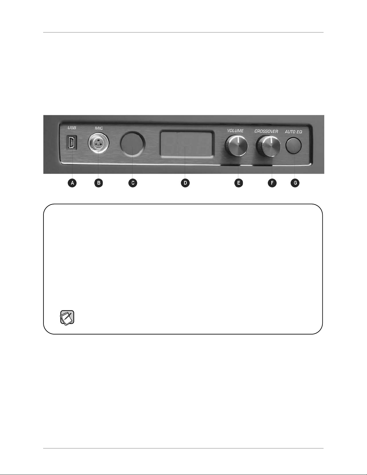
Cabinet Front
n order to access the controls and connections on the front of the cabinet, you need to remove the grille. You don’t need to remove the grille
I
right now. For instructions on how to remove and re-install the grille, see the Remove Subwoofer Grille and Install Subwoofer Grille sections.
Figure 1: Subwoofer Cabinet Front with Grille Removed
A. USB: Connect this mini USB to a
PC to optionally use the Windows
Setup Program to optimize the
subwoofer output.
B. MIC: Connect the smaller end of the
mic cable to use the microphone in
conjunction with the Sweep Tone CD.
The EQ functions will terminate unless
the microphone is connected.
C. Remote Control Sensor: Receives
remote control commands.
D. LED Display: Shows volume level,
crossover frequency and Auto-EQ
status messages. LED display is
visible through the front grille.
E. VOLUME: Adjust subwoofer output
The volume level shows
volume.
on the LED.
F. CROSSOVER: Adjust low pass
crossover frequency. The crossover
frequency shows on the LED.
LUS
P
G. AUTO EQ: Press and hold for 5
seconds to start the Auto-EQ
function. This time delay prevents
accidentally performing the
PLUS
Auto-EQ
function. “AU”
appears on the LED display
once Auto-EQ
PLUS
starts.
The volume and crossover frequency return to their saved values after a power cycle unless these settings were
PLUS
saved using the Auto-EQ
settings during Self-EQ,
software’s TV screen or PC interface. The volume and crossover knobs don’t change
Auto-EQ or Manual-EQ.
REMOVE SUBWOOFER GRILLE
To remove the grille:
1. Place your thumbs on the top outside corners of the grille.
2. Use your thumbs to gently apply downward pressure to the top outer grille edges and pull the top grille edge towards you.
3. After the top of the grille is free of the top cabinet face, carefully rock the bottom grille cups of the grille off of the steel grille pegs.
PLUS
INSTALL SUBWOOFER GRILLE
To reinstall the grille:
1. Carefully insert the bottom grille cups of the grille onto the lower steel grille pins.
2. Place your thumbs on the top outside corners of the grille.
3. Use your thumbs to gently push the top grille onto the cabinet face.
4. Push the grille to the cabinet over each grille pin.
[ 6 ]
Page 10
CONTROLS & CONNECTIONS
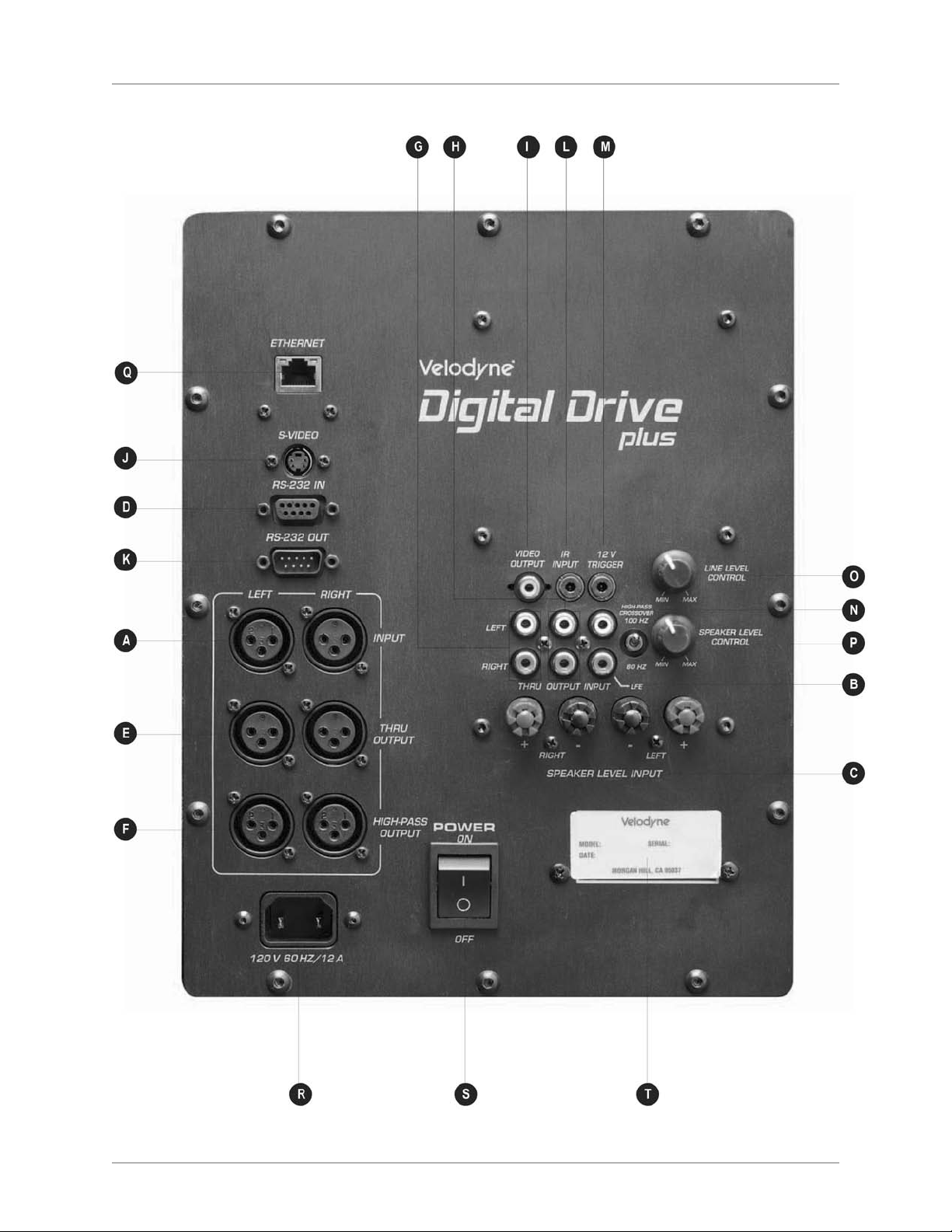
Cabinet Back Panel
igital Drive
D
LUS
P
U
ser’s Manual
Figure 2: Subwoofer Cabinet Back Panel
[ 7 ]
Page 11

CONTROLS & CONNECTIONS
igital Drive
D
LUS
P
U
ser’s Manual
LR AUDIO INPUTS
X
. LFE INPUT:Balanced XLR inputs.
A
Connect LFE or left and right balanced
XLR inputs from your receiver or
processor. Either of these inputs can
be used for an LFE signal.
RCA AUDIO INPUTS
B. LFE INPUT:
Use one of these two RCA
inputs for the LFE output from your
receiver. Or use the pair for the left and
right channel signals from your receiver.
The line-level control (O.) changes the
volume of these line-level connections.
SPEAKER LEVEL INPUTS
C. SPEAKER LEVEL:
Input for either
banana plug/jack or exposed
wire/terminal connections.
RS-232 INPUT
D. RS-232 IN:
Communicate with a
computer, a touch panel remote control
or an upstream daisy-chained Digital
PLUS
subwoofer.
Drive
XLR AUDIO OUTPUTS
E. THRU OUTPUT:
Connect subwoofer
output to downstream subwoofer in a
“daisy-chain.” Output is unfiltered L&R.
F. HIGH-PASS OUTPUT: Crossed-over
high frequency output signal to send
to a preamp. The preamp amplifies
this signal to use as the audio input
to satellite speakers. The crossover
frequency is set with the HIGH P
ASS
CROSSOVER switch.
CA AUDIO OUTPUTS
R
. THRU:Connect subwoofer output
G
to downstream subwoofer in a
“daisy-chain.” Output is unfiltered L&R.
H. OUTPUT: Crossed-over high frequency
output signal to send to a preamp. The
preamp amplifies this signal to use as
the audio input to satellite speakers.
The crossover frequency is set with the
HIGH PASS CROSSOVER switch.
VIDEO OUTPUTS
I. VIDEO OUT:
Display the video
generated by the subwoofer on
your TV using composite video.
J. S-VIDEO: Display the video
generated by the subwoofer
on your TV using S-video.
Either connect the VIDEO
OUT or the S-VIDEO
output; not both.
RS-232 OUTPUTS
K. RS323 OUT:
Communicate with a
downstream “daisy-chained” Digital
PLUS
subwoofer.
Drive
CONTROLS
L. IR INPUT: Allows for hook-up of the
optional Velodyne remote control
receiver. With the optional receiver
plugged in it will allow the remote
control to control the subwoofer even
if the subwoofer sensor is pointed away
from you. Place the infrared receiver
within direct line of sight from your
usual listening position.
. 12V Trigger: Turns the subwoofer
M
ON and OFF using a 12V signal from
receiver to control. This signal can be
either + 12V or -12V.
N. HIGH PASS CROSSOVER: Selects
the crossover frequency for the XLR
HIGH PASS OUTPUT or the RCA
HIGH PASS OUTPUT as either 80 Hz
or 100 Hz. This filter rolls off at 6 dB.
O. LINE LEVEL CONTROL: Adjust
volume level for line level input (B.)
This level control doesn’t adjust the
volume for the XLR inputs (A.).
Maximum level is with control
turned fully clockwise.
P. SPEAKER LEVEL CONTROL:
Adjust volume level for speaker level
input (C.) Maximum level is with
control turned fully clockwise.
Q. ETHERNET: To accept function
control commands from a home
automation control system.
R. Power Receptacle: Connect
detachable
AC power plug.
S. POWER: Switch power to the
subwoofer ON and OFF.
T. Serial Tag: Shows serial number,
model number and manufacturing
date for the subwoofer
.
[ 8 ]
Page 12
CONTROLS & CONNECTIONS
Remote Control
igital Drive
D
LUS
P
U
ser’s Manual
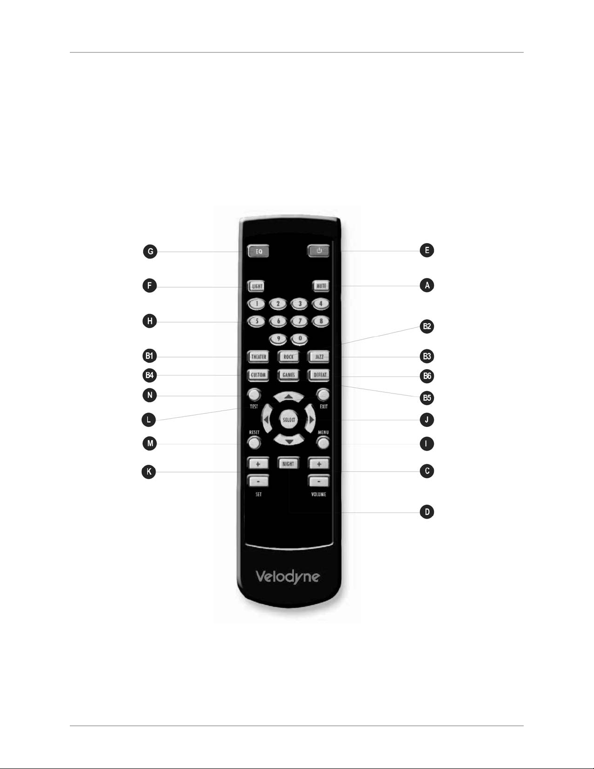
he Velodyne Digital Drive
T
PLUS
emote control allows you to:
r
• Select listening presets and night mode.
Adjust the subwoofer volume.
•
• Run Auto-EQ
Set up, adjust and reset your subwoofer when connected to a TV.
•
PLUS
.
Take care not to lose or misplace your remote control as some of the adjustments to the subwoofer can only be done using the remote.
Figure 3: Remote Control
[ 9 ]
Page 13

CONTROLS & CONNECTIONS
igital Drive
D
LUS
P
U
ser’s Manual
Listening Controls
A. MUTE:
Mutes and unmutes the
subwoofer. You can use this to toggle
between how your audio system sounds
with and without the subwoofer playing.
PRESETS: Accesses the five presets
and one EQ defeat listening modes.
he presets are set at the factory,
T
but you can adjust them.
B1. THEATER: EQ boost at 37 Hz.
B2. ROCK: EQ boost at 52 Hz.
B3. JAZZ: No EQ boost —
reference listening.
B4. CUSTOM: Set to your
listening preference.
B5. GAMES: EQ boost at 60 Hz.
B6. DEFEAT: Use to toggle between
another preset being on and off
to listen to the sound difference.
C. VOLUME + and -- : Raises or lowers
the volume of your subwoofer.
Other Controls
Toggles the subwoofer between
E. :
active and standby modes if power
switch on back of subwoofer is ON.
F. LIGHT: Changes the LED display
operation between momentary on
(default) and constantly on. The
olume level is readable even with
v
the front subwoofer grille in place.
Optimization Controls
LUS
G. EQ:
Performs Auto-EQ
P
. If Setup
parameters have been saved from
either an Auto-EQ or Self-EQ, pressing
LUS
P
this button won’t run Auto-EQ
again
unless you hold the button down for
about 5 seconds. This is to prevent
PLUS
Auto-EQ
from running and overwriting any manual settings you
have saved if this button is
accidentally pushed.
H. Numeric keypad: Enters Setup mode,
enters Self-EQ mode and starts
other functions.
Optimization Controls for
EQ Set Up Using a TV Screen
I. MENU: Enters SETUP mode from the
introductory screen.
J. SELECT: Toggles field values.
K. SET + and -- : Increases or decreases
he Q value for a parametric EQ or
t
sets values on the Settings screen.
L. EXIT: Exits Setup mode.
M. RESET: Resets volume to the last
saved setting on the Systems Settings
screen and defeats the crossovers
on the Settings screen. Also exits
from any EQ process to the
Introductory screen.
N. TEST: Toggles between the
Settings Screen and the
System Response screen.
D. NIGHT: Limits the peak volume of
the subwoofer to a percentage of
the selected preset volume or
volume.
SETUP
[ 10 ]
Page 14

LUS
FEATURES
igital Drive
D
P
U
ser’s Manual
FEATURES
udio Presets
A
The subwoofer comes with six audio presets, five of which are pre-programmed at the factory. The preset or preset’s numbers and their
orresponding labels on the remote are shown in the table below.
c
• Presets 1, 2, 3 and 5 are shipped from the factory with predetermined settings.
• Preset 4’s contour level is set at 0 from the factory and is customizable by the user.
Preset 6 defeats all the EQs to demonstrate the effect the equalization of the subwoofer has on the sound quality.
•
ecause movies, rock, pop and games may already have their bass emphasized in the recordings, using these presets may cause too much
B
low frequency boost for your listening preference. As such, the presets are offered purely to be used to personal taste and are not required for
the various source types.
DEFAULT PRESET SETTING
Number Contour Contour
(System EQ EQ Default
Settings Label on Frequency Boost Volume Suggested Preset Use
Screen) Remote Boost at Level* Level & Description
1 Theater 37 Hz 3.0 34 Movies. Volume is slightly louder than
for the Jazz preset.
2 Rock 52 Hz 2.0 33 Rock and Pop music. Volume is slightly
higher than for the Jazz preset.
3 Jazz 35 Hz 0.0 30 Jazz and Classical music. This is the most
neutral with no boost at any frequency or
overall volume increase.
4 Custom 35 Hz 0.0 30 For you to make a custom boost frequency and level.
5 Games 60 Hz 2.5 33 Video Console and Online Game Playing.
olume
Gunfire and explosions sound better
. V
is slightly higher than for the Jazz preset.
6
Defeat
35 Hz
0.0 30 Defeats all EQs. Use to toggle between what
your system sounds like with and without EQ.
*The boost level is proportional to dB. That is, a boost of 5.0 is greater than a boost of 3.0. For no boost use 0.0. The boost frequency and
level are controlled by the contour frequency and contour level settings.
Night Mode
Night mode lowers the subwoofer volume by specifying a compression to a percentage of the overall volume level.
The factory set, default
percentage for this setting is 30%. You might want to use night mode during times when you want to enjoy your sound system but you don’t
want to disturb your neighbors or other people in your house who are sleeping or need quiet time.
You can toggle night mode on and off using the
• You hear a volume change.
And either “
•
n” then the volume level or “n OFF” appears on the front LED display
NIGHT button on the remote control. When toggling night mode:
.
[ 11 ]
Page 15

LUS
FEATURES
igital Drive
D
P
U
ser’s Manual
If using the video output display, night mode shows as active below the Preset note on the Introductory screen. Night mode can be modified in
the “Next” page of either the video output menu or the Windows Setup Program.
ctive, Inactive & 12V Trigger Power Modes
A
The subwoofer has three power ON modes. These modes help the user control power conservation when the subwoofer isn’t playing,
ut allow the subwoofer’s power switch to remain ON at all times.
b
• In the active mode, the subwoofer’s standby mode is on. When the subwoofer gets an audio signal input, the internal amplifier turns on
to play the audio. It takes a few seconds for the DSP processor to boot-up and then you hear the audio.
• If the subwoofer is in active mode and doesn’t receive an audio signal, the subwoofer automatically goes into standby mode to save
power. This takes between 10 to 15 minutes.
• In standby mode, the subwoofer’s power switch is ON and its internal amplifier isn’t on.
If the subwoofer will be left in standby for a period of greater than 5 days,
Velodyne recommends turning off the power switch.
• In the inactive mode, the standby mode is defeated.
• In the inactive mode and when the subwoofer power switch is ON, its internal amplifier is on even if the subwoofer isn’t receiving
an audio signal.
If the subwoofer will be left inactive for a period of greater than 5 days,
Velodyne recommends setting the power switch to OFF.
• In the 12V trigger mode, the subwoofer turns on with a 12V source (from a controlling receiver) at its 12V trigger jack.
• In 12V trigger mode and when the subwoofer’s power switch is ON, its internal amplifier isn’t on until it receives 12V in either polarity
at the 12V trigger jack.
• In 12V trigger mode, if the 12V trigger is not applied, the subwoofer will not respond to the remote control. To reset the mode, apply the
trigger and then use the remote or Windows Setup Program to effect the change.
If the subwoofer will be left inactive in 12V trigger mode for a period of greater than 5 days,
Velodyne recommends setting the power switch to OFF.
Light Mode
When the light mode is OFF, the LED display behind the front grille is always off, except when momentarily lit to show a change in the volume
PLUS
or crossover settings or the status of the Auto-EQ
does reflect changes in crossover settings or the status of the Auto-EQ
process. When light mode is ON, the LED display always shows the volume, except it
PLUS
process and then reverts to volume. Having the LED on at all
times can be distracting in a darkened listening room, so the default setting is OFF.
Protection Circuitry
The subwoofer is equipped with protection circuitry to provide maximum performance with greatest reliability. The subwoofer is
protected against:
• Overdriving the speaker
• Overdriving the amplifier
• Overheating the amplifier
• Excessive drop in power line voltage
[ 12 ]
Page 16

LUS
FEATURES
igital Drive
D
P
U
ser’s Manual
The overdrive protection circuitry operates constantly without being audible under most situations.
If the subwoofer should shut down, reduce the volume setting and shut the subwoofer off until it cools down. The time the subwoofer takes
o cool down depends on the ambient room temperature, but typically at least 10 minutes are required for the subwoofer to cool down and
t
recover from the thermal shutdown.
Also, try plugging the unit into a different wall socket. Overloaded sockets or damaged home wiring circuits can cause power voltage drops
while the subwoofer is drawing high power levels. This condition can result in the subwoofer shutting down intermittently.
230V Users & TV Interface
LUS
For 230-volt Digital Drive
P
subwoofers, the default video mode is NTSC video format. If your TV is NTSC compatible, you will have no
trouble with this mode. However, certain TVs (especially older ones) may require PAL or SECAM video. To switch from NTSC to PAL/SECAM
mode, press the DOWN ARROW four times followed by RESET. The subwoofer will restart in PAL/SECAM video mode. To revert back to
NTSC, restore defaults by pressing 8-9-0 while on the video output Introductory screen.
RS-232 Serial Commands for Controlling Subwoofer
This section describes the RS-232 protocol specification and commands that can be used to control the subwoofer. This protocol indicates
LUS
P
how Digital Drive
subwoofers receive run-time commands from devices such as Crestron®products.
The communication protocol uses the standard communication settings for the COM port as shown below.
COM Port Settings
Baud Rate 9600
Data Bits 7 or 8
Parity None
Stop Bits 1
PLUS
The Digital Drive
serial ports use a standard configuration that allows direct connection to a PC via a FEMALE to MALE DB-9
RS-232 serial extension cable. Only three pins are required as shown below.
IN Pin OUT Pin
2 Transmit 2 Receive
3 Receive 3 Transmit
5 Ground 5 Ground
If you are having trouble communicating with your Digital Drive
PLUS
subwoofer, check your serial cable first.
It may be a null modem or “crossover” cable, which won’t work for communicating with the subwoofer
Serial commands should be formatted as shown below.
RS-232 SERIAL COMMAND FORMATS
Byte Number
Byte Description Notes
.
0 ‘#’ Header character
1 to 3 or 1 to 4 Command and 3 to 4 ASCII characters. See the RS-232 Serial Command
Parameter Data table below. These characters must be in CAPS as the
commands are case sensitive.
This character is required or command
4 or 5
ermination character
‘$’
T
.
is ignored.
[ 13 ]
Page 17

LUS
FEATURES
igital Drive
D
P
The serial commands are shown below.
RS-232 SERIAL COMMANDS
Activity Command Format Acceptable n Values Examples Comments
Volume #VOnn$ 00-99 #VO25$, Sets volume to a value
#VO+$ #VO+$ Increments volume up
VO-$ #VO-$ Increments volume down
#
#VO?$ #VO?$ Requests current volume setting
Preset #PSn$ 1 , 2, 3, 4, 5, 6 #PS4$ Activates the indicated preset
#PS?$ #PS?$ Requests the current preset
Light Mode #LTn$ 0, 1 #LT0$ Activates light mode
#LT?$ #LT1$ Deactivates light mode
#LT?$ Requests light mode state
Night Mode #NMn$ 0, 1 #NM1$ Activates night mode
#NM0$ Deactivates night mode
#NM?$ #NM?$ Requests night mode state
ser’s Manual
U
Mute #MUn$ #MU0$ Un-mutes subwoofer
0, 1 #MU1$ Mutes subwoofer
#MU?$ #MU?$ Requests mute state
Power #LTn$ 0, 1 #LT1$ Turns power on
#LT0$ Turns power off
#LT?$ #LT?$ Requests power state‘$’
[ 14 ]
Page 18

PART TWO — CONNECT
How to Connect Using an LFE Signal
RCA LFE Connection:
igital Drive
D
LUS
P
U
ser’s Manual
XLR LFE Connection:
[ 15 ]
Page 19

CONNECT
igital Drive
D
How to Connect Multiple Subwoofers Using One Subwoofer as Master to Control
the Other Slave Subwoofer
LUS
P
U
ser’s Manual
How to Connect Separate Left and Right Audio Channels to Your Subwoofer
Left & Right RCA Connection:
[ 16 ]
Page 20

CONNECT
Left & Right Speaker Level Connection:
igital Drive
D
LUS
P
U
ser’s Manual
NOTE: Be sure to connect + to + and - to -. Do not leave any wire strands loose at the connection.
Left & Right XLR Connection:
[ 17 ]
Page 21

CONNECT
igital Drive
D
How to Connect Two Audio System Outputs to Your Subwoofer Using Line Level
and Speaker Level Connections
Line Level & RCA Connection:
LUS
P
U
ser’s Manual
NOTE: Be sure to connect + to + and - to -. Do not leave any wire strands loose at the connection.
How to Connect if Controlling your Audio System Using a 12V Trigger Signal
or Serial (RS-232) Commands
12V Trigger Connection:
[ 18 ]
Page 22

CONNECT
igital Drive
D
LUS
P
U
ser’s Manual
Connect the Digital Drive
The Digital Drive
o a single system.
t
uidelines for using this feature:
G
PLUS
has dual inputs; line-level RCA and speaker-level. You can use these dual inputs for dual systems and dual connections
PLUS
using Dual Inputs
• Adjust the input level from each system for proper balance.
The line-level and speaker-level controls on the subwoofer’s back panel act as attenuators, so you can turn down the feed
•
from the system with the higher level.
• If NOT using dual inputs, then set both level controls on the back panel to MAX.
• The XLR inputs bypass these input level controls, but you can still adjust the speaker-level input down to match the
XLR input, if the speaker-level signal is greater than the XLR-signal level.
Dual Systems
The Digital Drive
PLUS
allows for connection into two audio systems at one time; one through the line-level RCA inputs and one through the
speaker-level inputs. This makes the setup easy for sharing the subwoofer with a surround system and a 2-channel music system.
Dual Connections
Some listeners find an audible benefit in simultaneously connecting a subwoofer’s line-level and speaker-level connections to the same
receiver
. To easily make these simultaneous connections:
PLUS
PLUS
.
.
1. Connect the speaker-level connection from the receiver output to the speaker-level input on the Digital Drive
2. Connect the LFE (or L+R) line-level signals from your receiver to the line-level input on the Digital Drive
These dual connections aid in filling in the missing mid-bass in single systems with thin mid-bass. The single-system connection runs the
LUS
Digital Drive
the Digital Drive
P
subwoofer off of the signal voltage applied to the satellites, but modified by the satellite impedance. This connection allows
LUS
P
subwoofer to more naturally and seamlessly blend with your satellite speakers. If you feel your system’s mid-bass is thin
based on your listening preferences, use dual connections and evaluate if your system’s mid-bass sounds better.
Connect into a Dual System
To share the Digital Drive
PLUS
using its dual inputs for dual systems:
1) Connect the 2-channel music system to the subwoofer’s speaker-level inputs. Follow the connections in the Connect section.
Be sure to connect + to + and – to –.
2) Connect either the LFE signal or the line-level left and right signal from the surround system to the subwoofer
s line-level RCA
’
input
depending on the system type and connection availability.
Choose which system requires the more critical alignment. Which one will you listen to more or which one requires the more precise
3)
alignment? W
4) Listen to both systems with the line-level and speaker-level controls on the back of the Digital Drive
e refer to this as the primary system and the other as the secondary system.
PLUS
at MAX (knobs
all the way to the right).
5) Turn the subwoofer volume up so that both systems at least match the main speaker output and sound fairly balanced in level.
6) Turn down the level control (line or speaker) on the system that has too much bass compared to the main speakers when
that system is running.
urn the secondary system off.
T
7)
urn on and optimize the primary system using Place & Play, Self-EQ, Auto-EQ
T
PLUS
, or Manual-EQ.
See how to perform these optimization procedures in the Optimize section.
urn off the primary system and turn on the secondary system. It should be close to the correct level, but you can adjust a little
T
8)
more if you want. Do not change the primary system’s level control or you will have to start from Step 4 again.
Be sure to play only one system at a time. Be sure to at least turn off the preamp and power amp or receiver of the second system.
Playing both systems at the same time can result in damage to the audio components in both systems.
[ 19 ]
Page 23

CONNECT
igital Drive
D
Connect with Dual Connections into a Single System
To use the Digital Drive
) Connect the speaker-level inputs as shown in the Connect section. Be sure to connect + to + and – to –.
1
PLUS
dual inputs to make dual connections for a single system:
2) Connect the LFE signal to the subwoofer’s RCA LFE input connector.
) In the receiver, set the bass management options to “large” or “full range front left and right speakers.” If the receiver
3
has an option to add LFE to those channels, select this option as well.
) Turn the subwoofer’s speaker-level control to MIN (knob all the way to the left).
4
5) Turn the subwoofer’s line-level control to MAX (knob all the way to the right).
6) Run the system in your primary mode (surround or 2-channel).
7) Optimize the system using Place & Play, Self-EQ, Auto-EQ
PLUS
, or Manual-EQ. See how to perform these optimization
procedures in the Optimize section.
8) Run the system in the other mode.
9) Turn the subwoofer’s speaker-level control up until the mid-bass is to your liking.
LUS
P
U
ser’s Manual
[ 20 ]
Page 24

LUS
PART THREE — OPTIMIZE
igital Drive
D
P
U
ser’s Manual
OPTIMIZATION INTRODUCTION
This part of this manual first explains the optimization methods and nomenclature. To help you choose a method, this section then describes
the capabilities of each method as well as the time each optimization requires to complete. Next, to help you choose how to perform your
elected optimization method, this part describes the optimization software interfaces available, including the Window Setup Program and
s
your TV screen.
To help you understand the parameters you can optimize, this section then discusses each how each parameter affects the subwoofer’s bass
output. Finally, this part recommends the basic methodology for performing Manual-EQ optimization.
OPTIMIZATION METHODS
LUS
The Digital Drive
P
subwoofer offers the Place & Play, Self-EQ, Auto-EQ
to refer to all the subwoofer’s parameters that can be changed to equalize how the subwoofer sounds throughout its frequency range. You
choose what is right for you although Velodyne recommends Auto-EQ
(not including setup time) and doesn’t require you to install and use the Velodyne-authored Windows Setup Program on your Windows
computer or the TV-screen interface to manually modify the bass frequency response.
Place & Play
Place & Play setup doesn’t require the use of the supplied microphone. You can get great sounding bass from the factory-default EQ settings
with the ability to use the default preset EQ settings for different audio genres.
LUS
P
and Manual-EQ optimization methods. EQ is a shorthand way
LUS
P
as it automatically gives you great sounding bass in about 5 minutes
Self-EQ
Self-EQ is the simplest and fastest way to optimize the bass response from your subwoofer for your room. Self-EQ adjusts the levels of eight
parametric EQs only. Unlike Auto-EQ and Manual EQ, which use the sweep tone on the enclosed CD and can adjust all settings on the
subwoofer, Self-EQ uses a sweep tone generated from the subwoofer itself which is picked up using the calibrated microphone. Self-EQ
smoothes the frequency response of the subwoofer from 15 to 120 Hz and leaves the settings for volume, crossover, slope and phase
unchanged.
Auto-EQ
Auto-EQ
subwoofer and audio system. During the Auto-EQ
microphone and the Auto-EQ
response. The Auto-EQ
PLUS
(Recommended)
PLUS
is recommended by Velodyne. Auto-EQ
PLUS
sweep tone (found on the enclosed CD) played through your system to optimize the low frequency output
PLUS
system first automatically mutes the subwoofer to determine the low frequency response (<200 Hz) of the
PLUS
is the most advanced way to automatically optimize the bass response from your
PLUS
process, the Auto-EQ
PLUS
digital signal processing algorithm uses a calibrated
speakers in your audio system. After finding this response, the subwoofer unmutes itself and matches its output to the satellites while
maintaining a smooth blend with the satellite’s low frequency output. Auto-EQ
PLUS
then adjusts the output level, the frequency response,
the crossover filter parameters, and the output phase, but only adjusts the parametric filters for level.
Manual-EQ
Manual-EQ is the most customized way to optimize the bass response from your subwoofer.
The Auto-EQ
PLUS
optimizes in a manner that
sounds great for many people. However, we at Velodyne understand that everyone has unique listening preferences and that there are
thousands and thousands of receiver, processor, speaker and room combinations. Hence, the Digital Drive
PLUS
Auto-EQ
Manual-EQ optimization with the settings from the Auto-EQ
system are designed to support custom EQ settings through the Manual-EQ process. We recommend you start your
PLUS
optimization as a starting point for you to further tune the Digital Drive
PLUS
subwoofers and the
PLUS
subwoofer to your preference. You can optimize the subwoofer for the preset levels, crossover filter parameters, and phase as well as the
full parametric filter parameters.
Manual-EQ also uses the
Auto-EQ sweep tone played through your system, but also requires you to use the V
Setup Program on your Windows computer or the
elodyne-authored Windows
TV-screen interface to manually modify the bass frequency response.
[ 21 ]
Page 25

LUS
OPTIMIZATION
igital Drive
D
P
U
ser’s Manual
CHOOSE OPTIMIZATION METHOD & OPTIONS
ith Digital Drive
W
options the Auto-EQ
Your room acoustics
•
• Your audio system
• Your listening preferences
Different audio genres
•
Use the table below to choose an optimization level.
Below the table are short explanations of what you can optimize for; audio genres, your listening room, your audio system and your
listening preferences.
PLUS
ou choose the level of subwoofer performance optimization that is right for you. The optimization level determines what
y
PLUS
system optimizes for, including:
[ 22 ]
Page 26

OPTIMIZATION
igital Drive
D
LUS
P
U
ser’s Manual
PLUS
1
Manual-EQ
able Connection,
C
SUBWOOFER PERFORMANCE OPTIMIZATION METHOD
Place & Play Self-EQ Auto-EQ
minutes 10 minutes 15 minutes 25 minutes
8
Receiver Setup,
Program Installation
Clean Up Time
&
Optimization Time
0 minutes 2 minutes 5 minutes 30 minutes
Optimization Options Audio genres Room Room, audio system, Room, audio system,
& listening preferences & listening preferences
Parameters Optimized Contour filter Contour filter Subwoofer Subsonic filter
frequency and frequency and volume frequency and slope
level (boost) level (boost)
Contour filter Polarity
Parametric frequency and
filter levels level (boost) Subwoofer volume
Parametric Contour filter frequency
filter levels and level (boost)
Parametric
filter levels
Crossover filter Crossover filter
frequency and slope frequency and slope
Phase Phase
Parametric filter bandwidths and frequencies
Servo gain
(music to theater)
Optimization Level Average Medium Highly Customized
Requires Microphone No Yes Yes Yes
& Mic Connections
Requires Auto-EQ
PLUS
No No Yes Yes
Sweep Tone CD
Requires TV or Windows
No No No Yes
2
Setup Program
Requires Knowledge of
No No No Yes
Frequency Response Curves
and Filter Parameters
Time if Use the “Crawl >20 >20 >20 >20
Test” Technique minutes
3
minutes
3
minutes
3
minutes
to Optimize
Subwoofer Placement
[ 23 ]
3
Page 27

LUS
OPTIMIZATION
igital Drive
D
P
U
ser’s Manual
1 Setup and optimization times are approximate and for one subwoofer.
2 We recommend using the Windows Setup Program as making the USB connection between the front of the subwoofer and the laptop is
uch easier than having to access the composite video or S-video input connection on the back of your TV. Also, with the Auto-EQ
m
PLUS
software you can see the changes to the frequency response on the same screen as the one on which you’re changing parameters.
he Setup Program requires a computer with Windows
T
®
P, Vista or 7.
X
3 Actual time depends on the number of locations at which you listen to or look at the frequency response of the subwoofer.
OPTIMIZATION OPTIONS
Optimize for Audio Genres
You might prefer to have a different bass sound and feel that depends on the type of audio you’re listening to. For example, if you’re gaming
versus if you’re watching a movie. Having presets that are accessible on the remote control allows you to easily optimize for these different
audio genres without any additional setup by you. And you don’t have to use the presets for the type of audio on the remote control buttons.
For example, if you like how your Jazz music sounds using the Pop preset better than the Jazz preset, use the Pop preset. If you’re feeling
a bit more adventurous, you can even modify these presets to your exact tastes using the TV or Windows interfaces.
Optimize for Your Room
As a subwoofer plays in a room, the reflections of the sound waves off the walls create standing waves. Standing waves cause places in the
room where certain frequencies are louder and others are diminished. Some room cancellations of the sound waves can be like black holes
that no amount of amplifier power can fill. Thus, as a general rule it is better to “cut down” a peak of the frequency response rather than to
PLUS
“boost up” a valley. Self-EQ and Auto-EQ
perform this adjustment automatically for you.
In general, you should try to achieve a frequency response that is +/– 3 dB at all lower frequencies. This is because most people perceive a
response curve of this accuracy level as very smooth. However, people with excellent hearing or who have been trained to listen for sonic
purity can hear frequency response deviations to as small as +/- 1 dB or less. The Digital Drive
PLUS
automatically smooth your Digital Drive
subwoofer to within a +/- 3dB window.
PLUS
Self-EQ and Auto-EQ
PLUS
both will
Optimize for Your Audio System
How good your bass sounds also depends on how smoothly it blends with the output of the satellite speakers. If a smooth transition doesn’t
exist at the crossover frequency, you hear either too much mid-bass or the bass frequencies as separate from the mid and high frequencies.
To smoothly blend the subwoofer with the main speakers, you first need to know the low frequency response of the main speakers.
PLUS
Auto-EQ
determines the low frequency response of the main speakers automatically and blends with it.
The response always rolls off at the lowest end, but no dip or peak should exist at the crossover frequency with the satellites. While the goal
is a perfectly flat response, this may not be possible in the higher frequencies of the subwoofer’
s response due to peaks or valleys introduced
by the satellites.
Optimize for Your Listening Preferences
Everyone has a personal preference as to how they want their audio system to sound. With the Self-EQ and Auto-EQ
PLUS
features, the bass
response for your subwoofers in your listening room should be within +/– 3 dB. These EQ methods aren’t as aggressive as they could be as
optimizing filters for flatter response takes exponentially longer due to perturbing external noises to the process. Also, using more EQ can
sometimes have a negative ef
fect in the time domain, so less EQ is preferable.
PLUS
, you can make the correcting filters more aggressive or adjust it in other ways to match your listening preferences.
However
Auto-EQ
serves as an excellent starting point for those of you who want to manually adjust parameters to modify the frequency response profile and
[ 24 ]
Page 28

LUS
OPTIMIZATION
igital Drive
D
P
U
ser’s Manual
the parametric filter frequencies, bandwidths and levels. It’s your subwoofer, not ours any more. You have the freedom to make it sound the
way you want it to.
ptimize for Subwoofer Placement
O
When you unpack the subwoofer, you place it in the room according to the information in the general section and optionally the ”Crawl
est” section in the Subwoofer Placement Recommendations Guide. The “Crawl Test” can help you to improve the bass reproduction quality
T
by simulating moving the subwoofer around the room using acoustic reciprocity to find the placement that gives you the sound you like
best. With the ”Crawl Test” you have to move around the room. Moving yourself around is easier than moving a heavy subwoofer around.
If you want to use the ”Crawl Test”, do so before performing any of the optimization methods.
Room placement is one step to equalize the subwoofer(s) to the room. Subwoofers operate at extremely low frequencies, which are primarily
omni-directional. Hence; you can’t usually tell where the bass is coming from. Finding the best location for your subwoofer in your room is a
trial and-error process.
With the ”Crawl Test” Technique:
• You find the best tradeoff between appearance of the subwoofer in the room and the subwoofer sound quality.
• You optimize the subwoofer placement when the room is in the configuration that it is in when you typically listen, such as doors opened
or closed, curtains open or closed, etc. Additionally, you can learn what effect the configuration has on bass quality, by changing it and
listening or measuring.
PLUS
• You can rely just on what you hear to pick a location or you can use the microphone and Auto-EQ
sweep tone with the subwoofer set
to Manual EQ to look at the frequency response graphs to see which location is best.
Your satellite speakers also contribute to how your audio system sounds. If moving your satellites is an option, you might likewise place them
through experimentation and measurement.
[ 25 ]
Page 29

LUS
OPTIMIZATION
igital Drive
D
P
U
ser’s Manual
CHOOSE INTERFACE TO USE WITH MANUAL-EQ OPTIMIZATION
his section is an overview of the subwoofer optimization interface options so you can choose which to use for Manual-EQ optimization.
T
You can perform Manual-EQ optimization using either the TV or Windows Setup Program interface. The Setup Program comes with your
igital Drive
D
If you want to use the Auto-EQ, Self-EQ or Place & Play method, you won’t need to use either, so you can skip this section. However, if you’re
urious to see the low frequency response output of your audio system using Auto-EQ, you can view it with both of these interfaces.
c
Velodyne Recommendation Preferred Use if you don’t have a Windows XP, Vista or
Time to Setup Fast. Doesn’t require access Depends on how accessible the video input connector is
PLUS
nd needs to be installed on a Windows XP, Vista or 7 computer.
a
NTERFACE CHOICES FOR THE MANUAL-EQ OPTIMIZATION METHOD
I
indows Computer TV Screen
W
to TV video input. on your TV. With many entertainment systems, the TV’s
7 laptop or desktop computer
composite video or S-video input may be difficult to
reach because it is usually on the back of the TV close
to a wall. Also, the video input is often already connected
to another video component.
Equipment Required Windows laptop or desktop computer TV with composite video or S-video input
Operating System Requirements Windows XP, Vista or 7 (MAC OS N/A
and Linux OS not supported)
Software Required The included Setup Program N/A
installed on the Windows computer
[ 26 ]
Page 30

OPTIMIZATION
OPTIMIZATION PARAMETERS EQ
igital Drive
D
LUS
P
U
ser’s Manual
The following table describes the subwoofer EQ parameters that are either automatically configured with Auto-EQ
hese parameters can be manually customized by you using the Manual-EQ method.
t
PLUS
and/or Self-EQ. All of
EQ Parameter Set with Set with Description
LUS
Auto-EQ
P
Self-EQ
Low Pass Crossover Yes No The upper limit of your subwoofer’s frequency response.
Frequency and Slope The crossover frequency can be set to increments of 1 Hz,
between 40 Hz and 199 Hz or it can be disabled
(-- or OFF). The crossover slope can be set to 6, 12, 18,
24, 30 or 36 dB/octave.
Typically, these parameters are the same for all the
presets however you can choose to vary the values in
the different presets.
For Self-EQ the crossover frequency is set to 160 Hz
with a slope of 24 dB.
The subwoofer crossover frequency can also be changed
by the subwoofer’s front panel control. Please note that this
type of change is temporary until you change it and save it
to the DD+ using either the TV or Windows interface.
Subsonic Filter No No Sets your subwoofer’s lowest frequency limit in
Frequency and Slope increments of 1 Hz between 15 Hz and 35 Hz.
The subsonic filter slope can be set to 6, 12,
18 or 24 dB/octave.
Usually, the subsonic filter doesn’t need to be changed from
its default of 15 Hz with a steep roll off of 24 dB. The default
settings provide the maximum protection at the widest
bandwidth. Increasing the crossover frequency protects the
subwoofer more; lowering the slope protects it less.
If your subwoofer isn’t adequately protected at very low
frequencies, you can blow up the subwoofer’s amplifier or
cause other damage that requires subwoofer replacement,
which are very expensive repairs.
It is easier to overdrive the subwoofer at these low
frequencies because you can’t hear these frequencies.
Warped vinyl records can have unexpected output at very
low frequencies and damage the subwoofer. Some CD’s
are made without filtering this part of the signal out.
[ 27 ]
Page 31

OPTIMIZATION
igital Drive
D
LUS
P
U
ser’s Manual
EQ Parameter Set with Set with Description
PLUS
Auto-EQ
Self-EQ
Adjust the subsonic filter if your media requires it or if peaks
nd valleys exist at the very lowest frequencies that you
a
can’t correct using room placement of the subwoofer and/or
arametric filter adjustment. Use of a lower slope at the
p
lowest crossover frequency should be done only
intermittently to extend the life of your Digital Drive
PLUS
subwoofer. The proper setting for these parameters is
dependent on playback level and size of the room.
Experiment carefully and choose the correct setting
for your usage.
Typically, during Manual-EQ these parameters are the same
for all the presets. However if your media is so demanding
and varied for different listening modes, you might want to
set these filters individually for each preset.
Phase Yes No Adjust the phase delay of your subwoofer’s output signal
from 0° to 180° in 15° increments to allow a better blend to
the satellites at crossover and account for distance or delay
differences. During Manual-EQ, we recommend you adjust
the polarity before adjusting the phase.
Polarity No No Your subwoofer’s polarity can be either positive (+) or
(+/-) negative (-). Toggling between these settings reverses the
audio signal’
s phase 180 degrees. This can be helpful with
extreme placements, certain crossover slopes or blending
to main speakers driven by amplifiers with inverted polarity.
Volume Yes Yes During Manual-EQ, you can set the volume level from 1 to
(1-99) 99 for each preset (1-5) separately from the Setup preset
(the 0 or global preset) volume. The Setup preset volume
can be changed permanently or temporarily using the
Windows and TV screen interfaces or temporarily using the
volume control on the remote or the volume knob on the
front of the subwoofer
. If the change made by the volume
control on the front or on the remote is desired to be
permanent, you must enter either the TV screen interface’s
setup menu or the Windows Setup Program and select to
save and exit. Otherwise, the new volume setting will be
lost upon turning off power to the subwoofer.
[ 28 ]
Page 32

OPTIMIZATION
igital Drive
D
LUS
P
U
ser’s Manual
EQ Parameter Set with Set with Description
Auto-EQ
PLUS
Self-EQ
The factory default presets include volume difference from
the Setup preset volume per the character of the preset.
This difference helps identify the preset audibly, but can be
hanged. Each preset increments its volume in accordance
c
with any changes of the subwoofer volume, keeping these
ifferences intact. For example, if the subwoofer is set to
d
the Jazz preset (preset 3) and shows a volume of 30
because the Setup preset volume is 30 and the Theater
preset (preset 1) volume is 40, selecting preset 1 raises the
volume to 40. If the VOL+ key on the remote is then used to
increase the volume to 45, and then the Jazz preset (preset
3 – same level as the Setup preset) is selected, the
subwoofer will display a volume of 35. These volume
differences can be seen in the preset volume line in the
TV screen and Windows interfaces.
Contour Frequency No No Frequency that can be set in increments of 1 Hz between
15 Hz and 200 Hz to boost or cut the signal (contour) of
your subwoofer‘s frequency response at that frequency.
The contour filter acts as an “extra” user-set EQ that can
be used to manipulate the subwoofer frequency response
when a particular preset is invoked. The subwoofer’s Setup
preset parameters don’t include those for the contour
filter as each contour filter is a subset of each of the
other presets.
Contour Level No No A preset’s contour filter’s amount of boost or cut added at
the contour frequency. + 6 dB is the maximum boost.
-13 dB is the maximum cut. The contour level is like
changing the volume at only one bass frequency.
Theater / Music Indicator No No Sets the accelerometer servo gain of the digital servo
system between 1 and 8. The 1 setting is for the least
amount of servo gain or allowing some distortion; this
setting might be more appreciated for media with less
accuracy required, such as movies or games. The 8 setting
is for the most amount of servo gain or least amount of
distortion; this setting would be used more for critical
listening of music. We prefer using 8 for the theater preset,
but feel free to customize it if you like.
The somewhat higher distortion of the 1 setting during
playback makes explosions and other theatrical and gaming
content have an overall louder and more impressive bass
[ 29 ]
Page 33

OPTIMIZATION
igital Drive
D
LUS
P
U
ser’s Manual
EQ Parameter Set with Set with Description
LUS
Auto-EQ
P
Self-EQ
response. The lowest distortion setting of 8 lowers the
overall perceived level because of the elimination of
distortion products, producing a very tight and “fast”
ounding bass – well suited for listening to music. Numbers
s
in between yield a result either more towards the one end
r the other. You can determine the best setting by listening.
o
The subwoofer’s setup preset parameters don’t include this
setting as it is like the contour: different for each preset.
The factory setting for the presets are:
• N/A for the setup preset
• 8 (least distortion) for Theater (Preset 1)
• 6 (low distortion) for Rock (Preset 2)
• 8 (least distortion) for Jazz (Preset 3)
• 8 (least distortion) for Custom (Preset 4)
• 3 (moderate distortion) for Games (Preset 5)
• 8 (least distortion) for Defeat (Preset 6)
Default Preset No No This is the preset used when your subwoofer is powered on
from the off state. The factory setting is preset 3. This
preset can be set to any one of the presets using either the
TV screen interface or Windows setup interface. When the
standby mode is used from the remote (red button), the
preset stays the same as the last setting and does not
revert to the default setting.
[ 30 ]
Page 34

LUS
OPTIMIZATION PARAMETERS
igital Drive
D
P
U
ser’s Manual
OPTIMIZATION PARAMETERS
Parametric
he following table describes the three parameters of the eight EQ filters that can be adjusted during the optimization process of the
T
PLUS
Digital Drive
subwoofer. The parametric filters can help you to achieve better room equalization. Although the Auto-EQ
optimization processes automatically adjust the level of the preset parametric filters, only the Manual-EQ allows adjustment of the frequency
nd bandwidth, as well as level of these filters.
a
he parametric filters should be adjusted after the system parameters have be set.
T
During the Manual-EQ process, remember that all of the preset parameters are available for adjustment. At this time, you can customize each
preset to get the appropriate character for use with differing satellites or media depending on your needs and system complexity
PLUS
and Self-EQ
EQ Setting Set with Set with Set with
Self-EQ Auto-EQ
LUS
P
Manual-EQ Description
Frequency (F) No No Yes The center frequency for the parametric filter. The parametric filters
should be placed at peaks and valleys in the frequency response during
Manual-EQ optimization. You should put a filter at the highest peak first
and adjust the filter levels before proceeding to put filters at the next
highest peak. You should put filters at the peaks before putting filters at
valleys. Remember that you are using up amplifier headroom when you
raise a dip, so it is better to lower a peak.
When manually setting the filter frequencies, avoid putting more than
one filter at one frequency. The filters can be close, but if you find that
you need to stack the filters at one frequency, you have probably placed
the subwoofer or microphone in a poor location in the room near or at a
null. To correct for this RESET the subwoofer using the remote, move
the location of the subwoofer or mic and start over with the Auto-EQ
optimization and then proceed back into Manual-EQ.
The default parametric filters are at the 1/3 octave ISO frequencies:
20 Hz, 25 Hz, 32 Hz, 40 Hz, 50 Hz, 63 Hz, 80 Hz and 100 Hz.
PLUS
Level (L) Yes Yes Yes The filters can be adjusted in level between +6 dB and -13 dB.
The default level is 0 for all filters.
Bandwidth (Q) No No Yes The bandwidth determines how narrow the parametric filter is.
The narrower the filter, the higher the Q value and the faster the roll
off on each side of its center frequency.
The default Q setting for the
bandwidth is 4.3 The Q can be set between 0.1 and 20. The Q or
bandwidth of the filter is usually adjusted last after correctly setting
the frequency and level. It is adjusted so that as little around the dip
or peak being corrected is affected.
[ 31 ]
Page 35

LUS
RECOMMENDED PARAMETERS
igital Drive
D
P
U
ser’s Manual
RECOMMENDED PARAMETER ADJUSTMENT
ORDER FOR MANUAL-EQ OPTIMIZATION
he recommended order for modifying parameters during Manual-EQ is described below. As you make changes observe the frequency
T
response and how the system sounds to you to evaluate the impact of each parameter change.
or examples of the Manual-EQ optimization process see the Digital Drive
F
or Manual-EQ optimization:
F
1. Perform Auto-EQ
PLUS
optimization to get a good baseline to start your Manual-EQ optimization. During the Auto-EQ
PLUS
ser Interface Manual.
U
PLUS
optimization,
note the rolloff frequency and slope of your satellites when the subwoofer mutes itself. If you miss the mute of the subwoofer during
LUS
the Auto-EQ
P
process, you can still see it by pushing the Mute button once you are running Manual-EQ.
2. Start Manual-EQ. Don’t forget to have the Sweep Tone CD playing.
3. Allow the subwoofer and CD signal to sync.
4. Once synced, make sure that you are in the Setup preset. If you want to change a different preset, make sure you are in that one,
but remember that any changes to the preset parameters will no longer be global as when done with the Setup preset. Because of
this, we recommend that you perform your Manual-EQ in the Setup preset.
PLUS
5. If you missed noting the rolloff frequency and slope of your satellites during the Auto-EQ
optimization, push the Mute button in
the Windows Setup Program or on the remote control. Note the rolloff frequency and slope of your satellites.
6. Examine the results of the Auto-EQ
PLUS
optimization for low-pass crossover frequency, low-pass slope, and phase.
7. Choose to use these settings or adjust to match the values you arrived at from the muting step. Bear in mind that these settings
PLUS
may not match the measurement of your satellites because Auto-EQ
measures and compares actual averages of the summed
subwoofer-to-satellite frequency response. It is worth writing them down or remembering them in case you change them to match
the satellites and find that you cannot get a smooth and reasonably flat response.
8. Adjust polarity. Some crossover combinations and some equipment require you to invert the polarity of your Digital Drive
subwoofer and you cannot achieve a reasonably flat response unless you do.
9. If you feel that the volume should be changed, do so now.
10. Begin by modifying the crossover frequency, mentally comparing how minimal dips are as well as how linear the overall response
is. Sometimes it is easiest to compare character to either side of the current setting. Leave it at the best setting.
11. Next, change the crossover slope with the same consideration in mind. Leave it at the best setting.
12. Similarly, change the phase. If you have achieved a smooth response but have a large dip at the crossover still, you should
probably start with a setting of 90° as the crossover blend may be in quadrature.
13. Because crossover frequency, slope, and phase are interrelated, it is best to adjust the crossover, slope, and phase one more time.
14. Now is the time to work the parametric filters to smooth the response. Change to the first page of either the System Response
screen in the TV screen interface or the Frequency Response and Parameters screen in the Windows Setup Program. These are
the screens that show the frequency response graph.
The following sub-steps describe adjusting these filters using the Windows
Setup Program. If you’re using the TV screen interface, use the appropriate remote control buttons to adjust the filters instead of
the mouse.
a. Locate the peaks in the response and order them from largest to smallest.
b. Use your mouse to click the diamond-shaped frequency marker for the EQ filter with the frequency closest to that of the
largest peak. Drag the frequency marker horizontally to the frequency of the peak and then down in level. A horizontal
line with a diamond-shaped marker at each of its ends appears at the EQ’s minimum. This horizontal line is the filter’s
bandwidth control.
c. Use your mouse to click one of the bandwidth markers and horizontally drag it in or out to adjust the EQ width. Try to find
the value that performs the least modification to the frequency response nearby the peak. Keep in mind that large lumps
are still peaks; they just have a wider bandwidth (or lower Q).
d. Continue to the next highest peak, repeating Steps 14a through 14c.
LUS
P
[ 32 ]
Page 36

LUS
RECOMMENDED PARAMETERS
igital Drive
D
P
U
ser’s Manual
e. If any dips are of higher concern than the rest of the peaks, then proceed to use Steps 14a through 14c for those, but pull
the EQ filter marker up in level.
f. Proceed cautiously with the dips, as you are very likely to find one or more that cause you to want to put multiple filters
ery near each other to get “enough boost”. This will be a null, which can show very little change after applying a lot of
v
acoustic power at its particular frequency. It is best not to EQ these very much.
5. Now you can modify the settings for the presets if you want. The most common settings to focus on for preset adjustment are the
1
preset contour frequency, contour level and the Theater/Music setting. However, if you want to change the crossover frequency,
crossover slope, phase and polarity for each preset, you should do so now following the procedure outlined in Steps 8 and
Steps 10 through 13.
16. If you are using the Windows Setup program, exit Manual-EQ by clicking Save and Exit. If you are using the TV screen interface,
select Exit/Save in the upper right of the screen and then select Yes to save.
17. Stop the Sweep Tone CD.
18. If you are using the Windows Setup Program, keep it open. If you are using the TV screen interface, push 1-2-3-4-5 on the remote
and then press Select quickly after.
19. If you are using the Windows Setup Program, wait for it to reconnect to the subwoofer. If you are using the TV screen interface,
the subwoofer is already connected to the TV.
LUS
20. Play the appropriate media through the Digital Drive
P
subwoofer for the preset you want to change. Proceed to modify contour
frequency, contour level and the Theater/Music settings.
a. For each preset, decide upon a frequency for the contour. Set the contour level to somewhere between 2.0 and 4.0 so
you can hear the change. Listen to your media and adjust the contour frequency until the contour is boosting the correct
frequencies to your taste.
b. Then adjust the contour level to your taste. These values are proportional to, but not equal to a dB.
c. While listening to the media, change the servo gain, or Theater/Music setting. A setting of 8 has the most gain and the
PLUS
lowest distortion as noted previously, while 1 has the least gain. Even in the 1 setting, the Digital Drive
subwoofers
have lower distortion than conventional subwoofers. Select the setting that yields the best appropriate accuracy for
your media.
21. At this point, you can adjust the subsonic filter and subsonic filter slope. Adjust them with preservation of dynamic headroom in
mind for dynamic media with little content below 20 Hz and maximum extension for media with extreme extension, but little
dynamic need. The factory default setting works well in most cases. If you are playing content that is particularly dynamic with little
sub-20 Hz content, it is wise to raise the frequency. Media with extremely low bass content but little dynamics may be better
reproduced with a lower slope.
22. Finally, adjust the volume for your new presets to match the appropriate satellites or lend the correct character to your playback.
23. Make sure you save your settings before leaving the Windows or TV screen interfaces or powering off the subwoofer using the
Save to DD+, Save, Save As…, or Save To File commands for the Windows program or Save/Exit and Yes for the TV screen
interface. If you don’t save your changes, they are lost when you exit Manual-EQ or the subwoofer turns of
f.
[ 33 ]
Page 37

LUS
RESOURCES
igital Drive
D
P
U
ser’s Manual
RESOURCES
What to do if Your Surround Sound System Also Does Equalization
ost surround sound systems also perform an automatic optimization of your system. You probably have already done this for your existing
M
PLUS
system. When you add in the Digital Drive
. Place your subwoofer in its permanent location.
1
LUS
2. Run the Digital Drive
atellites to use during its automatic equalization process. If you run the sound system automatic equalization routine before you get
s
P
Auto-EQ
the blend correct, the sound system equalization algorithm may turn the subwoofer way down or up due to a peak or dip where the
subwoofer blends to the speakers.
3. Run the surround sound automatic equalization after the Digital Drive
subwoofer was added to the system. The surround system automatic equalization now has a smoothly blended bass region for
measurement and should now make the correct choices during its run.
However, due to different automatic equalization systems having different algorithms, you might want to experiment with the opposite
approach; running the surround sound equalization process first and then the Digital Drive
equalization processes gives sound that is most pleasing to you. Also be sure to examine your final settings to be sure that you didn’t end
up with your sound system’s LFE channel set very low or very high and that the level at the Digital Drive
compensate. Ideally the channel level will be somewhere near 0 dB and the Digital Drive
subwoofer, we recommend you:
LUS
P
. This gives the surround sound system a nicely bandpassed bass output for blending well to the
LUS
P
Auto-EQ
LUS
P
even if you have previously run this before the
PLUS
EQ. You can compare which order of the
PLUS
subwoofer is the opposite to
PLUS
subwoofer level at or below 50 or 60.
[ 34 ]
Page 38

LUS
MAINTAIN
igital Drive
D
P
U
ser’s Manual
MAINTAIN
Protect Subwoofer from Damage
O NOT PUT HEAVY OBJECTS or other objects ON TOP of the subwoofer cabinet that could scratch or dent the cabinet.
D
DO NOT ALLOW OBJECTS TO FALL INTO, OR LIQUIDS TO SPILL ON, THE SUBWOOFER CABINET.
DO NOT EXPOSE SUBWOOFER TO DRIPPING OR SPLASHING FROM LIQUIDS.
DO NOT PLACE LIQUID-FILLED OBJECTS ON OR NEAR THE SUBWOOFER. Examples of liquid-filled objects include flower vases,
beverages and liquid-fueled lamps.
DO NOT OPERATE THE SUBWOOFER NEAR ANY BODIES OF WATER: BATHTUBS, SWIMMING POOLS, LAKES, ETC.
DO NOT OPERATE THE VELODYNE Digital Drive
PLUS
SUBWOOFER OUTSIDE OF BUILDING STRUCTURES.
DO NOT PUSH FOREIGN OBJECTS OF ANY KIND into the subwoofer or connector openings, other than the proper cables.
DO NOT PLACE BURNING CANDLES, INCENSE, OR SMOKING PRODUCTS ON TOP OF OR NEAR THE SUBWOOFER.
DO NOT PLACE A LAPTOP COMPUTER ON TOP OF THE SUBWOOFER. Damage could occur to either the laptop hardware or the
subwoofer finish.
Clean
USE A CLEAN, SOFT DAMP CLOTH to remove dust or fingerprints from the subwoofer cabinet. Unplug the subwoofer power cord from the
power outlet before cleaning to prevent static electricity from damaging the subwoofer during cleaning.
DO NOT CLEAN THE SUBWOOFER CABINET with detergents, soaps, abrasives, aerosol sprays, chemical solvents, alcohol, or other
cleaning solutions.
Troubleshoot
SUBWOOFER ISN’T PLAYING
1. Verify unit is plugged in and power outlet used is active.
2. Verify the power switch is on.
3. Verify the subwoofer is connected to a source and all 12V triggers are on.
erify the subwoofer can produce sound. A
V
4.
good way to test this is to press 3-2-1 on the remote control while pointing
it at the IR sensor on the subwoofer. The woofer should play the sweep tone used for room Self-EQ.
IF THE BASS DOESN’T
SOUND LOUD ENOUGH TO YOU:
1. Increase the subwoofer’s VOLUME level.
2. Increase the receiver’s LFE or SUB OUT volume level, if it is adjustable.
3. Put the subwoofer closer to a corner of your room.
IF THE SUBWOOFER OUTPUT IS DISTORTED, INTERMITTENT OR STOPS:
The subwoofer may have shut down due to the protection circuitry
.
1. Reduce the volume setting; or
2. Shut the subwoofer of
f until normal operating conditions return.
[ 35 ]
Page 39

LUS
MAINTAIN
igital Drive
D
P
U
ser’s Manual
TV SHOWS DISTORTED COLORS.
Some TVs are particularly sensitive to stray magnetic fields. If your TV shows distorted colors after installing your subwoofer, simply increase
the distance between your TV and your subwoofer until normal color returns.
POOR VIDEO QUALITY on SETUP SCREENS on TV
any new receivers and AV processors support HDMI connectivity and can up-convert legacy source material to true high definition 1080i/p
M
LUS
output. If you're having difficulty currently seeing the video from your Digital Drive
P
subwoofer, go into the receiver's setup menu and select
a lower output resolution. You may also find that it's helpful to use a composite to S-video adaptor to help in this process and go into your
receiver using the S-video input. Doing so eliminates one step in the video processing chain. Or use the Windows Setup Program and PC to
avoid having to use TV screen for setup.
OTHER ISSUES see SERVICE BULLETINS and FAQs
The
Support > Service Bulletins and Support > FAQs pages of www.velodyne.com also contain information about setting up
your subwoofer.
Update Software
At the heart of Digital Drive
P
functionality is the customized software. From time to time, Velodyne publishes updates to the Digital Drive
P
LUS
Windows Setup Program software.
LUS
You can register at
www.velodyne.com to be notified by email when software updates are available.
Windows®Setup Program Software
To update the software:
www.velodyne.com.
1. Go to
2. Go to the
Support > Downloads >Software Updates page.
3. Click the icon to download the Windows Setup Program software.
4. Enter your contact information.
5. This downloaded file is an .exe file that is run from your local Windows laptop or desktop computer.
Service
DO NOT
ONL
ATTEMPT TO SERVICE THE SUBWOOFER YOURSELF beyond what is described in this owner’s manual.
USE QUALIFIED SERVICE
Y
TECHNICIANS T
O REPAIR DAMAGED PARTS. Service the subwoofer using qualified service
technicians when:
power cord or plug is damaged
A
•
The power socket on the subwoofer is damaged
•
• Objects have fallen into the subwoofer or liquid has spilled into the subwoofer
• The subwoofer was rained on or has become partially or fully submerged in water
• The subwoofer does not operate normally or exhibits a marked change in performance
• The cabinet has been dropped or is damaged
• The subwoofer driver’s cone and/or suspension is physically damaged
Packaging
Save the carton and packing materials for future use. Using other packaging for this unit may result in severe damage when shipping or
moving. You can use this packaging should you ever move or need to return the subwoofer to Velodyne for service. To save storage space,
you can flatten the box and put the other packing material in a plastic bag.
[ 36 ]
Page 40

LUS
WARRANTY
igital Drive
D
P
U
ser’s Manual
FOR YOUR RECORDS. . .
Date Purchased _____________________________________________________________________________________
Dealer ______________________________________________________________________________________________
Serial # ____________________________________________________________________________________________
*NOTE: Please complete and return your warranty card within ten (10) days or
Register. . . ON LINE . . . It’s faster . . . and easier www.velodyne.com
LIMITED WARRANTY - U.S. AND CANADA ONLY
VELODYNE ACOUSTICS, Inc. (“VELODYNE”) warrants all electronics for a period of three years, drivers for a period of five years, and full range
speakers for a period of five years. All VELODYNE products have a warranty from the date of purchase against defects in materials and
workmanship subject to the following conditions:
1. VELODYNE is not responsible for defects which result from the use of an amplifier or controller other than the one originally supplied
with the unit (subwoofer) or defects which result from modifications or repairs made by any component of the system by anyone other
than a VELODYNE factory authorized service representative.
2. This warranty is void if any repairs or service covered by the terms of this warranty are made to any component of the system by
anyone other than a VELODYNE factory authorized service representative.
3. VELODYNE is not responsible for damage caused by accidents, abuse, misuse, natural or personal disaster or unauthorized
modification. The VELODYNE products are not intended for professional or commercial use and VELODYNE is not responsible for
damage resulting from such use.
4. The VELODYNE product warranty is limited to units that are purchased from authorized VELODYNE dealers and finalized within
authorized dealer locations.
5. This warranty is nontransferable under any condition.
Use of this product outside the U.S. and Canada voids this warranty
6.
.
TO OBTAIN SERVICE
Information regarding service may be obtained from the dealer from whom you purchased the unit, or by contacting VELODYNE customer
service. Warranty service must be performed by a VELODYNE factory authorized service representative within the warranty period set forth
above. If VELODYNE determines the unit is defective, VELODYNE will, at VELODYNE’s option, repair or replace the product at no charge if
the product is forwarded prepaid to a factory authorized service representative. Products forwarded to the factory authorized service
representative should be shipped securely and properly packaged, insured and freight prepaid.
AND CANADA
TES
ARRANTY
W
OUTSIDE THE UNITED ST
A
The Warranty of this product if it is sold to a consumer outside of the United States or Canada shall comply with applicable law and shall be the
sole responsibility of the distributor that supplied this product. To obtain any applicable warranty service, please contact the dealer from which
you purchased this product, or the distributor that supplied this product.
[ 37 ]
Page 41

SPECIFICATIONS
igital Drive
D
LUS
P
U
ser’s Manual
[ 38 ]
Page 42

Velodyne Acoustics, Inc.
345 Digital Drive
Morgan Hill, CA 95037
408.465.2800 voice
408.779.9227 fax
408.465.2851 service voice
408.779.9208 service fax
www.velodyne.com
Service E-mail: service@velodyne.com
General E-mail: help@velodyne.com
Other trademarks or registered trademarks are property of their respective owner.
63-161 Rev A NOV10
 Loading...