

Page 1
Firmware Version v1.6
Revision Date March 23, 2016
Page 2
Contents
INTRODUCTION 3
FEATURES 4
INSTALLATION 5
BATTERIES 6
USE RECHARGEABLE BATTERIES 6
KNOW WHEN TO RECHARGE OR REPLACE YOUR BATTERIES 6
BUTTONS 7
MODES 8
START MODE 9
TIMER 9
DISTANCE-TO-LINE 9
DISTANCE-TO-LINE BAR GRAPH 9
RACE MODE 10
SPEED 10
HEADING 10
LIFT/HEADER BAR GRAPH 11
CONFIGURATION 12
COMPASS DECLINATION 12
GPS DATA STORAGE 12
Page 3
UNDERSTANDING DISTANCE TO START LINE 13
SETTING ENDS 13
ANIMATED DEMONSTRATION 13
OPERATION 14
ACQUIRE A GPS SIGNAL 14
SHOW OFF YOUR MAXIMUM SPEEDS 15
KEEP YOUR HAND ON THE TILLER 15
SET THE START LINE 16
USE THE TIMER 17
HOW TO SET COMPASS DECLINATION AND BOW OFFSET 18
FIRMWARE UPDATE 19
SOFTWARE 19
VELOCITEK CONTROL CENTER 19
VELOCITOOL 19
MAINTENANCE 20
CONTACT 21
COMPLIANCE 22
FCC COMPLIANCE STATEMENT 22
CANADIAN COMPLIANCE STATEMENT 22
EUROPEAN COMMUNITY COMPLIANCE STATEMENT 22
INDEX 23
Page 4
Introduction 3
Introduction
When we started brainstorming about the ProStart, we asked sailors which functions they actually use
on the SC1, the predecessor to the ProStart. What was surprising to us was that no one used VMG
function and everybody used the distance-to-line function.
A light bulb went off in our heads and we decided to design the ProStart around the distance-to-line
function. Every bit of our effort was focused on making the distance-to-line feature easy to use,
effective and communicate clearly.
The result is the best distance-to-line tool ever.
Page 5

Introduction 4
Features
Only essential features actually used by professional sailors are included in the product.
Speed, compass, and distance to line updated twice a second
Count down start timer
Header/Lift indicator updated twice a second
Maximum and best 10 second average speed recall
Over 30 hours of GPS data storage at a record rate of every 2 seconds
Over 15 hours of battery life
Data download through USB link
User configurable magnetic declination
Internet updatable firmware allows you to benefit from ongoing product improvements and
feature additions
Waterproof (IPX8) to 3m
Page 6
Installation 5
Installation
The ProStart can be installed anywhere on the boat with a view of the sky.
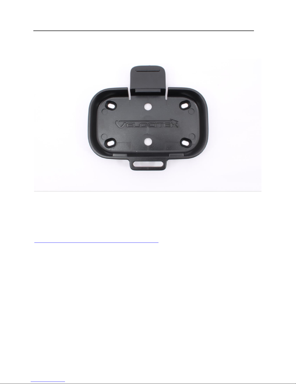
The ProStart comes with a cradle that interlocks with it. Install the cradle permanently on your boat.
Press the tab on the cradle to unlock the ProStart from it.
Several mounting options are available. For details, go to
http://www.velocitek.com/products/mounting-hardware.
Page 7
Batteries 6
Batteries
The ProStart requires 3 AA batteries to operate. The battery compartment can be reached by opening
the back of the case. The batteries are not included with the ProStart.
Use Rechargeable Batteries
We recommend using rechargeable NiMH AA batteries over standard alkaline disposable AA batteries.
Both disposable and rechargeable batteries will provide approximately 15 hours of life. Be
environmentally responsible by using rechargeable batteries instead of disposable batteries.
Know When to Recharge or Replace Your Batteries
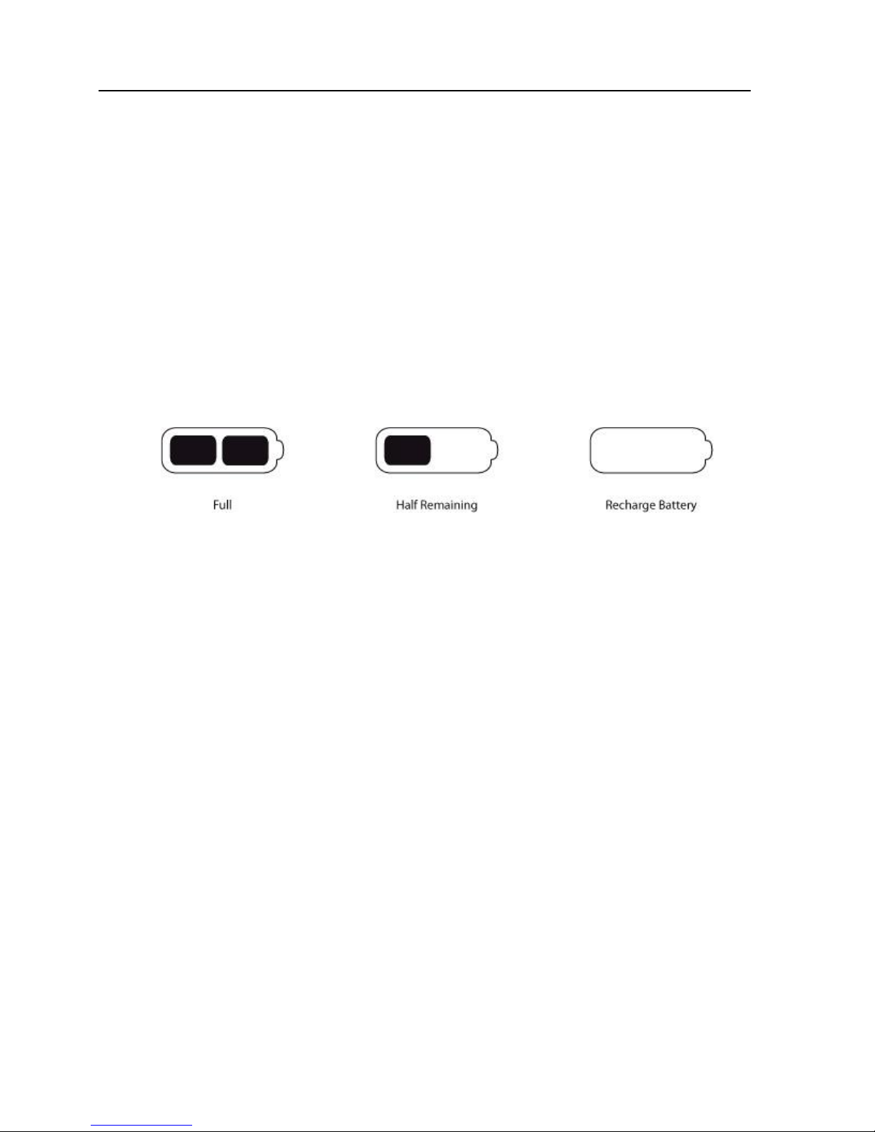
The battery indicator is located on the bottom of the LCD screen. With disposable batteries, there will
be a tendency for the life indicator to remain full for most of the battery life and only drop down to the
lower levels when the batteries are nearly exhausted.
Page 8
Buttons 7
Buttons
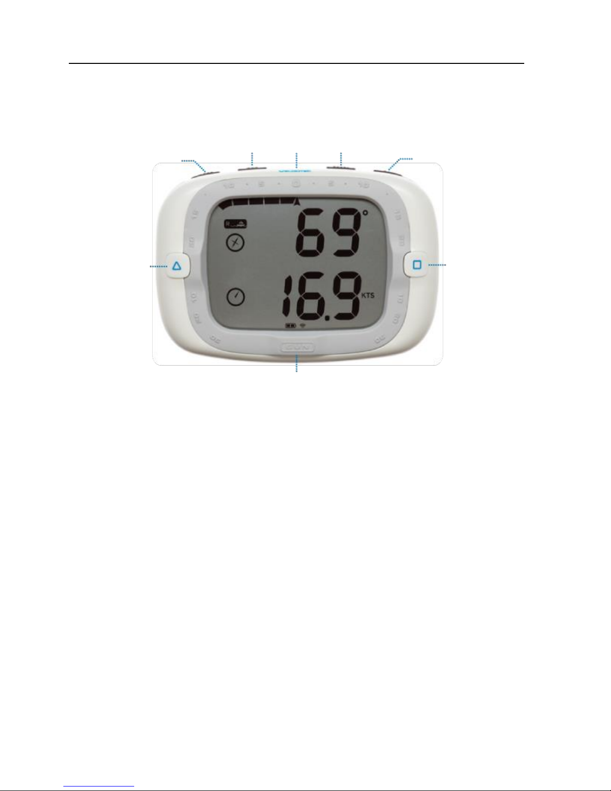
There are a total of 8 buttons on the ProStart as illustrated above. The buttons will be referred to in
capitalized blue text throughout this document as follows, PWR, MODE, MAX, RESET, +1, PIN, RC and
GUN.
Pin
Sets current
location as
pin end of
start line
Mode
Max Speed
On/Off
Timer Reset
Timer +1
Gun
Timer Start/Sync
Race Committee
Sets current
location as
boat end of
start line
Page 9
Modes 8
Modes
The ProStart function is separated into two modes each providing you with the essential information at
different stages of the race, before and after the gun.
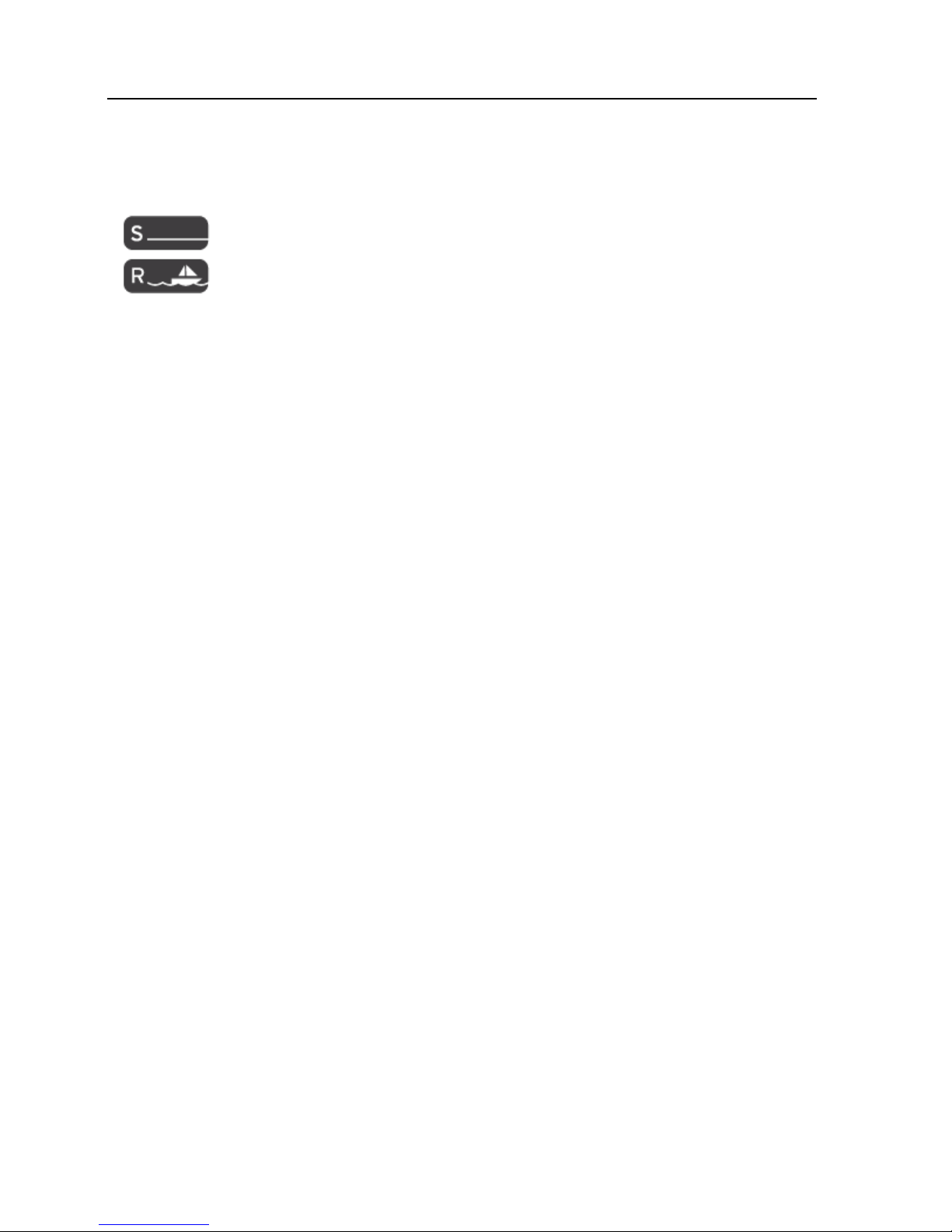
The mode indicator can be found at the upper left hand corner of the LCD screen.
Start Mode: timer & distance
Race Mode: speed & heading
Page 10
Modes 9
Start Mode
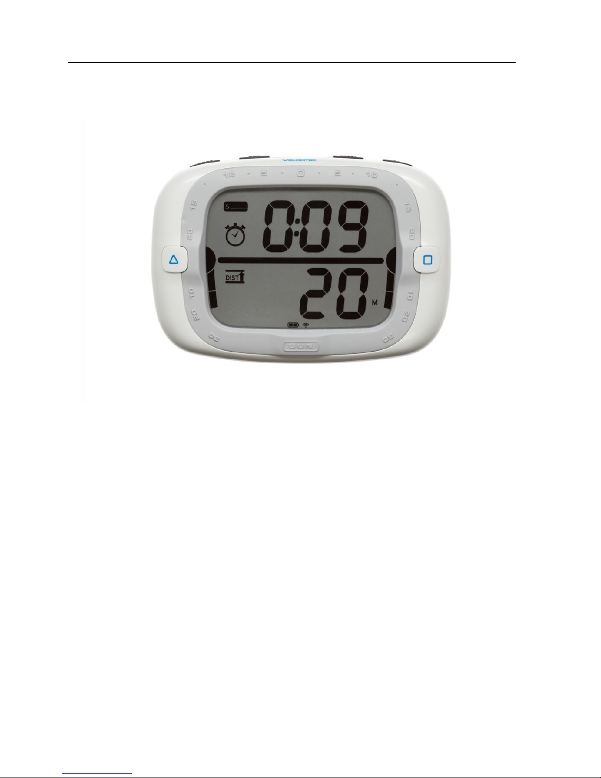
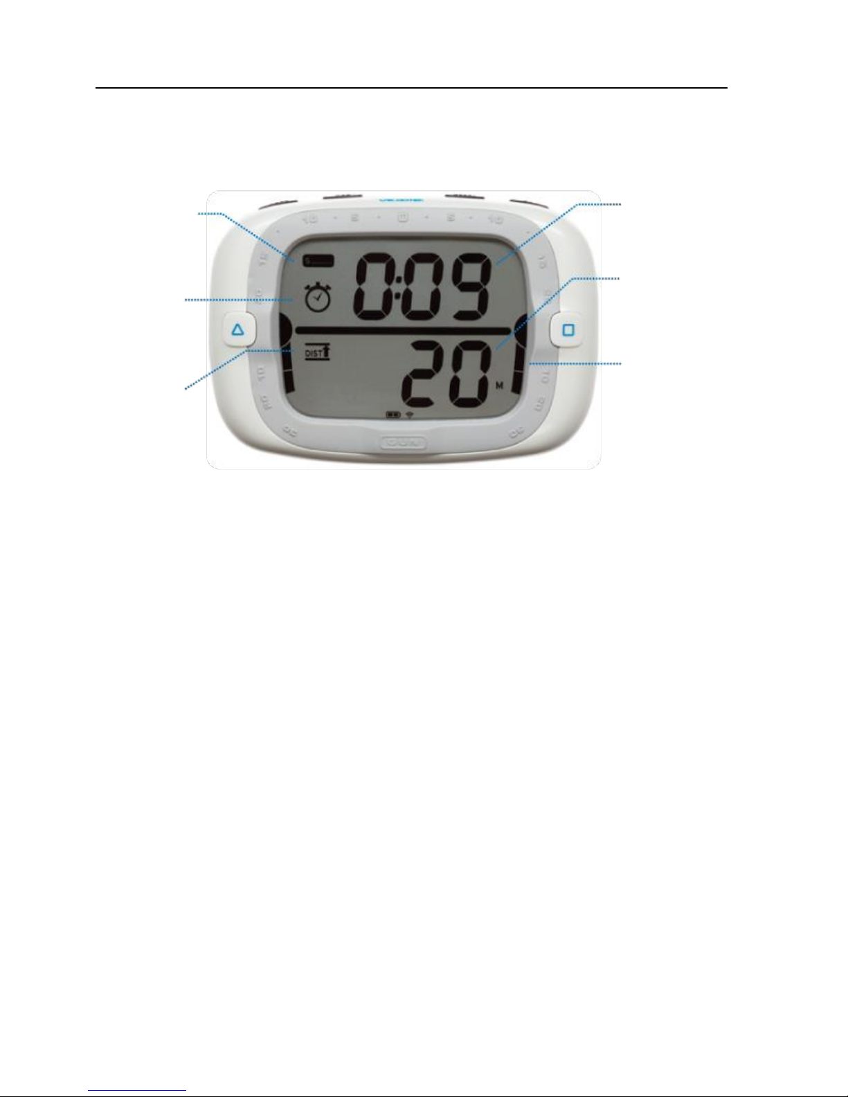
The start mode combines a timer and distance to line display to provide the information necessary for a
perfect start at the gun.
The semi-circles next to the PIN and RC buttons indicate if the respective ends are set. When both ends
are set a line appears between them to illustrate that the line is set.
Timer
The count-down timer displayed as mm:ss. The time can be set from 1:00 to 15:00.
Distance-to-line
Distance-to-line is the perpendicular distance to the user defined line. Refer to Set the Start Line on
how to set the start line. Distance-to-line is displayed in meters. A negative distance-to-line means
that the boat is over the line. Three hyphens ‘---’ are displayed when the line is not defined and a GPS
signal is available. When the distance-to-line is larger than 100 meters ‘>99’ is displayed.
Distance-to-line Bar Graph
The distance-to-line bar graph provides a graphical representation for distance-to-line so you know
where you are relative to the line at a glance. The bar graph extends above and below the illustrated
line with each bar segment representing 10 meters.
Timer
Distance
Start Mode
Indicator
Distanceto-line
Display
Indicator
Timer
Display
Indicator
Distance-to
-line Bar
Graph
Page 11
Modes 10
Race Mode
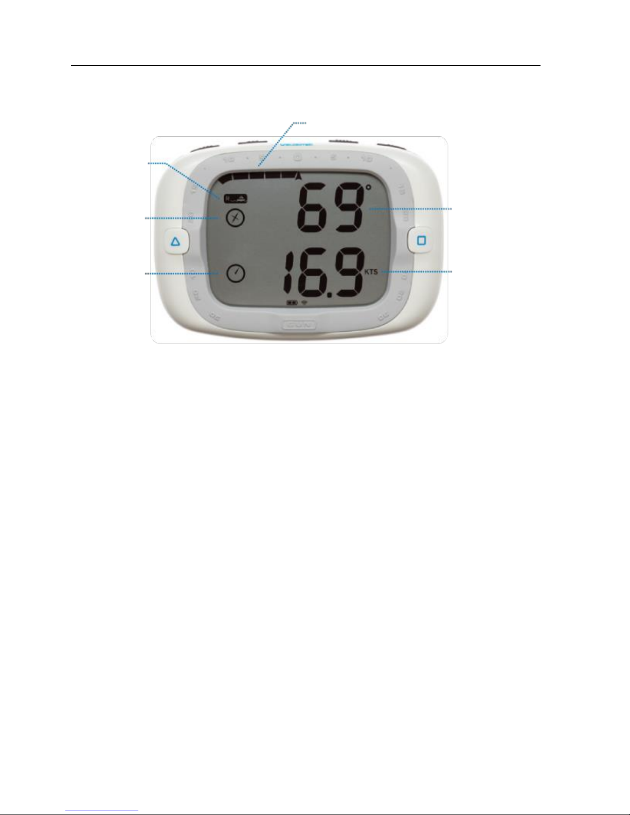
The race mode displays information crucial during the race, speed, heading and header/lift to the sailor.
Speed
Speed is calculated by the GPS unit by measuring the Doppler shift in GPS signals. It is displayed in
knots.
Heading
Heading (Course Over Ground) is calculated by the GPS unit by measuring the Doppler shift in GPS
signals.
Either true or magnetic heading can be displayed in compass mode by configuring the magnetic
declination on the ProStart. True heading is referenced to true north. Magnetic heading is referenced
to the local magnetic north. When using a magnetic compass in conjunction with the ProStart, the
magnetic heading is useful since both measurements will be referenced to magnetic north. By default
the compass displays true heading. To display magnetic heading the local magnetic declination must be
defined in device settings.
The ProStart displays heading only when your speed is greater than 1 knot, otherwise it will show a
heading of 0 degrees regardless of which direction you are actually moving.
Unlike a conventional magnetic compass, ProStart's compass reading depends on the direction you are
moving, not the direction the device is pointing. A major benefit of the ProStart over a conventional
Header/Lift each segment is 2.5 degrees
Heading
Speed
Race Mode
Indicator
Speed
Display
Indicator
Heading
Display
Indicator
Page 12

Modes 11
magnetic compass is that it will give you accurate heading information, regardless of the orientation in
which it is mounted on your boat.
Lift/Header Bar Graph
The ProStart automatically detects when a sailor is trimmed to a heading then provides the header/lift
wind shift relative to the trim angle. Once a tack or a jibe is detected the indicator resets and nothing is
indicated until another trim angle is set. Automatic detection of the trim angle normally takes 20
seconds of sailing trimmed. Each bar segment represents 2.5 degrees of wind shift.
Page 13

Configuration 12
Configuration
Compass declination is the only user configurable setting on the ProStart. Bow offset has been
removed from this version. Instructions for configure the compass declination are on page 18.
Descriptions of this setting follow.
Compass Declination
When defined to the local declination, the heading will be referenced to local magnetic north. Positive
declination represents east and negative declination represents west. To reference the compass
measurement to true north, input 0 for compass declination. Default compass declination is 0 degrees.
When using a magnetic compass in conjunction with the ProStart, setting the compass declination to the
local declination is useful since both instruments will be referenced to magnetic north.
Bow Offset
This feature has been removed.
GPS Data Storage
The ProStart records GPS data whenever the device is on and GPS signal is detected. The device
records data every 2 seconds. The ProStart can store up to 30 hours of data.
Page 14
Understanding Distance to Start Line 13
Understanding Distance to Start Line
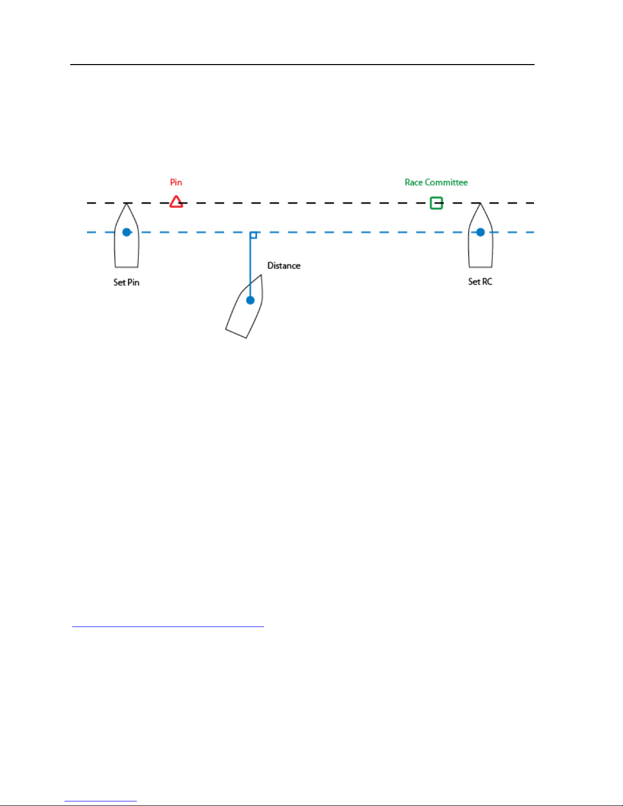
The above illustration provides a graphical definition of distance to start line and how you can set it.
Setting Ends
The start line ends can be set anywhere along the start line. We recommend sighting both the pin and
the race committee ends from outside the line. Another method is to get close to the ends just inside
the line and set them. The ends can be set at any time and in any order.
Bow Offset Calculation
This feature has been removed.
Animated Demonstration
For an animated demonstration of how to set the start line go to
http://www.velocitek.com/prostart-demo
ProStart
Page 15
Operation 14
Operation
Acquire a GPS Signal
The operation of the ProStart relies on low-power radio signals from GPS satellites that orbit the earth at
an altitude of approximately 20,000 km. As a result, the ProStart must be outdoors with a clear view of
the sky to function properly. Stay away from tall buildings and forests when acquiring a signal off the
water since these obstacles block or reflect the signals making it difficult to obtain signal.
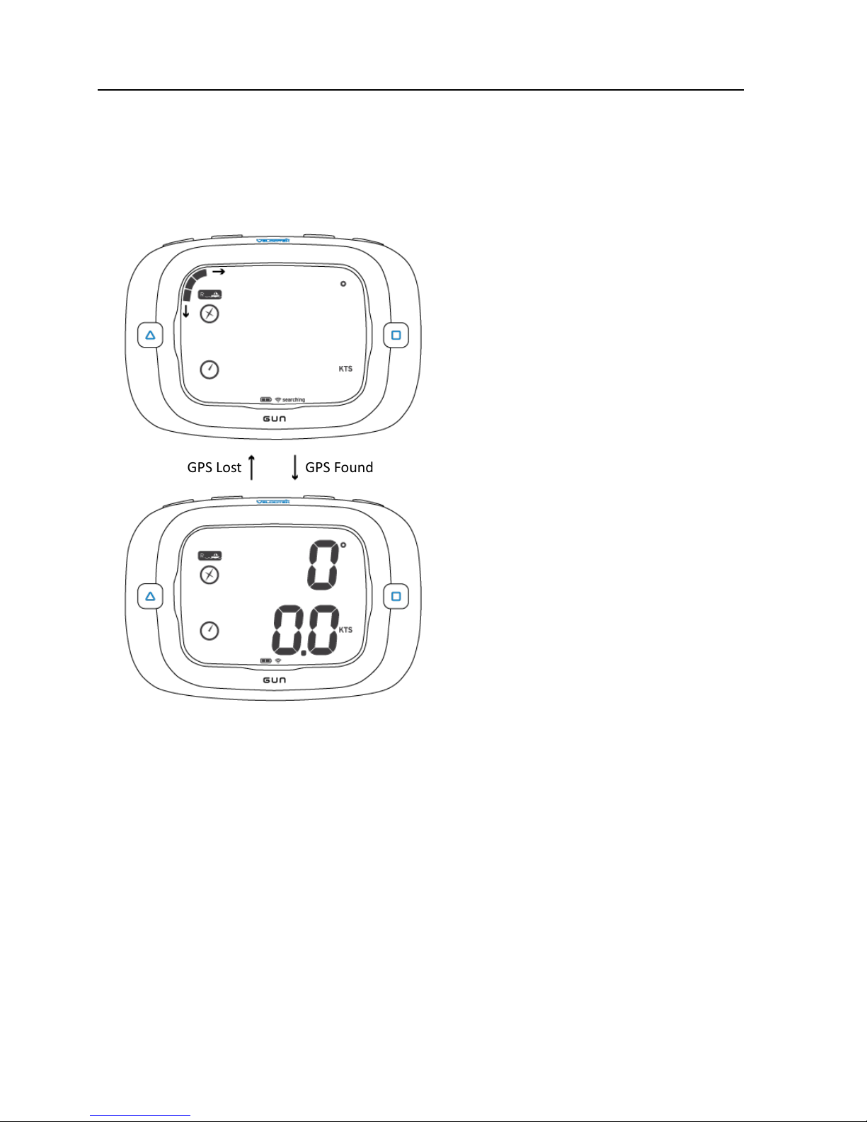
When the ProStart is first turned on, it must download information from GPS satellites before it can
acquire a GPS signal. The data download process normally takes 1-2 minutes or up to 5 minutes if
batteries have just been replaced.
GPS Found
GPS Lost
Searching for GPS signal
Searching indicator is displayed
at the bottom and bar segments
travel around the circumference
of the LCD.
GPS Signal Acquired
Page 16
Operation 15
Show Off Your Maximum Speeds
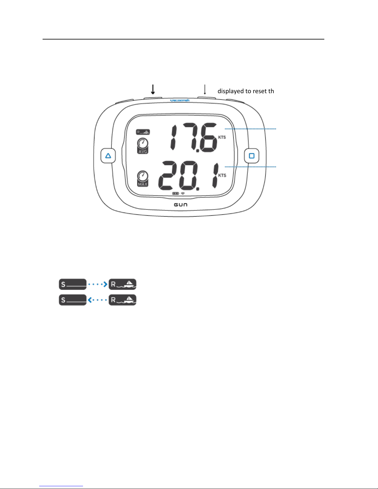
Display both your instantaneous and 10 second average maximum speed by holding MAX. To reset the
maximum speeds, press RESET while holding MAX.
Keep Your Hand on the Tiller
Modes switch automatically to minimize the need for your input. The mode switches from Start to
Race mode when the timer expires. The mode switches from Race to Start mode when any of the start
related buttons, RC, PIN, GUN, RESET and +1, are pressed.
Press RESET while max speeds are
displayed to reset the max speeds
Maximum 10
second Average
Speed
Maximum
Instantaneous
Speed
Hold MAX to display max speeds
when timer expires
when RC, PIN, GUN, RESET, +1 is pressed
Page 17
Operation 16
Set the Start Line
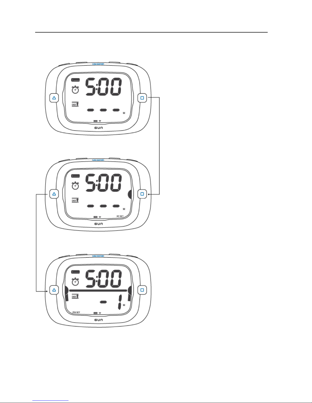
Race Committee Set
Pin Set
Race Committee End Set
Set the pin end by pressing PIN.
The set end is indicated by a semi-circle
next to RC in the illustration.
When an end is set, an indicator will flash
for 3 seconds at the bottom of the LCD at
the respective ends.
No Ends Set
Set the start line pin and race committee
ends by pressing PIN and RC respectively.
The semi-circles next to PIN and RC
indicate if the respective ends are set.
The semi-circles flash when the end is not
set and go solid when set.
The ends can be set in either order.
Start Line Set
The ends can be set again by pressing PIN
or RC.
Press both PIN and RC simultaneously to
clear the ends.
A line appears between the semi-circles
to indicate that the line is set. Distance
is displayed digitally and graphically.
Page 18
Operation 17
Use the Timer
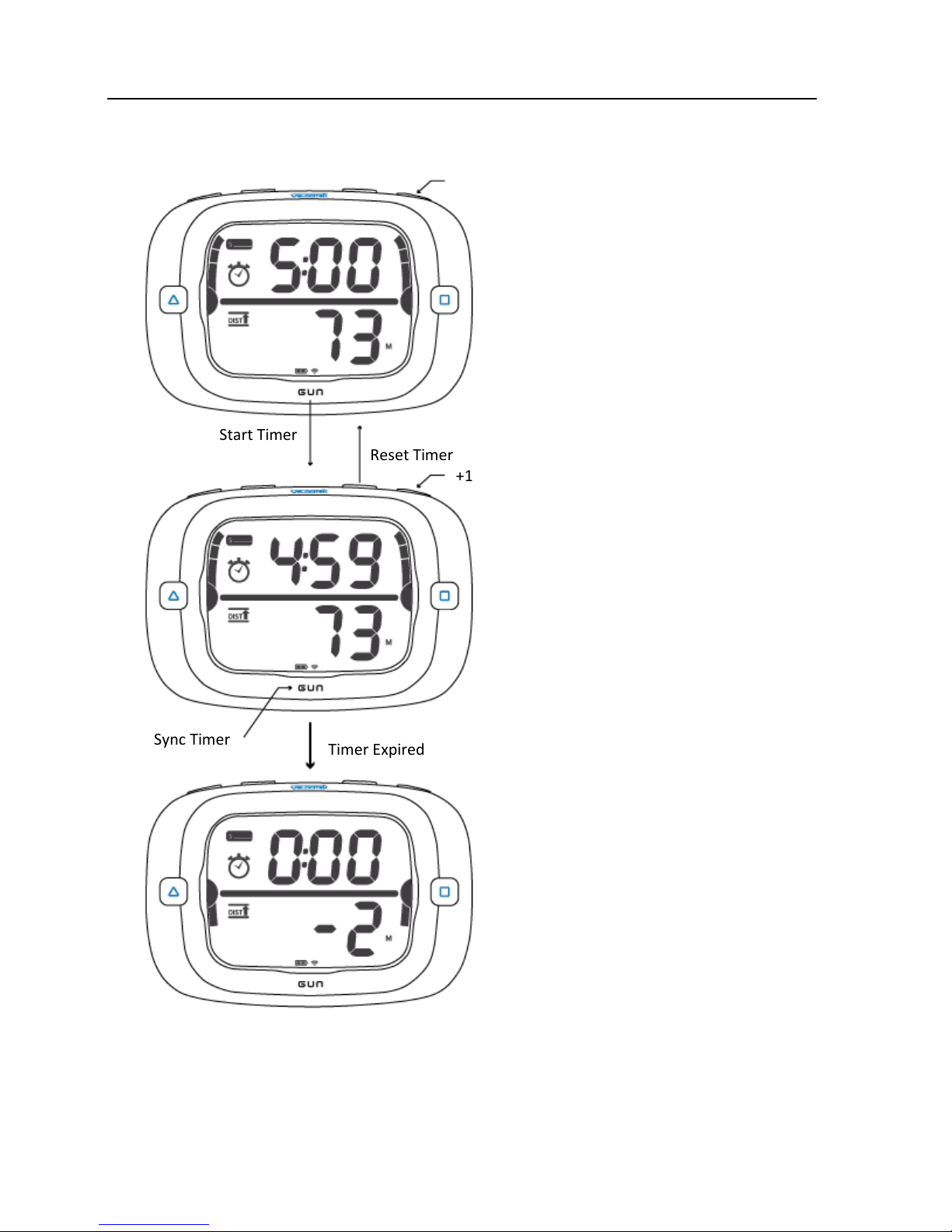
+1 min
+1 min
Sync Timer
Timer Expired
Timer Counting Down
Add one minute to the timer without
stopping the timer by pressing +1.
Reset timer by pressing RESET.
Sync timer by pressing GUN. The
timer will round down to the nearest
minutes, 4:00 in this case.
Reset Timer
Start Timer
Timer Reset
Change the reset time by pressing +1
to scroll through the minutes. The
timer can be set to 1:00 ~ 15:00.
Start the timer by pressing GUN.
Post Timer Expire
The timer will display the distance at
0:00 for 10 seconds after the timer
expires.
After the 10 seconds, the display will
switch automatically to race mode.
Page 19
Operation 18
How to Set Compass Declination
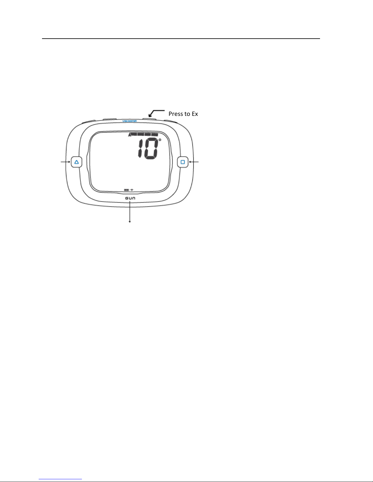
Compass declination is set by pressing and holding RESET for 3 seconds. Press GUN to confirm the
setting and exit setup menu as illustrated below.
+ 1
- 1
Hold to Enter Declination Menu
Press to Exit
Set Declination and
Exit Setup Menu
Declination Menu
Enter the declination menu by
holding RESET for 3 seconds.
Adjust declination by pressing RC and
PIN. Declination can be adjusted by
increments of 1 degree.
Set the declination and exit setup
menu by pressing GUN. Exit setup
menu without setting declination by
pressing RESET.
Page 20

Software 19
Firmware Update
Firmware is the software that runs on the ProStart. Periodically firmware updates will be available with
bug fixes and enhanced features. To update the firmware you must download either Velocitek Control
Center (for Windows) or Velocitool (for Mac) and connect your device to a computer.
Software
There are two software packages, Velocitek Control Center (for Windows) and Velocitool (for Mac),
available from Velocitek which allow you to perform GPS data download, customize device functionality
and update firmware.
Velocitek Control Center / Velocitool
Velocitek Control Center and Velocitool are free software. To find out more and download the
software, go to http://www.velocitek.com/products/controlcenter.
Page 21

Maintenance 20
Maintenance
To ensure your ProStart's enclosure remains watertight and the electronics are not destroyed by
corrosion, please take the following precautions:
Dry case with a towel before opening.
Wipe away sand or debris on the gasket before closing the back case.
Once the case is open wipe away any loose water droplets.
If you ever see signs that water is leaking inside the enclosure please contact Velocitek
immediately at (866)-498-6737 or [email protected] to arrange for your device to be
repaired and made watertight again.
Page 22

Contact 21
Contact
Mail: Velocitek, LLC
271 B Kahiko St.
Paia, HI 96779
USA
Fax: +1-650-618-2679
Phone: Calls will be answered 9AM ~ 6PM, Hawaiian Standard Time (GMT-10)
US and Canada: +1-866-498-6737
International: +1-650-592-4519
Email: [email protected]
Website: http://www.velocitek.com
Forum: http://www.velocitek.com/forums/
Support: http://www.velocitek.com/support
Page 23

Compliance 22
Compliance
FCC Compliance Statement
This device complies with Part 15 of the FCC Rules. Operation is subject to the following two conditions:
(1) This device may not cause harmful interference, and (2) this device must accept any interference
received, including interference that may cause undesired operation.
NOTE: This equipment has been tested and found to comply with the limits for a Class B digital device,
pursuant to Part 15 of the FCC Rules. These limits are designed to provide reasonable protection against
harmful interference in a residential installation. This equipment generates, uses and can radiate radio
frequency energy and, if not installed and used in accordance with the instructions, may cause harmful
interference to radio communications. However, there is no guarantee that interference will not occur in
a particular installation. If this equipment does cause harmful interference to radio or television
reception, which can be determined by turning the equipment off and on, the user is encouraged to try
to correct the interference by one or more of the following measures:
Reorient or relocate the receiving antenna
Increase the separation between the equipment and receiver
Connect the equipment into an outlet on a circuit different from that to which the receiver is
connected
Consult the dealer or an experienced radio/TV technician for help
Canadian Compliance Statement
This Class B digital apparatus complies with Canadian ICES-003.
European Community Compliance Statement
The equipment complies with The EMC Directive 2004/108/EC.
Page 24

Index 23
Index
A
Acquire a GPS Signal, 14
Animated Demonstration, 13
B
Batteries, 6
Bow Offset, 12
Bow Offset Calculation, 13
Buttons, 7
C
Compass Declination, 12
Compliance, 22
Configuration, 12
Contact, 21
Control Center, 19
Customize Your Experience, 18
D
Distance, 9
F
Firmware Update, 19
G
GPS Data Storage, 12
H
Heading, 10
I
Installation Guide, 5
L
Lift/Header Bar Graph Indicator, 11
M
Maintenance, 20
Modes, 8
O
Operation, 14
R
Race Mode, 10
S
Set the Start Line, 16
Setting Ends, 13
Show Off Your Maximum Speeds, 15
Signal Acquisition, 14
Software, 19
Speed, 10
Speed Bar Graph Indicator, 9
Start Mode, 9
T
Timer, 9
U
Understanding Distance to Start Line, 13
Use the Timer, 17
 Loading...