

Ventilation Testing
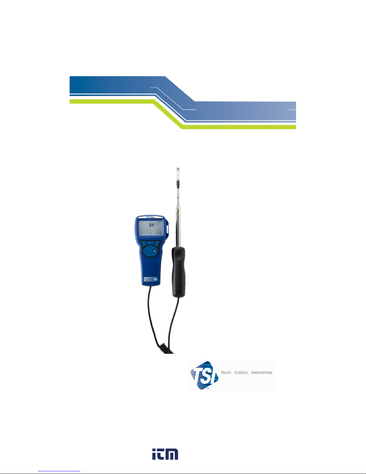
VELOCICALC®
Air Velocity Meter
Model 9515
Operation and Service Manual
ENERGY AND COMFORT
www. .com
information@itm.com1.800.561.8187

iii
CONTENTS
CHAPTER 1 UNPACKING AND PARTS IDENTIFICATION ............
1
CHAPTER 2 SETTING-UP................................................................. 3
Supplying Power to the Model 9515 VELOCICALC Air Velocity
Meter...............................................................................................
3
Installing the Batteries ............................................................... 3
Using The Telescoping Probe ........................................................ 3
Extending The Probe................................................................. 3
Retracting The Probe ................................................................3
CHAPTER 3 OPERATION .................................................................5
Keypad Functions ........................................................................... 5
CHAPTER 4 MAINTENANCE............................................................7
Recalibration...................................................................................7
Cases.............................................................................................. 7
Storage ...........................................................................................7
CHAPTER 5 TROUBLESHOOTING.................................................. 9
APPENDIX A SPECIFICATIONS..................................................... 11
www. .com
information@itm.com1.800.561.8187

3
Chapter 2
Setting-up
Supplying Power to the Model 9515 VELOCICALC Air Velocity
Meter
The Model 9515 is powered with four size AA batteries.
Installing the Batteries
Insert four AA batteries as indicated by the diagram located on the
inside of the battery compartment. The Model 9515 is designed to
operate with either alkaline or NiMH rechargeable batteries, although it
will not recharge NiMH batteries. Battery life will be shorter if NiMH
batteries are used. Carbon-zinc batteries are not recommended because
of the danger of battery acid leakage.
Using the Telescoping Probe
The telescoping probe contains the velocity and temperature sensors. When
using the probe, make sure the sensor window is fully exposed and the
orientation dimple is facing upstream.
NOTE: For temperature measurements, make sure that at least 3 inches
(7.5 cm) of the probe is in the flow to allow the temperature sensor to be in
the air stream.
Extending the Probe
To extend the probe, hold the handle in one hand while pulling on the
probe tip with the other hand. Do not hold the cable while extending the
probe as this prevents the probe from extending.
Retracting the Probe
To retract the probe, hold the handle in one hand while gently pushing
on the probe tip with the other hand. If you feel the probe antenna
binding, pull gently on the probe cable until the smallest antenna section
is retracted. Collapse the rest of the antenna by pressing the probe tip.
www. .com
information@itm.com1.800.561.8187

5
Chapter 3
Operation
Keypad Functions
ON/OFF Key
Press to turn the Model 9515 on and off. During
the power up sequence the display will show the
following: Model Number, Serial Number,
Software Revision, and Last Date Calibrated.
ft/min / m/s Key
Pressing this key changes the display to read air
velocity.
°C / °F Key
Pressing this key changes the display to read
temperature.
Changing Units
To change units, first put the desired measurement
(air velocity or temperature) on the display. Then
press and hold the left, unlabelled key for five
seconds. Finally, use the
ST and ENTER key to
select the units.
www. .com
information@itm.com1.800.561.8187

9
Chapter 5
Troubleshooting
Table 5-1 lists the symptoms, possible causes, and recommended solutions
for common problems encountered with the Model 9515. If your symptom is
not listed, or if none of the solutions solves your problem, please contact
TSI.
Table 5-1: Troubleshooting the V
ELOCICALC Model 9515
Symptom Possible Causes Corrective Action
No Display Unit not turned on Switch unit on.
Low or dead batteries Replace batteries.
Dirty battery contacts Clean the battery
contacts.
Velocity reading
fluctuates unstable
Fluctuating flow Reposition probe in
less-turbulent flow
Instrument Error
message appears
Fault in instrument Factory service required
on instrument.
WARNING!
Remove the probe from excessive temperature immediately:
excessive heat can damage the sensor. Operating temperature limits
can be found in Appendix A, Specifications.
www. .com
information@itm.com1.800.561.8187

11
Appendix A
Specifications
Specifications are subject to change without notice.
Velocity:
Range: 0 to 4000 ft/min (0 to 20 m/s)
Accuracy
1&2
: ±5% of reading or ±5 ft/min (±0.025 m/s),
whichever is greater
Resolution: 1 ft/min (0.01 m/s)
Temperature:
Range: 0 to 200°F (-18 to 93°C)
Accuracy
3
: ±0.5°F (±0.3°C)
Resolution: 0.1°F (0.1°C)
Instrument Temperature Range:
Operating (Electronics): 40 to 113°F (5 to 45°C)
Operating (Probe): 0 to 200°F (-18 to 93°C)
Storage: -4 to 140°F (-20 to 60°C)
Instrument Operating Conditions:
Altitude up to 4000 meters
Relative humidity up to 80% RH, non-condensing
Pollution degree 1 in accordance with IEC 664
Transient over voltage category II
External Meter Dimensions:
3.3 in. × 7.0 in. × 1.8 in. (8.4 cm × 17.8 cm × 4.4 cm)
Meter Weight:
Weight with batteries: 0.6 lbs (0.27 kg)
Power Requirements:
Four AA-size batteries (included)
1
Temperature compensated over an air temperature range of 40 to 150°F (5 to 65°C).
2
The accuracy statement of ±5.0% of reading or ±5 ft/min (±0.025 m/s), whichever is greater,
begins at 30 ft/min through 4000 ft/min (0.15 m/s through 20 m/s).
3
Accuracy with instrument case at 77°F (25°C), add uncertainty of 0.05°F/°F (0.03°C/°C) for
change in instrument temperature.
www. .com
information@itm.com1.800.561.8187
 Loading...