

Page 1
FREEWAVE CAPTAIN
TTL TRIGGER
USER MANUAL
Page 2

TABLE OF CONTENTS
Introduction ............................................................3
Features ....................................................................4
Compatible devices ...............................................5
Precautions ..........................................................6-7
Box contents .......................................................8-9
Overview ........................................................ 10-11
Installing the batteries &
turning on the device ......................................... 12
Setting the channels............................................ 13
Mounting the transmitter .................................. 14
Connecting to a studio flash ............................ 16
Flash trigger functions ........................................ 17
Canon-specific functions ............................. 18-19
Nikon-specific functions .............................. 20-21
Triggering the flash ............................................. 22
Using as a remote shutter release ..................23
Triggering the camera .................................. 24-27
Compatibility / USB upgrades / FCC .............. 28
Specifications ........................................................ 29
Troubleshooting .................................................. 30
Mounting the receiver ........................................ 15
2
Warranty ............................................................... 31
Page 3

THANK YOU FOR CHOOSING VELLO.
The Vello FreeWave Captain wireless triggering
system is a multi-purpose 2.4 GHz 4-channel
digital radio TTL system that empowers users
to remotely trigger flash and camera devices.
You can enjoy the freedom of triggering from
a distance up to 300 feet (100 meters).
The Vello FreeWave Captain is designed to
give photographers an easy-to-use, high-quality
TTL radio slave system. With the use of built-in
TTL functionality, your camera and flash unit
can automatically adjust your settings for the
ideal exposure in various lighting scenarios.
The wireless control capability eliminates
the presence of cable clutter, making it ideal
for studio or outdoor flash scenarios.
Remote camera triggering is another ability
of the Vello FreeWave Captain. This is helpful
when a subject, such as wildlife, may be
dicult to approach. Additionally, the wireless
function of the device removes the potential
of camera shake, making it ideal for macro,
close-up, and long-exposure photography.
The Vello FreeWave Captain’s high-speed sync
and second-curtain sync functions create easyto-control lighting eects, making it simple to
take creative and artistic images. The wireless
system has a high-speed sync of up to 1/8000
second, allowing the user to capture images
wirelessly in most shooting scenarios. Its
small size and included pouch make the Vello
FreeWave Captain simple to store and transport.
To fully understand and best use the
functions and capabilities of your Vello
FreeWave Captain, please take a moment
to read through this user guide.
3
Page 4

FEATURES
TTL functionality for Nikon ( VCTTL-N)
or Canon (VCTTL- C) units: Designed
to work seamlessly with your camera’s
i-TTL or E-TTL system.
Adjustable TTL:
Fine-tune your TTL settings.
Second-curtain sync: Allows you to
create special effects and “after blur”
images.
Wake up: Remotely wake up your ash unit
(with compatible ashes).
4 separate radio channels: Digitally coded
2.4 GHz signal, perfect for operating
multiple devices wirelessly without having
to worry about radio or ash interference.
Multiple trigger options: Wireless hot shoe,
studio ash, and shutter release triggering.
High-speed sync: Offers a maximum sync
speed of up to 1/8000 second, allowing
the user to capture images wirelessly in
most shooting scenarios.
4
Battery level indicator: Level of battery
po wer.
Backlit LCD panel: Allow viewing /
changing settings in low light.
Key lock: Ability to lock the settings against
inadvertent changes.
Sleep mode: After 10 minutes of inactivity.
Page 5
COMPATIBLE DEVICES
The Vello FreeWave Captain receiver
is available in models for both Nikon
i-TTL and Canon E-TTL cameras. The
Nikon and Canon models are each
compatible with the respective company’s
TTL (through-the-lens) technology.
To make full use of the FreeWave
Captain system, we recommend using
TTL-capable hot-shoe speedlights
from your cameras manufacturer.
5
Page 6

PRECAUTIONS
• Please read and follow these instructions
and keep this manual in a safe place.
• There are no user-serviceable parts
inside the devices. Do not attempt to
disassemble or perform any unauthorized
modification.
• Do not operate the transmitter or
receiver in the presence of flammable gas
or vapors.
• Do not handle with wet hands or immerse
in or expose to water or rain. Failure to
observe this precaution could result in fire
or electric shock.
6
• Keep out of reach of children. This device
contains small parts which may pose a
choking hazard.
• Observe caution when handling batteries.
Batteries may leak or explode if improperly
handled. Use only the batteries listed in
this manual. Make certain to align the
battery with the correct polarity.
• Batteries are prone to leakage when
fully discharged. To avoid damage to the
product, be sure to remove the batteries
when leaving the product unattended for
prolonged periods or when no charge
remains.
Page 7

• Handle the units with care.
• Do not use or leave the devices in
conditions of extreme heat, severe cold, or
high humidity.
• Turn o the power of the camera and
studio flash before inserting or removing
the remote.
• Dispose of used batteries, packaging, and
old devices in accordance with appropriate
local environmental regulations.
• Clean the unit with a soft, dry cloth.
• Make sure the item is intact and that there
are no missing parts.
• All photos are for illustrative purposes
only.
7
Page 8

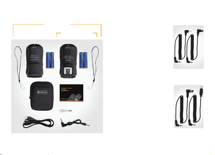
BOX CONTENTS
Transmitter and Receiver Set
(VCTTL-C and VCTTL-N)
• Transmitter
• Receiver
• 4× AA batteries
• 3.5 mm to 3.5 mm studio flash cable
• 3.5 mm to 1/4″ monoplug adapter
• Shutter release cables (see page 9)
• USB upgrade cable
• 2× lanyards
• Pouch case
• User manual
8
Receiver Only
(VCTTL-CR and VCTTL-NR)
• Receiver
• 2× AA batteries
• 3.5 mm to 3.5 mm studio flash cable
• 3.5 mm to 1/4″ monoplug adapter
• 1× lanyard
• User manual
Page 9
VCTTL-C/N
VCTTL-CR/NR
Also Included with Canon Set (VCTTL-C)
• Shutter Remote 2.5 mm
to Canon 2.5 mm Shutter
Release Cable (RCC-C1)
• Shutter Remote 2.5 mm
to Canon 3-Pin Camera
Shutter Release Cable
(RCC-C2)
Also Included With Nikon Set (VCTTL-N)
• Shutter Remote 2.5 mm to
Nikon 10-Pin Camera Shutter
Release Cable (RCC-N1)
• Shutter Remote 2.5 mm to
Nikon DC2 Camera Shutter
Release Cable (RCC-N2)
• Shutter Remote 2.5 mm to
Nikon D70s/D80 Camera Shutter
Release Cable (RCC-N3) (Not Shown)
9
Page 10
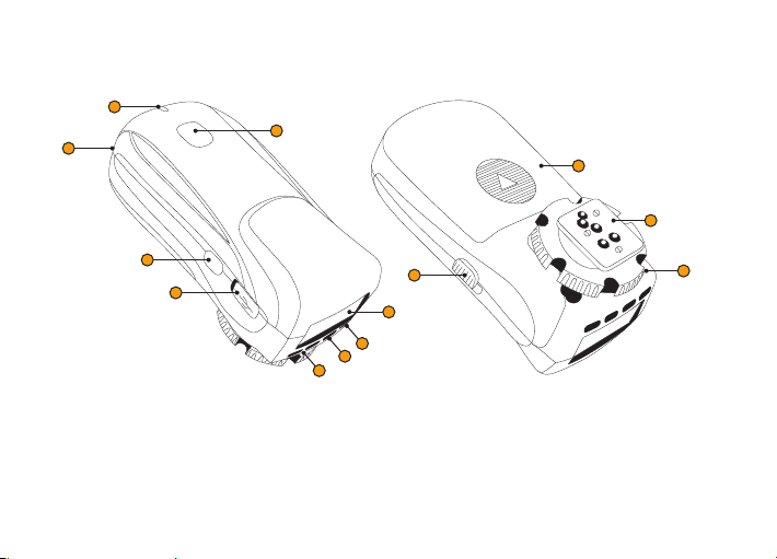
OVERVIEW Transmitter
2
1
3
11
12
4
5
7
6
1. Shutter release test button
2. LED indicator
3. Lanyard loop
4. Flash test button
5. Mini-USB port
10
6. EV compensation buttons
7. Channel selector button
8. Function button
9. LCD screen
10. On/o switch
10
9
8
11. Battery compartment door
12. Hot-shoe foot
13. Tightening screw
13
Page 11

Receiver
2
3
4
5
6
1
12
13
10
11
9
8
7
14
15
1. Shutter release test button
2. LED indicator
3. Lanyard loop
4. Channel selector switch
5. Flash test button
6. Mini-USB port
7. 3.5 mm flash-trigger output
8. 2.5 mm shutter-release output
9. DC5V power port
10. Hot-shoe mount
11. On/o switch
12. Battery compartment door
13. Cold-shoe foot
14. 1/4″-20 light-stand thread
15. Tightening screw
11
Page 12

INSTALLING THE BATTERIES & TURNING ON THE DEVICE
The Vello FreeWave Captain transmitter
and receiver each take two AA batteries.
To install the batteries, simply remove the
battery compartment door on the back of
the unit. With the door removed, insert the
batteries with the correct polarity as displayed
within the compartment. Once secured,
reinstall the battery compartment door.
To turn on the Vello FreeWave Captain
transmitter or receiver, simply slide the on/
o switch to the ‘on’ position. Reverse
this step to turn the device o.
12
Page 13

SETTING THE CHANNELS
The Vello FreeWave Captain transmitter
and receiver can communicate with your
choice of four separate channels, thereby
allowing the photographer to shoot without
interference from other shooters.
To change the channel on the transmitter,
turn on the device and press the channel
selector [ ] button until the desired
channel appears on the LCD screen.
To change the channel on the receiver,
use the channel selector switch
on the left side of the unit.
The channels on both the transmitter
and receiver must be synchronized for
the two devices to communicate.
13
Page 14

MOUNTING THE TRANSMITTER
To wirelessly trigger your flash device using the
Vello FreeWave Captain, the transmitter must
be mounted on the camera’s hot shoe. With
both devices turned o, slide the transmitter’s
hot-shoe foot into the camera’s hot-shoe
mount. Turn the transmitter’s tightening
ring to secure the device to the camera.
14
Page 15

MOUNTING THE RECEIVER
Note: Make sure your flash and FreeWave
Captain are turned o before mounting.
Mount the receiver to your tripod or stand via
one of the two provided mounting options:
1. Threaded socket for a standard 1/4″ screw
mount.
2. Accessory shoe (cold shoe) foot.
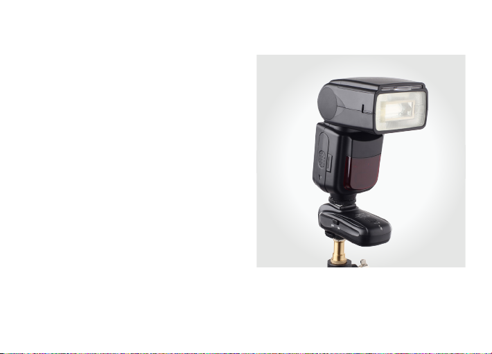
Mounting a Hot-Shoe Flash
To mount your hot-shoe flash to the
receiver, slide the foot of the hot-shoe
flash into the receiver’s hot-shoe mount.
Secure the flash to the hot-shoe mount.
15
Page 16

CONNECTING TO A STUDIO FLASH
With all devices turned o, plug the 3.5 mm
studio flash cable into the receiver’s flash [ ]
port. Plug the other end into your studio flash.
If your flash does not accept a 3.5 mm cable,
attach the 1/4″ monoplug adapter to the cable
and insert that into the studio flash’s input.
Note: For studio flashes with household plugs,
a 3.5 mm to household adapter is available
separately.
16
Page 17

FLASH TRIGGER FUNCTIONS
TTL EV Control
The Vello FreeWave Captain’s transmitter
provides the user with the ability to manually
adjust the TTL reading of a TTL-capable
flash. This function can adjust the TTL
reading in 1/3 stops between -3 and +3. To
use this function, simply push the + or - EV
buttons on the bottom of the transmitter.
Tip: Each photographer has their own vision
of proper image exposure. The EV settings
allow the photographer to adjust the TTL
exposure to reflect their own specific vision.
Note: Remote flash units attached the Vello
FreeWave Captain receiver need to be set to
TTL EV 0 for proper TTL exposure control
by the Vello FreeWave Captain transmitter.
Separate EV adjustments to individual remote
flashes will result in improper TTL exposure.
Note: The Vello FreeWave Captain is optimized for
Nikon and Canon TTL flashes. Not all third-party
flashes may be compatible.
Camera-Specific Information
For more information about your specific camera
visit our page here:
www.vellogear.com/Camera_Specific_Compatibilities/
17
Page 18

CANON-SPECIFIC FUNCTIONS
High-Speed Sync (HSS) Control
High-speed sync (HSS) allows your camera
to set the shutter speed faster than what
flash would normally be able to fire in sync
with. HSS mode instructs the flash to fire
multiple short pulses of light to match the
shutter’s speed. To the camera, this will
appear as one continuous flash. Because of
the short duration of the light, the flash needs
to be positioned closer to the subject.
To activate high-speed sync mode, set your
transmitter to HSS mode by pushing the
function [ ] button until HSS appears on
the Vello FreeWave Captain’s LCD display.
18
Second-Curtain Sync (SCS) Control
Second-curtain sync (SCS) fires a flash at
the end of an exposure (rather than at the
beginning) to create the illusion of motion
in an image. This creates an image that
blurs the motion of the subject from its
position at the beginning of the exposure
and then fully illuminates and captures its
position at the end of the exposure.
To activate, set your transmitter to SCS
mode by pressing the function [
button until SCS appears on the Vello
FreeWave Captain’s LCD display.
Note: Canon wireless flash functions
need to be disabled in your cameras
menu setting to use SCS.
Page 19

AF Illumination Control
On a Canon camera, the AF illumination
light is controlled by adjusting the settings
within your camera body. See your Canon
instruction manual for your camera model.
Wake Up
To remotely wake up a flash unit, halfpress the flash test [ ] button.
Key Lock
Press and hold the function [ ] button
for 2 seconds to initiate the key-lock function.
A lock icon [ ] will appear on the screen
and no setting changes can be made to the
unit while this mode is initiated. Press and
hold the function [ ] button for 2
seconds to disable the key-lock function.
Canon M2 Mode
The M2 Mode is for select Canon models
that use a newer sync protocol. If your
Canon camera does not work in the default
mode, then switch the transmitter to
the M2 mode to see if it's compatible.
Press and hold the EV + and Function
[ ] button together to enter M2 mode.
The transmitter will default to High Speed
Sync and appear on the LCD as HSS M2.
To exit HSS and enter M2 mode, press
the Function button [ ] again.
Press and hold the EV + and Function
[ ] buttons together to disable M2 mode.
Note: In M2 mode, second-curtain sync is not supported.
19
Page 20

NIKON-SPECIFIC FUNCTIONS
High-Speed Sync (HSS) Control
High-speed sync (HSS) allows your camera
to set the shutter speed faster than a flash
would normally be able to fire in sync with.
HSS mode instructs the flash to fire multiple
short pulses of light to match the shutter’s
speed. To the camera, this will appear as
one continuous flash. Because of the short
duration of the light, the flash needs to
be positioned closer to the subject.
To activate high-speed sync mode
on Nikon cameras, set your camera
to a shutter speed above 1/250.
20
Second-Curtain Sync (SCS) Control
Second-curtain sync (SCS) fires a flash at
the end of an exposure (rather than at the
beginning) to create the illusion of motion
in an image. This creates an image that
blurs the motion of the subject from its
position at the beginning of the exposure
and then fully illuminates and captures its
position at the end of the exposure.
To set your Nikon camera to SCS
mode, follow the instructions
in your camera’s manual.
Page 21

AF Illumination Control
Wake Up
To be able to control AF illumination with
the Vello FreeWave Captain, turn o AF
illumination in your camera according to
the instructions in your camera’s manual.
The AF illumination light emitted by the
Nikon Flash can be controlled via the
transmitter’s AF function. To turn o this
function, push the function [ ] button.
With your camera's AF illumination set to OFF,
the Vello FreeWave Captain will allow you to
turn the AF illumination of your flash on or
o without going through the camera menu.
To remotely wake up a flash unit, halfpress the flash test [ ] button.
Key Lock
Press and hold the function [ ] button
for 2 seconds to initiate the key-lock function.
A lock icon [ ] will appear on the screen
and no setting changes can be made to the
unit while this mode is initiated. Press and
hold the function [ ] button for 2
seconds to disable the key-lock function.
21
Page 22

TRIGGERING THE FLASH
1. With all devices turned o, connect
and secure the transmitter to
the camera by securing it to your
camera’s hot-shoe mount.
2. Mount and secure the receiver
to your remote flash unit.
3. Turn on the camera, flash,
transmitter, and receiver.
4. Synchronize the channel selection
on the transmitter and receiver.
5. Press the flash test [ ]
button on the transmitter or
receiver to verify flash firing.
22
6. With your camera set to the desired mode
and settings, half-press the shutter release
on the camera to autofocus the camera.
7. Fully press the shutter release on the
camera to activate the camera’s shutter
and flash simultaneously. A green light
will appear on the transmitter when the
signal is sent, and a red light will appear on
the receiver when the signal is received.
Page 23

USING AS A REMOTE SHUTTER RELEASE
Mounting the Receiver On-Camera
To mount the receiver to your camera,
slide the device into the camera’s hotshoe mount. Turn the receiver's tightening
ring to secure it to the camera.
Connecting the Receiver to Your
Camera
Note: To use the FreeWave
A wired connection is required to connect
the receiver to your camera. With all of
the devices o, connect the shutter release
cable to your receiver by inserting the
2.5 mm end into the receiver’s shutter
release [ ] port. Insert the other end
into the camera’s shutter release port.
Captain in remote shutter
release function with a
flash, mount your receiver
onto a bracket or light
stand. Connect the receiver
to the camera via the
shutter release cable and
mount your flash onto
your camera's hot shoe.
23
Page 24

TRIGGERING THE CAMERA | SINGLE-SHOT MODE
1. With all devices turned o, connect
and secure the receiver to the camera
by plugging the 2.5 mm shutter release
cable into the camera’s shutter remote
port and the other end into the
receiver’s shutter release [ ] output.
2. Turn on the camera,
transmitter, and receiver.
3. Synchronize the channel selection
on the transmitter and receiver.
4. Set your camera to single-shot mode.
5. Half-press the shutter release test
[ ] button on the transmitter
to autofocus the camera.
24
6. Fully press the shutter release test [ ]
button on the transmitter to activate
the camera’s shutter. A green light will
appear on the transmitter when the signal
is sent, and a red light will appear on the
receiver when the signal is received.
Page 25

TRIGGERING THE CAMERA | CONTINUOUS-SHOT MODE
1. With all devices turned o, connect and
secure the receiver to the camera by
plugging the 2.5 mm shutter release cable
into the camera’s shutter remote port and
the other end into the receiver’s shutter
release [ ] output.
2. Turn on the camera, transmitter, and
receiver.
3. Synchronize the channel selection on the
transmitter and receiver.
4. Set your camera
to continuous
shot mode.
5. Half-press the shutter release test
[ ] button on the transmitter to
autofocus the camera.
6. Fully press and hold the shutter release
test [ ] button on the transmitter
to activate the camera’s shutter. Release
the button to stop the shutter. A green
light will appear on the transmitter when
the signal is sent, and a red light will
appear on the receiver when the signal
is received.
25
Page 26

TRIGGERING THE CAMERA | BULB MODE
1. With all devices turned o, connect
and secure the receiver to the camera
by plugging the 2.5 mm shutter release
cable into the camera’s shutter remote
port and the other end into the
receiver’s shutter release [ ] output.
2. Turn on the camera,
transmitter, and receiver.
3. Synchronize the channel selection
on the transmitter and receiver.
4. Set your camera to bulb mode.
5. Half-press the shutter release test
[ ] button on the transmitter
to autofocus the camera.
26
6. Fully press and hold the shutter release
test [ ] button on the transmitter to
open the camera’s shutter. A green light
will appear on the transmitter when the
signal is sent, and a red light will appear on
the receiver when the signal is received.
7. Release the button to close the shutter.
Page 27

TRIGGERING THE CAMERA | SELF-TIMER MODE
1. With all devices turned o, connect
and secure the receiver to the camera
by plugging the 2.5 mm shutter release
cable into the camera’s shutter remote
port and the other
receiver’s shutter release
2. Turn on the camera,
transmitter, and receiver.
3. With your camera’s shutter speed
set to higher speed than bulb, set
your camera to self-timer mode.
4. Synchronize the channel selection
on the transmitter and receiver.
end into the
[ ]
output.
5. Half-press the shutter release test
[ ]
button on the transmitter
to auto-focus the camera.
6. Fully press the shutter release test [ ]
button on the transmitter to activate the
shutter in self-timer mode. A green light
will appear on the transmitter when the
signal is sent, and a red light will appear on
the receiver when the signal is received.
NOTE: When used as a remote shutter release,
the Vello FreeWave Captain will not fire a
separately mounted remote flash in sync with the
camera, even when they are on the same channel.
27
Page 28

COMPATIBILITY
The Vello FreeWave Captain shares a radio signal frequency with the Vello
Flash Trigger LR on the first four channels. Pairing these units is ideal for
those looking for an economic option to expand their lighting setups.
USB UPGRADES
Updates for the Vello FreeWave Captain will be available on the Vello website, at
www.vellogear.com.
and connect the transmitter and receiver to it using the included USB to mini-USB cable.
To update your devices, download the update to your computer
FCC COMPLIANCE
This device complies with Part 15 of the FCC Rules. Operation is subject to the following
two conditions: (1) this device may not cause harmful interference, and (2) this device must
accept any interference received, including interference that may cause undesired operation.
28
Page 29

SPECIFICATIONS
Transmitter
Frequency 2.4 GHz 2.4 GHz
Channels 4 channels 4 channels
Operating Range
Sync Speed 1/8000 maximum 1/8000 maximum
Connections Hot-shoe foot, USB port Hot-shoe mount, USB port,
Power Source
Dimensions
Weight (with batteries) 4.7 oz. (134 g) 4.7 oz. (133 g)
Up to 300′ (100 m) Up to 300′ (100 m)
5 V DC power input, USB Port
2× AA batteries 2× AA batteries or
3.63″ × 1.87″ × 1.72″
(9.21 × 4.75 × 4.37 cm)
Receiver
3.5 mm flash sync port,
2.5 mm shutter release port,
optional AC adapter
3.66″ × 1.85″ × 1.8″
(9.3 × 4.71 × 4.56 cm)
29
Page 30

TROUBLESHOOTING
Check that channels on all communicating
devices are identical. When turning on
the unit, it is important to review and, if
necessary, reset the group selection.
If first choice of channel does not work, try
a dierent channel until you find one that
works.
Ensure that all cables are installed correctly.
Make sure that the power source for each
device is properly installed and carrying a
sucient charge. Weak batteries can reduce
the distance over which a transmission works.
If you are triggering with a wired connection,
make sure the device is connected using the
correct cable and make sure the cable is
connected to the correct input or output.
30
Make sure that a communication confirmation
appears on the LCD screen when sending a
signal.
Verify that flash and camera equipment are
operating properly.
Check for a stuck Test button on all units,
including flash devices.
Make sure the devices are within the
maximum operating distance of 300 feet
(100 meters).
Page 31

ONE-YEAR LIMITED WARRANTY
This Vello product is warranted to the original purchaser to be free from defects in materials and workmanship
under normal consumer use for a period of one (1) year from the original purchase date or thirty (30) days
after replacement, whichever occurs later. The warranty provider’s responsibility with respect to this limited
warranty shall be limited solely to repair or replacement, at the provider’s discretion, of any product that fails
during normal use of this product in its intended manner and in its intended environment. Inoperability of
the product or part(s) shall be determined by the warranty provider. If the product has been discontinued,
the warranty provider reserves the right to replace it with a model of equivalent quality and function.
This warranty does not cover damage or defect caused by misuse, neglect, accident, alteration, abuse, improper
installation or maintenance. EXCEPT AS PROVIDED HEREIN, THE WARRANTY PROVIDER MAKES NEITHER
ANY EXPRESS WARRANTIES NOR ANY IMPLIED WARRANTIES, INCLUDING BUT NOT LIMITED TO ANY
IMPLIED WARRANY OF MERCHANTABILITY OR FITNESS FOR A PARTICULAR PURPOSE. This warranty
provides you with specific legal rights, and you may also have additional rights that vary from state to state.
To obtain warranty coverage, contact the Vello Customer Service Department to obtain a return merchandise
authorization (“RMA”) number, and return the defective product to Vello along with the RMA number
and proof of purchase. Shipment of the defective product is at the purchaser’s own risk and expense.
For more information or to arrange service, visit www.vellogear.com or call Customer Service at 212-594-2353.
Product warranty provided by the Gradus Group.
www.gradusgroup.com
Vello is a registered trademark of the Gradus Group. © 2015 Gradus Group LLC. All Rights Reserved.
31
Page 32

www.vellogear.com
© Copyright 2015 Gradus Group
GG4
 Loading...