

Page 1
FREEWAVE
VIEWER
WIRELESS LIVE-VIEW
REMOT E
Page 2

2
INTRODUCTION
Thank you for choosing the Vello FreeWave
Viewer W ireles s Live-V iew Remote. The
Viewer d isplay s the live v iew from th e LCD
displ ay on your ca mera a nd can tr igger t he
shutter from 2 00 feet (60 mete rs) away
under optimal conditions.
The FreeWave Viewer do es not require
line- of-si ght alignment , as its radio waves
pass th rough and around o bject s such as
walls, windows, and floors.
It features two m odes to e nhance your
shooting experience. A/V mode functions
as the Li ve View on yo ur came ra would ,
allowi ng you to see what you r lens see s.
The CCT V mode a llows for a w ider- angle
view fro m the rece iver’s built-in c amera,
allowi ng you to see action o utside the field
of view of your came ra’s lens .
Suggested U ses For Your L ive-View
Remote:
Shoot ing wild life or ot her dan gerous o r
elusi ve subjec ts from a d istance.
Photo graph ing chil dren and o ther shy
subjects tha t act di erentl y when in t he
prese nce of a photogra pher.
Maintaining a view from the camera
when th e camer a is in a hard-to -access
location.
Creating live-view function in cameras
that don’t possess this feature through
use of the built- in CCT V.
Conse rving p ower on you r camer a by
turni ng o the LCD.
Page 3

KEY FEATURES
3
2.4GHz Rad io Freq uency : Provide s
improve d signal q ualit y with red uced
interference .
Long Ra nge: Ov er 200 ft in opt imal
conditions.
Multi-Purpose: Real-time monitoring of
eithe r your DSL R’s Live View o r the
Transmit ter’s bu ilt-in CC TV cam era.
Dual -Fun ction S hutt er / Auto Focus
Button: Press h alfwa y to focus; p ress
fully to r elease t he shut ter.
Clea r Viewin g: The Rec eiver fe atures a
3.5” TF T LCD scre en with a re soluti on
of 320 x 240 a nd 10 levels of b rightn ess
adjustment.
Power Opt ions: Transmit ter and Re ceiver
can be pow ered by usi ng 4 alka line,
lithiu m or Ni- MH AA b atter ies or by
connec ting to a U SB power s ource. T he
Transmit ter ca n attac h to 5V DC powe r
so you can o perat e the tra nsmitt er
indefinitely.
Control Multiple Cameras: You can set
the Rece iver to con trol any o ne of up to
four cam eras o utfit ted with Tra nsmit ters
that are s et up wit hin rang e of the
Re ce iv er.
Versatile: The Tran smitt er work s with
DSLR c amera s from many m anufa cturer s
- just use t he appro priat e Sync cab le.
With on e receive r, you can cont rol
cameras from multiple manufacturers.
Your Vello F reeWave V iewer c ontai ns:
Canon Kit Nikon Kit
Wireless
Transmitter
Wireless
Receiver
Carrying
Case
AV Cable
Release
Cable
CVC-10
CVC-20
CVC- 40
RCC-C1
RCC-C 2
CVC-20
CVC-30
RCC-N1
RCC-N 2
Page 4
4
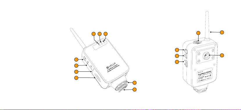
OVERVIEW OF TRANSMITTER
1. Power LED Indica tor
2. Status LED Indicator
3. Shooting LED Indicator
4. Audio Video/Microphone
Input (1/8 ” mini)
5. Rem ote Shu tter- Relea se
Output (sub-mini)
6. US B Power Inp ut
7. Battery Door
8. Shoe-Mount Locking Collar
9. ¼”-20 Threaded Rece iver
321
10. Channel Selection Switch
11. Code-Matching But ton
10
14
12. 5V DC Powe r Input
13. Power- Switch
4
5
6
7
14. Antenna
15. CCT V Camera
8
9
11
12
13
15
Page 5
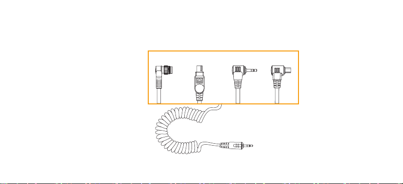
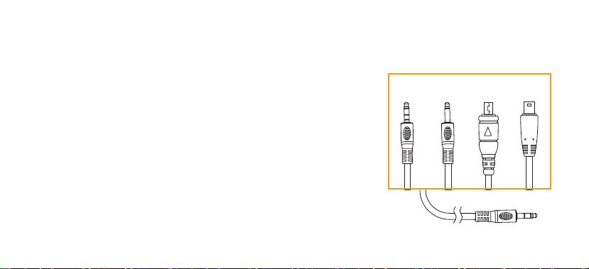
OVERVIEW OF REMOTE CAMERA CABLES
5
RCC-N1 – Nikon
10-Pin Connection
RCC-N2 – Nikon
DC2 Connection
RCC-C1 – Canon
Sub-Mini Connection
RCC-C2 – Canon
3-Pin Connection
RCC-N1
RCC-N2
RCC-C1
Transmitter Side
RCC-C2
Page 6
6
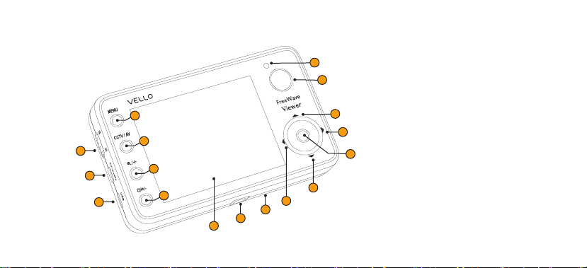
OVERVIEW OF RECEIVER
4
1
2
3
5
6
8
9
1. Power Swi tch
2. Audio Video/Audio Output
3. US B Power In put
10
11
12
7
17
15
16
13
14
4. MEN U But ton
5. CCT V (Transmitt er’s Buil t-In C amera)/
AV (Camer a’s Live View) S elect ion
Button
6. Vi deo Enla rge Button (for Tra nsmit ter’s
Buil t-In C amer a)
7. Cha nnel Swi tch/S leep Mode But ton
8. Status LED
9. Shut ter/Aut o Focus
Page 7
10. Volume U p/Nav igate U p (Whe n in
Enlarge mode)
11. Increase Screen Brightness/Navigate
Right ( When in Enlar ge mode)
12. OK B ut ton
13. Volume Down/ Navig ate Down ( When
in Enlarge mode)
14. Decrease Screen Brightness/Navigate
Left ( When i n Enlar ge mode)
15. Batter y Door (N ot pictu red/On back
of Recei ver)
16. ¼”-20 Th readed Re ceiver
17. LCD Display
OVERVIEW OF CAMERA VIDEO CABLES
CVC-10 – Canon 5D Mark I I
CVC-20 – Canon G11, G12, G1
CVC-10
X, Rebel XS, Rebel XSi, 40D,
50D
Nikon D90, D300s, D700
CVC-30 – Nikon D5100, D7000
CVC-40 – Canon Rebel T1i,
Rebel T2i, Rebel T3i, 60D, 7D,
1D Mark IV, 5D Mark III
7
CVC-20 CVC-30 CVC-40
Transmitter Side
Page 8

8
SAFETY WARNINGS
•ConrmtheFreeWaveViewerand
camer a are powe red OFF b efore
installing the device.
•E xtern alenvironmentalfrequencies
may hinder the over all per form ance
of this product , as wit h most radio
controlled devices.
•Donotforciblypullonthecables
once they’re conne cted to t he
camera.
•Thiselec tronicd eviceisN OT
water proof. E xposure to moisture
and immersion i n water c an
permanentl y damage the FreeWave
Vi ew e r.
•Prolonge dvibrationmayre sultin
product failure.
•W hentheFreeWaveVieweri s
not in use for a prolonged per iod,
remove th e batte ries from both th e
Transmit ter and t he Recei ver.
•Donotexpo setheFreeWaveViewer
to extreme temperatures, high
humidity, or direct sunlight.
•Donotusea mmablegasesw hen
operating this electronic device.
•Disposeofb atteriesinaccordance
with local environmental regulations.
Page 9

FreeWave
Viewer
AV / MIC
1 2 3 4
CHANNEL
FreeWave
Viewer
AV / MIC
1 2 3 4
CHANNEL
SETTING UP
1. S lide and o pen the b atter y door o n
the Transmitte r and inse rt 4 alk aline ,
lithium or Ni- MH A A batte ries as
speci fied by the d iagr am within the
batte ry com part ment . Close th e
batte ry doo r.
2. Slide and o pen the b atter y door o n the
Receiver and ins ert 4 al kaline , lithi um
or Ni- MH AA batte ries as s pecified
by the diagram w ithin t he batt ery
compa rtme nt. Clo se the bat ter y door.
9
Page 10

10
SETTING UP
3. Mount the Trans mitte r to your
camer a’s hot shoe , a cold sh oe or to a
¼”-20 threaded stu d on any mounting
adapt er or support de vice.
a. For shoe-mounting, loosen the locking
collar by turnin g it counterclo ckwise
and slid e the Transm itter’s foot for ward
into th e shoe. Twist the lock ing coll ar
on the Transmitt er clock wise t o tighte n
until the unit is secure.
FreeWave Viewer
Wireless Live-View Remote
b. For mou nting to a ¼”-2 0 thread ed stud
– for exa mple a tripod, s tand adapter,
access ory cl amp or ca mera br acket –
line up the male sc rew’s thre ad with
the Transmitte r’s femal e receive r and
rotat e the screw u ntil the c onnec tion is
tight.
Page 11

SETTING UP
11
4. Insert t he tran smitter side of the
Remote S hutt er Relea se Cabl e into
the transmit ter’s Sync port , and in sert
the cam era sid e of the ca ble into yo ur
DSLR c amera’s shutte r release port .
5. Inser t the tra nsmit ter sid e of the AV
cable i nto the transm itter ’s AV/Mic
port , and in sert the camer a side of t he
cable i nto the c amera’s A /V ou tput .
Note: Ens ure tha t all dev ices ar e turned off
when making co nnect ions , that ca bles ar e
seated properly and that bat tery doors ar e
securely closed.
Page 12

12
SYNCHRONIZING TRANSMITTER AND RECEIVER
1. Tu rn on the Tran smitt er by slid ing
the powe r switc h upward . When
Transmi tter power is on, t he Power
LED Ind icator shines re d.
Note: If ba tter y power for the Transmitter is
low, the Tran smit ter’s Power LED Indicat or
will ash red . This means that the bat terie s
should be replaced or re charg ed immediately.
2. Turn on the Receiver by slidi ng the
power sw itch upward. The Receiv er
will show the FreeWave V iewer
star t-up sc reen gr aphic a nd then se ek
out a sig nal.
Note: If ba tter y power for the Receiver is low,
the Rec eiver ’s Power LE D Indicator will as h
red and a n icon of a batter y will ash on t he
LCD screen. This means that the batteries
should be replaced or re charg ed immediately.
3. If no signal is fo und, “ Disconnected”
will display at th e botto m of the screen.
Make sure the Transmitte r is on and
that the Transmitter and Recei ver are
set to th e same channel – th e switc h on
the top o f the Transm itter s hould be
set to th e same num ber as the numbe r
shown at t he top le ft corn er of the
Receiver’s LCD screen.
Page 13

SYNCHRONIZING TRANSMITTER AND RECEIVER
13
4. If a signal is still not found, Sync -Code
Match ing is necessar y. Press t he Menu
butt on on the Re ceiver, and use the
Left a nd Right selection but tons to
selec t Sync. U se the Up a nd Down
selec tion buttons t o select Yes, and
press t he OK but ton. ( The Sta tus LED
Indic ator wil l glow green wh ile this Sy nc
proces s occur s.) Then pr ess and ho ld
the Cod e butto n on the Trans mitte r
for two se conds . The Sta tus LED
Indic ator wil l flash re d until th e proces s
is finished.
5. When the signal of the Tran smitt er is
found, the Recei ver LCD sc reen wil l
show the r eal-t ime view o f eithe r the
Transmitter’s camera o r the DSL R
camera’s LCD.
Page 14

14
1 2 3 4
CHANNEL
CHANNEL SELECTION
1. To est ablis h Sync between the Receiv er
and a Transmitte r, both devices must
be set to t he same channel . In the
event th at you are u sing one Re ceiver
to control and monitor mo re than on e
camer a, the Transmit ters w ill need
to be ass igned to s eparate chan nels.
Simpl y adjust the top Ch annel Sw itch
to sele ct a chan nel for ea ch Transmitter
(1, 2, 3, or 4).
Note: Switchi ng chan nels wil l often
relieve e rratic perf orman ce due to
environmental interfe rence. If you are
having trouble establishing or maintaining
Sync, t ry an al terna te chan nel.
2. To change the ch annel o f the Receiver,
press t he Channel Swit ch (CH +/butt on) until you see the proper
numbe r (1, 2, 3, or 4) ap pear at t he top
left o f the scre en.
3. This Channel S witch a lso func tions
MENU
CCTV / AV
/
CH+/-
FreeWave
Viewer
as the Sleep button. P ress and h old
the but ton for 2 se conds t o put the
Receiver to slee p. Pres s any button
on the Rec eiver (beside s the Shu tter
Trigger) t o wake it back up.
Page 15

VIDEO SOURCE SELECTION
You ca n choose b etwee n AV and CCT V
modes by p ushing the CCT V/AV button
on the fro nt of the unit.
AV Mode: Replicates th e view of your
camera’s LCD while it i s in Live Vi ew.
CCTV Mode: Provide s a view fro m the
receiver’s built-in camera.
Suggest ed Uses for CCT V Mode :
1. Ena bles a wi der view t han tha t given
when us ing tele photo l enses . This can
be usef ul when trying t o time sub jects
coming i nto your fi eld of vie w such as
wildlife, children, or moving vehicles.
2. Enables live-view abilities for cameras
that do n’t posses s live view.
BRIGHTNESS AND VOLUME
ADJUSTMENT
To adjust out put volume, press the
Navig ate Up and Down but tons. T he
volume d isplay w ill time o ut afte r a few
seconds.
To adjust scr een bri ghtness, press the
Navig ate Lef t and Rig ht butt ons. Th e
brigh tness d isplay w ill time out afte r a few
seconds.
ENLARGING VIDEO
In CCTV mo de only, you c an enla rge the
pictu re that th e Receive r’s LCD dis plays
and navi gate wi thin the e nlarg ed image.
1. P ress th e Video En large button t o
enlar ge the im age.
2. Press the Naviga te Up, Dow n, Lef t or
Right b utton s to navig ate wit hin the
enlarged image.
3. Pres s the Video Enlar ge button a
second t ime to ret urn to th e norma l
viewing.
15
Page 16

16
REMOTE SHUTTER TRIGGERING
1. To tri gger yo ur came ra’s shut ter
remotely from t he Recei ver unit ,
make sur e the DSL R camer a is on and
the Sync cable is c onnec ted to the
Transmi tter an d to the DS LR came ra.
2. Depres s the Shutter/Auto Focus button
half way to eng age the c amer a’s auto
focus.
3. Depress the Shutter/Auto Focus button
fully to trigg er the shutter a nd take a
picture.
Note: If the ca mera is h aving
dicu lty foc using, refer to p age 22 for
troubleshooting solutions.
Tip: When sh ooting i n AV mode, set your
camer a for ima ge review after c apture.
Seein g the ima ge chang e from Liv e View
Mode to Re view is co nfirmation of the
camera firing.
Page 17

REMOTE SHOOTING MODES
17
The FreeWave Viewer Recei ver has four
remote shooti ng modes . All of th ese
are sele ctab le via th e Drive sc reen in
the Men u. Pres s the Men u butto n and
Navig ate Lef t and Rig ht to find th e Drive
screen.
Single: Single-shot mo de repli cates
single-sho t mode on yo ur came ra. Pr ess
the Shutter/Auto Focus button on your
Viewer h alfw ay to focus and all the way
to rele ase the sh utte r and take o ne
image w ith your c amer a.
Continuous Shooting: Set t he Menu
selec tion to Continuous, a nd set the
DSLR c amera’s shutte r to continuous
shooting mode . Pressing the Shutt er/
Auto Focus button will capt ure a
strea m of conti nuous sh ots unt il you
press t he butt on agai n, the me mory
card be comes fu ll, or th e buer o n your
DSLR b ecomes f ull.
Bulb: For long e xposur es, set t he Menu
selec tion to Continuous, a nd set the
DSLR c amera’s shutte r to bulb mo de.
Press ing the Shutter/Auto Focus button
will op en the shu tter ; pressi ng it again
will close the shu tter a nd the ima ge will
be proce ssed by th e camer a.
Delay Shooting: Set the Menu sele ction
to one of the “Del ay” set tings (2s, 5s,
or 10s for 2- second, 5-second, a nd
10-se cond del ay, respectivel y), and set
the DSLR came ra’s shutter to sin gleshot mode. Dep ress the Shutter/Auto
Focus button halfway to focus; de press
the Shutter/Auto Focus button fully to
relea se the shu tter a fter th e selec ted
amount of time elapses.
Page 18

18
SLEEP FUNCTIONS
You can put t he Recei ver to sleep
immed iatel y or set it t o sleep after a
certain amount of time.
1. To put the Rec eiver to s leep
immed iately, p ress and h old the
Chann el Switch butt on for 2 seconds.
Press a ny butt on on the Re ceiver
(besi des the Shut ter/Auto Focus
butt on) to wake it b ack up.
2. To set th e Receive r to go to sle ep
autom atical ly after it’s idle f or a cert ain
amoun t of time, press th e Menu bu tton
and use the Navig ate Lef t and Rig ht
butt ons to find t he Slee p screen.
3. Use th e Naviga te Up and D own but tons
to sele ct among 1 minute , 3 minut es,
5 minutes, and 7 minutes . Press t he
OK but ton, an d the Receiver will go to
sleep a utomaticall y after being idle for
the selected a mount of t ime. Press any
butt on on the Receiver ( beside s the
Shutter/Auto Foc us butt on) to wake i t
back up.
Page 19

SECONDARY DISPLAY OUTPUT
To view the Rec eiver ’s screen s ignal on
anoth er disp lay, you can use the included
Video O utput Cable t o send aud io
and video to a second moni tor wit h a
composite video input.
19
1. Connect the V ideo Output Cable’s
male en d to the AV/Audio port on t he
Receive r
2. Using male-to-male extension cables,
connect the vid eo inpu t of your
second ary sc reen to t he Video O utput
Cable’s female po rts for audio and
video.
3. Pres s the Menu butto n and use th e
Navig ate Lef t and Rig ht butt ons to find
the AVOUT sc reen. U se the Nav igate
Up and Down butt ons to sel ect “T V”
and press the OK button .
4. To switch back to view ing on you r
Re ce iv er, select “ TFT LCD ” from the
same AVOUT Menu scr een.
Page 20

20
CABLE SELECTIONS
The FreeWave Viewer’s Shutte r-Rel ease
Cable e nable s the remote to function as
a remote shutt er-release wi th cer tain
model s of came ras. By using di erent
shutter-re lease c ables , you can u se a single
FreeWave Vie wer Recei ver wit h many
other D SLR ca meras t hat are connected
to the Transmitter – or to a sec ond, third,
or fourth Transmitter.
Vello shutter- relea se cables are lis ted to
the rig ht. For these ca bles an d cables for
other c amer a models c heck wi th your
Vello dealer.
RCC-C1 – C anon EOS 30 / 33 / 50 / 60D / 300D / 350D / 400D / 450D / 500D / 550D / 600D / 1000D /1100D
(Digital Rebel XT / Xti / XSi / T1i / T2i / T3 / T3i / XS) / Power Shot G10 / G11 / G12 Contax N / 645
Pentax K100D / K110D / K200D / K10D / K20D / K5 / K7 / *ist DS / DS2 / DL2 / DL / D
Samsung GX1S / GX1L / GX10 / GX20 / NX Series
RCC- C2 – Canon EOS 10D / 20D / 30D / 40D / 50D / 5D / 5D Mark II / 5D Ma rk III / 6D / 7D / 1D / 1Ds Mark I / Mark II
Mark II N / Mark III / Mark IV
RCC-N1 – Nikon D1 / D1H / D1X / D2 / D3 / D3x / D3s / D2H / D2Hs / D2X / D2Xs / D200 D300 / D300s / D700
Fuji S3pro / S5Pro Kodak DCS-14N
RCC- N2 – Nikon D90 / D600 / D3100 / D5000 / D7000
RCC- N3 – Nikon D70s / D80
RCC-O1 – Olymp us E520 / E510 / E420 / E410 / E40 0
E450 / E620 / E -P2 / E-PL 2 / SP-570UZ
SP-560 UZ / SP-550UZ / S P-510UZ / XZ-1
RCC- O2 – O lympus E-1 / E-3 / E-5
RCC-P1 – Panason ic DMC-G1 / DMC-G10 / DMC-G2
DMC-GF1 / DMC-GH1 / DMC-GH2 / DMC-L10
DMC-L1 / DMC-FZ100 / DMC-G3
RCC-S1 – Sony a100 / a200 / a290 / a300 / a320
a350 / a380 / a390 / a500 / a500 / a560
a580 / a700 / a850 / a900 / SLT A33
SLT A55
RCC-O2
RCC-P1
RCC-N2
RCC-N3
RCC-O1
RCC-S1
RCC-C2
RCC-N1
RCC-C1
Page 21

TECHNICAL SPECIFICATIONS
21
Range:
Frequency:
Transmitter Battery Life:
Receiver Battery Life:
Numbe r of Cha nnels :
Screen Resolution:
Screen Size:
Built I n Camera:
200 ’ (60 m)
2.4 GH z
Stand by: 100 Hr s / In Use: 8 H rs
Stand by: 500 H ours / In U se: 10 Hour s
4
320 x 240
3.5” TF T LCD
45mm (35mm Equivalent)
Page 22

22
TROUBLESHOOTING
Problems wit h the FreeWave V iewer ca n
usual ly be tra ced to the f ollowing most
common causes . Perfo rm the following
steps t o diagn ose and correct t he
problem:
Make sure that you r batte ries ar e charge d
and inse rted i nto your d evice cor rectl y.
Check t hat the Sy nc and AV cab les are in
good condition and properly connected.
Make sure that th e Receive r is powered
on and at the corre ct sett ing.
Make sure that th e Receive r and
Transmi tter ar e on the same chann el
When using the FreeWave Viewe r’s
shutter rele ase function, your cam era may
not be ab le to rele ase the s hutte r if the
lens is set to Auto F ocus an d focus ca nnot
be achieved on subject. Switch yo ur
camer a to Man ual Foc us to ensu re prope r
shutter rele ase.
If the re ceiver f reezes u p, turn i t o and
on again to rest ore norm al func tion
If the camera i s having d iculty focus ing,
try any of the foll owing so lution s:
a. Select a sing le point of focus in t he
camera.
b. Use th e camer a in Manual Focu s, if
applicable.
c. Switch the Rec eiver un it to Continuous
mode. P ress th e Shutt er/Auto F ocus
butt on once to s tart t he came ra’s Auto
Focus . This will contin uousl y send a
signa l to the camera un til the ca mera
focuse s and fires. Once th e camer a
fires, p ress th e Shutt er/Auto F ocus
again to terminate the signal.
Page 23

FCC COMPLIANCE
23
This eq uipment gener ates , uses, a nd can
radia te radi o freque ncy ene rgy. If not
installed and used in acc ordanc e with
the ins truct ions, t he FreeWave Vi ewer
may cause harmf ul interfere nce to rad io
communications. This equipment has
been te sted an d found to co mply wi th the
limit s for a Class B digit al device pursu ant
to Par t15 of the FCC Rul es. The se limit s
are des ignate d to provid e reaso nable
protection against harmful interference in
a residential installation.
There i s no guar antee t hat inte rfer ence
will not occur in a particular installation.
If this e quipm ent doe s cause ha rmful
inter feren ce to rad io or television
reception, which can b e deter mined by
turni ng the equ ipmen t ON or OFF, th e
user is e ncour aged to tr y to cor rect
the interference by on e or more of t he
following measures:
1. Reorient or rel ocate the recei ving
anten na;
2. Increase the dist ance be tween t he
equip ment and the receiver.
This dev ice comp lies wi th Par t 15, Subpart
B, Cla ss B of the F CC Rules . Operation is
subject to the fo llowing two conditions :
1. This device may no t cause harmful
interference.
2. This device m ust acce pt any
interference received, including
inter feren ce that m ay cause un desire d
operation.
Any cha nges or mo difica tions (in cluding
the ant enna) mad e to this d evice th at
are not e xpress ly appr oved by the
manuf actur er may void t he user ’s
authority to operate the equipment.
Page 24

Vello provides a limited warranty that this product is free from defects in materials and workmanship to the original purchaser
Limited One-Year Warranty
under normal use for a period of one (1) year from the original purchase date or thirty (30) days after replacement whichever
occurs later. Our responsibility with respect to this limited warranty shall be limited solely to repair or replacement, at its
option, of any product which fails during normal consumer use. To obtain warranty coverage during the Warranty Period,
contact your place of purchase (“Seller”) to obtain a return merchandise authorization (“RMA”) number, and return to Seller
the defective product along with proof of purchase and the RMA number. This warranty does not extend to damage or failure
which results from misuse, neglect, accident, alteration, abuse, improper installation or maintenance. EXCEPT AS PROVIDED
HEREIN, VELLO MAKES NEITHER ANY EXPRESS WARRANTIES NOR ANY IMPLIED WARRANTIES, INCLUDING BUT
NOT LIMITED TO ANY IMPLIED WARRANTY OF MERCHANTABILITY OR FITNESS FOR A PARTICULAR PURPOSE.
This warranty provides you with specic legal rights, and you may also have additional rights which vary from state to state.
All other trademarks are the property of their respective owners
© Copyright 2013 Gradus Group
 Loading...