

Page 1
FREEWAVE
MINI-STAND
FLASH TRIGGER
Page 2

THANK YOU FOR CHOOSING VELLO
The Vello FreeWave Mini-Stand
Flash Trigger set opens your
photography to a new light.
It expands your photographic
options with wireless triggering
of hot-shoe flashes or studio
lights up to 200' (60 m) away.
The transmitter and receiver
have a sleek and modern
design, which yields a lowprofile professional look. The
unique feature of this set is the
receiver is built into the stand.
2
So whether you are working on
location or in the studio, the
Mini-Stand Flash Trigger frees
you from sync cords so you can
put your flash where you need
it most for perfect lighting.
Place a flash in the background
on the FreeWave Mini-Stand
Receiver to have extra fill lights
in areas that would otherwise
be too dark. You can pair as
many receivers as you need
to a single transmitter for
superior lighting potential.
The FreeWave Mini-Stand
Flash Trigger does not require
line-of-sight, as its 2.4 GHz
radio waves pass through and
around objects such as walls,
windows, floors, and trees.
The simple pairing system
between the transmitter(s) and
receiver(s) requires only the
push of two buttons before
you're ready to start working.
Page 3

TABLE OF CONTENTS
Contents ...................................... 4
Key Features ................................ 6
Compatible Devices .................. 7
Precautions ..................................8
Overview ...................................0
Installing Batteries ....................2
Pairing the Transmitter to a
Receiver ......................................4
Mounting a Flash to the
Receiver ......................................6
Mounting the Transmitter to
Your Camera ............................. 7
Pairing the Transmitter to
Multiple Receivers ....................8
Pairing a Receiver to Multiple
Transmitters ..............................2
Connecting the Receiver to a
Studio Light ...............................24
Mounting the Receiver to a
Lighting Stand ............................25
Troubleshooting .......................26
FCC Compliance......................27
Specifications ............................28
One-Year Limited Warranty ..30
3
Page 4

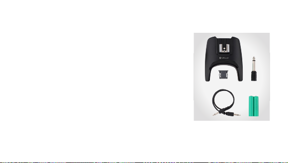
CONTENTS
FreeWave Mini-Stand Flash Trigger (FW-MS)
• FreeWave Mini-Stand
Transmitter
• FreeWave Mini-Stand
Receiver
• 3.5 mm to 3.5 mm sync
cable
• 3.5 mm to /4" phono
adapter
4
• 2 × AAA alkaline batteries
• CR2032 3 V battery
• Hot-shoe flash mount cover
• Instruction manual
Page 5
FreeWave Mini-Stand Receiver (FW-MSR)
• FreeWave Mini-Stand
Receiver
• 3.5 mm to 3.5 mm sync
cable
• 3.5 mm to /4" phono
adapter
• 2 × AAA alkaline batteries
• Hot-shoe flash mount cover
• Instruction manual
5
Page 6

KEY FEATURES
• Stand and Receiver
as One
By having the stand and
receiver built together, you
can place the flash where
you need without additional
equipment.
• Sleek Design
Low-profile and sleek design
provide a professional look.
6
• Wireless Hot-Shoe
Flash Trigger Set
Trigger a hot-shoe flash
(on-camera type) up to 200'
(60 m) away.
• Low-Interference Signal
It provides low interference
around and through
obstructions with a robust
2.4 GHz signal.
• Wireless Studio Light
Trigger Set
Trigger a studio light up to
200' (60 m) away.
• Simple Pairing System
Get setup quickly with the
easy two-button pairing
between the transmitter
and receiver.
Page 7
• Multiple Flash
Triggering
Pair multiple receivers
(available separately) as
needed to trigger many
flashes with a single
transmitter.
COMPATIBLE DEVICES
The FreeWave Mini-Stand
Flash Trigger set is compatible
with hot-shoe flashes that
have manual settings, studio
lights, and DSLR cameras.
Pentax, Sony/Minolta, and Sony
Multi-Interface Shoe (MIS)
flashes are not compatible.
7
Page 8

PRECAUTIONS
• There are no userserviceable parts inside the
devices. Do not attempt to
disassemble or perform any
unauthorized modification.
• Turn o the camera before
inserting or removing the
Mini-Stand Flash Trigger.
• Do not operate in the
presence of flammable gas
or vapors.
8
• Turn o the receiver and
flash before inserting or
removing any piece of
equipment.
• Observe caution when
handling batteries. Batteries
may leak or explode if
improperly handled. Use
only the batteries listed in
this manual. Make certain to
align the batteries with the
correct polarity.
• Do not handle with wet
hands or immerse in or
expose to water or rain.
Failure to observe this
precaution could result in
fire or electric shock.
• Keep out of reach of
children. This device
contains small parts which
may pose a shocking hazard.
• Handle the unit with care.
Page 9

• Batteries are prone
to leakage when fully
discharged. To avoid damage
to the product, be sure
to remove the batteries
when leaving the product
unattended for prolonged
periods or when no charge
remains.
• Please read and follow these
instructions, and keep this
manual in a safe place.
• Do not use or leave the
devices in conditions of
extreme heat, severe cold,
or high humidity.
• Dispose of used batteries,
packaging, and old
devices in accordance
with appropriate local
environmental regulations.
• Clean the unit with a soft,
dry cloth.
• Use only parts provided by
the manufacturer.
• Make sure the item is
intact and that there are no
missing parts.
• All photos are for
illustrative purposes only.
9
Page 10
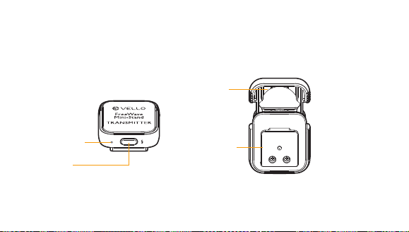
OVERVIEW
Transmitter
Status
indicator light
Pairing/test
button
0
To p Bottom
Battery
drawer
Mounting
foot
Page 11

Receiver
Hot-shoe
flash mount
Power switch
Status indicator light
To p
Back
Rubber
pads
/4"-20
threaded
female
mount
3.5 mm
output sync
Bottom
FreeWave Mini-Stand REC EIVER
Code Set
Battery
compartment
Transmitter
code set
button
(recessed)
Battery
compartment
cover
Page 12

INSTALLING BATTERIES
Installing the Battery into the Transmitter
. Pull the battery drawer
out. It will come out only
halfway.
2. Insert the CR2032 battery
at a slight angle and with the
(+) side up, as indicated.
2
3. Close the battery drawer
until it locks.
Note: There is no power switch
for the transmitter. It will stay on
constantly, drawing power when
the button is pressed for testing,
or when the unit is transmitting a
signal to the receiver.
Page 13

Installing the Batteries into the Receiver
. Slide the battery
compartment cover open
until it clicks and can be
removed.
2. Insert the two AAA
batteries into the battery
compartment. Take note
of the (+/−) symbols and
match up accordingly with
the image guide.
3. Reattach the battery
compartment cover by
positioning it over the
battery compartment and
sliding it back into place
until it locks.
3
Page 14

PAIRING THE TRANSMITTER TO A RECEIVER
Note: The transmitter and
receiver sets come paired
together.
. Slide the receiver’s
battery compartment
cover towards the rear
for removal and turn the
receiver on.
4
2. Press the recessed
transmitter code set
button. Use a pin-like
object that will fit into the
recessed hole.
3. After pressing the button,
the status indicator light
will blink repeatedly. This
signals that the receiver is
in pairing mode and is ready
to receive the transmitter’s
code. After 5 seconds, the
receiver will exit pairing
mode.
Page 15

4. Press the pairing/test button
on the transmitter. The
receiver’s status indicator
light will blink twice, and
then continue to blink
repeatedly. After 5 seconds,
the receiver will exit pairing
mode.
5. Both the transmitter
and the receiver should
now be paired. To verify
communication, press the
transmitter’s pairing/test
button. The indicator light
on the receiver will register
one quick blink.
6. Reattach the receiver’s
battery compartment cover.
5
Page 16

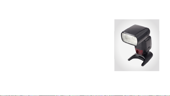
MOUNTING A FLASH TO THE RECEIVER
. Make sure your flash and
receiver are turned o.
2. Slide the flash’s mounting
foot all the way into the
hot-shoe mount of the
receiver.
6
3. Secure the flash by engaging
its locking mechanism.
4. Turn on the flash and
receiver.
5. Set the flash to Manual
mode and adjust its settings.
6. Press the pairing/test button
on the transmitter. The
flash should fire with each
press.
Page 17

MOUNTING THE TRANSMITTER TO YOUR CAMERA
. Make sure you camera is
turned o.
2. Slide the transmitter’s
mounting foot all the way
into the camera’s hot-shoe
mount.
3. Turn your camera on.
4. Press your camera’s shutter
release button. At this time,
the flash will fire with each
press of the shutter.
7
Page 18

PAIRING THE TRANSMITTER TO MULTIPLE RECEIVERS
Note: Repeat these steps, one at
a time, for each receiver that will
be paired with your transmitter.
There is no limit as to how many
receivers can be paired to one
transmitter.
. Slide each receiver’s battery
compartment cover toward
the rear for removal and
turn the receivers on.
8
2. Press the recessed
transmitter code set button
on the first receiver. Use a
pin-like object that will fit
into the recessed hole.
3. After pressing the button,
the status indicator light
will blink repeatedly for
5 seconds. This signals
that the receiver is in
pairing mode and ready to
Page 19

receive the transmitter’s
code. After 5 seconds, the
receiver will exit pairing
mode.
4. Press the pairing/test button
on the transmitter. The
receiver’s status indicator
light will blink twice, and
then continue to blink
repeatedly for up to 5
seconds.
5. Both the transmitter
and the receiver should
now be paired. To verify
communication, press the
transmitter’s pairing/test
button. The indicator light
on the receiver will register
one quick blink.
6. Repeat steps -5 for each
receiver.
9
Page 20

7. Reattach the battery
compartment cover for
each receiver.
8. Have your receivers and
flash units turned o before
mounting each flash to its
corresponding receiver.
20
9. After each flash is mounted
to a receiver, turn the units
on. Set each flash to its
manual setting and adjust
accordingly.
0. Press the pairing/test button
on the transmitter. All
of the flashes should fire
together.
Page 21

PAIRING A RECEIVER TO MULTIPLE TRANSMITTERS
. Make sure you have all of
your transmitters handy and
in a line, ready to be paired
to the one receiver.
2. Slide the receiver’s
battery compartment
cover towards the rear
for removal and turn the
receiver on.
3. Press the recessed
transmitter code set button
on the receiver. Use a pinlike object that will fit into
the recessed hole.
4. After pressing the button,
the status indicator light
will blink repeatedly for
5 seconds. This signals
that the receiver is in
pairing mode and is ready
to receive a transmitter’s
2
Page 22

code. After 5 seconds, the
receiver will exit pairing
mode.
5. Press the pairing/test button
on the first transmitter. The
receiver’s status indicator
light will blink twice, and
then continue to blink
repeatedly for up to 5
seconds.
22
6. In these 5 seconds, you
will need to press the
pairing/test button on
the next transmitter, and
so on for the remaining
transmitters. The receiver’s
status indicator light
will blink twice and then
flash repeatedly again
for 5 seconds after each
transmitter has been paired.
Page 23

7. The transmitters and
receiver should be paired
at this time. Press each
transmitter’s pairing/
test button and watch
the indicator light on the
receiver for one quick blink.
8. Reattach the battery
compartment cover for
each receiver.
9. Have your flash unit turned
o and attach it to the
receiver.
0. Turn the flash on and press
the pairing/test button on
each transmitter. Each of
the transmitters should fire
the flash unit.
Note: A receiver can store up to
5 transmitter codes. Each time
a receiver enters pairing mode
and a new Transmitter’s code is
stored, it will delete all previously
stored codes.
23
Page 24

CONNECTING THE RECEIVER TO A STUDIO LIGHT
. Turn the receiver and your
studio light o.
2. Use the included 3.5 mm
to 3.5 mm cable to connect
the output sync port on the
receiver to the flash sync
port on your studio light.
3. Turn the receiver and your
studio light on.
24
Note: Your studio light might have
a 1/4" phono port for syncing
the flash. We have included the
necessary adapter to convert
3.5 mm to 1/4".
Page 25

MOUNTING THE RECEIVER TO A LIGHTING STAND
. Place the receiver’s /4"-20
mount onto the lighting
stand mounting stud.
2. Rotate the receiver until
the unit is secure on the
lighting stand.
3. Attach your flash unit to
the receiver's hot-shoe
mount.
25
Page 26

TROUBLESHOOTING
The transmitter does
not send a signal.
• Check that the transmitter’s
battery polarity has not
been reversed.
• The battery has run out
of power and needs to be
replaced.
26
The receiver is
not accepting the
transmitter’s code(s).
• Reset the code between
the receiver and the
transmitter(s) (see page 4).
The flash does not
fire or misfires.
• Check the batteries of each
device for low power and
replace if needed.
• Check whether the
receiver’s power switch is in
the On position.
• Reset the code between
the receiver and the
transmitter(s) (see page 4).
• Check whether the flash is
in manual mode.
Page 27

FCC COMPLIANCE
This device complies with
Part 5 of the FCC Rules.
Operation is subject to the
following two conditions:
. This device may not cause
harmful interference, and
2. This device must accept
any interference received,
including interference
that may cause undesired
operation.
27
Page 28

SPECIFICATIONS
Transmitter Receiver
Dimensions (H × W × D)
Devices paired Up to 5 transmitters Unlimited
Tripod mount n/a /4"-20
3.5 mm to 3.5 mm sync cable length 2" (30 cm)
0.55" × .7" × .34"
(.4 × 3 × 3.4 cm )
28
0.87" × 3.8" × 3.78"
(2.2 × 8. × 9.6 cm)
Page 29

Transmitter Receiver
Frequency 2.4 GHz
Battery CR2032 3 V battery 2 × AAA alkaline batteries
Battery life (in standby mode) 5 yr. 20 hrs.
Range 200' (60 m)
Weight 0.04 oz. (.3 g) 2.7 oz. (77 g)
29
Page 30

ONE-YEAR LIMITED WARRANTY
This VELLO product is warranted to the original purchaser to be free from defects in materials
and workmanship under normal consumer use for a period of one () year from the original
purchase date or thirty (30) days after replacement, whichever occurs later. The warranty
provider’s responsibility with respect to this limited warranty shall be limited solely to repair or
replacement, at the provider’s discretion, of any product that fails during normal use of this product
in its intended manner and in its intended environment. Inoperability of the product or part(s)
shall be determined by the warranty provider. If the product has been discontinued, the warranty
provider reserves the right to replace it with a model of equivalent quality and function.
This warranty does not cover damage or defect caused by misuse, neglect, accident,
alteration, abuse, improper installation or maintenance. EXCEPT AS PROVIDED HEREIN,
THE WARRANTY PROVIDER MAKES NEITHER ANY EXPRESS WARRANTIES NOR ANY
IMPLIED WARRANTIES, INCLUDING BUT NOT LIMITED TO ANY IMPLIED WARRANTY OF
MERCHANTABILITY OR FITNESS FOR A PARTICULAR PURPOSE. This warranty provides you
with specific legal rights, and you may also have additional rights that vary from state to state.
30
Page 31

To obtain warranty coverage, contact the Vello Customer Service Department to
obtain a return merchandise authorization (“RMA”) number, and return the defective
product to Vello along with the RMA number and proof of purchase. Shipment
of the defective product is at the purchaser’s own risk and expense.
For more information or to arrange service, visit www.vellogear.com
or call Customer Service at 22-594-2353.
Product warranty provided by the Gradus Group.
www.gradusgroup.com
VELLO is a registered trademark of the Gradus Group.
© 205 Gradus Group LLC. All Rights Reserved.
3
Page 32

www.vellogear.com
All other trademarks are the property of their respective owners.
© Copyright 205 Gradus Group GG1
 Loading...