

Page 1
FREEWAVE
MICRO
WIRELESS REMOTE
SHUTTER RELEASE
USER’S MANUAL
Page 2

2
INTRODUCTION
Thank you for choosi ng the
Vello FreeWave M icro Wirel ess
Remote S hutter Release for
Nikon. T his compa ct set inclu des
a small t ransmit ter and a low profile r eceiver th at sits dir ectly
on the 10-pin remote terminal—
it does n’t require a ca ble or take
up space on the hot sho e. The
FreeWave Micro wirele ssly
trig gers the sh utter of your Nikon
DSLR c amera fro m a distanc e of
approx imately 3 00' so th at you
can sho ot action w hile keepin g
your dis tance from the camer a
setup. You ca n use any one of
16 selec table rad io frequen cies
(channe ls)—th is ensure s that you
have a cle ar channe l for opera ting
your camera even if o ther
wirel ess device s are opera ting in
the same area.
The FreeWave Micro tra nsmitte r
and rece iver fit easily into a shirt
pocket —toge ther they we igh
only 1.1 oz. The t ransmit ter
oper ates using o ne AAA b attery.
The rece iver is powe red by the
camera.
Using t he FreeWave Micr o, you
can activate aut ofocus, trigger th e
shutter, and open and c lose the
shutter when you r camera i s in
Bulb ex posure mod e. A shooti ng
alarm L ED on the tr ansmitt er
blink s red each time a picture i s
taken , so that you’l l always kn ow
the exp osure was m ade.
The FreeWave Micro also a llows
you to ta ke photogr aphs with out
touching your camera—a g reat
advan tage when doing close -up
or macro photogr aphy, or when
you’re usi ng long expo sures. Us ing
the FreeWave Micro, you won’t
risk acc idental ly moving you r
camera.
Page 3

KEY FEATURES
Small, Lightweight Remote Control: compatible
with Nikon DSLRs with a 10- pin remote
terminal.
2.4 GH z Radio Frequency: reduced interference
and imp roved wireless signal q uality.
Exten ded Range: operate s at up to 328 ' (100 m),
depending on conditions.
16 Chann els: oper ates wit hout inter ference f rom
other wireless devices.
Built-In Antenna: improves re ception of re ceiver.
Dual-Function Release: press re lease but ton
half way to activate autofocus; pres s fully to tri p
the shutter.
3
Shut ter Trigger Con firmati on: The red le d ON
light on the trans mitter li ghts up eac h time the
camer a shutte r is releas ed, provid ing visual
confir mation tha t a photogr aph has be en taken.
Bulb Mode Release: when the cam era is in Bu lb
mode, t he FreeWave Mic ro remote con trol
can ope n the shutter at the beg inning of th e
expos ure and close the shutter at the end of t he
exposure.
LED Ind icators: LEDs indi cate Focu s, Shutt er, and
Shooting Confirmation.
Works in Extreme Temperatures: operate s in
tempe ratures f rom -4° to 122 °F (-20° to 50 °C).
Page 4

4
PRECAUTIONS
• There are n o user-ser viceab le parts i nside the
devices. Do not attempt to disassemble or perform
any unauthorized modification.
• Do not oper ate in the pr esence of flammable g as
or vapors.
• Do not hand le with wet h ands or imme rse in or
expos e to water or r ain. Fail ure to obser ve this
preca ution can re sult in fire o r electri c shock.
• Observe caution when handling batteries. Batteries
may leak or explode if imprope rly handl ed. Use
only th e batteri es listed i n this manu al. Make
cert ain to align batteri es with cor rect pola rity.
• Batteries are pro ne to leaka ge when fully
disch arged. To avoid da mage to the product, be
sure to re move the bat teries wh en leaving t he
product unattended for prolonged periods or when
no charge remains.
• Do not use or l eave the devi ces in condi tions of
extre me heat, s evere cold, o r high humid ity.
• Dispose of used batteries, pa ckaging , and old
device s in accorda nce with ap propriat e local
environmental regulations.
• Do not atte mpt to disassemble o r repair th e
equip ment— doing so wil l void the war ranty, and
Vello will n ot be respo nsible for a ny damage .
• Handle the unit with c are.
• Keep out of t he reach of ch ildren. Th is device
conta ins small p arts whi ch may pose a choking
hazard.
• Make sure the item is int act and th at there are n o
missing parts.
• All photo s are for illustrative p urposes o nly.
• Please re ad and follow t hese inst ruction s and keep
this ma nual in a safe place.
Page 5
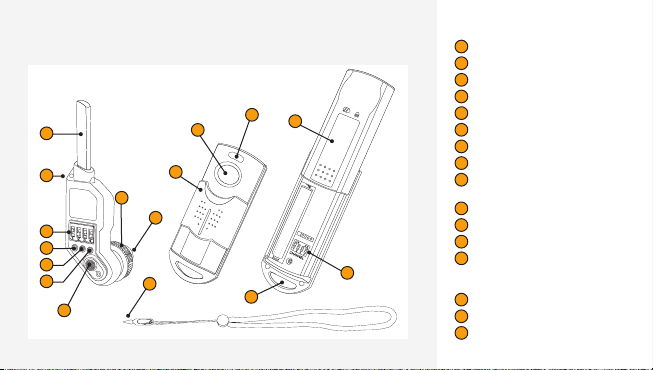
FEATURES DIAGRAM
Receiver
1
2
3
4
5
6
7
11
8
9
10
Lanyard
12
Transmitter
13
15
5
1
Antenna
2
Lanyard hook
3
16-channel switch
4
Power LED
5
14
16
Focus LED
6
Shutter LED
7
Power switch
8
Locking wheel
9
10 pin conn ection to t he
camera.
10
Channel selection pin
11
Protective sliding cover
12
Shut ter relea se button
13
LED Indicator
Focus— vivid blue / Shu tter— dim
blue / Shooting alar m—red
14
Battery compartment door
15
Strap hook
16
16-channel switch
Page 6

6
INSTRUCTIONS
To get the most from your Fre eWave Micro Wire less Remot e Control,
pleas e read this manual.
Setting Up the Receiver
The cam era must h ave a 10-pin
remote terminal in order to
connect with the F reeWave Micro
Wireless Receive r. Please see
the com patible ca mera list on
pag e 12.
1. Inser t the socket o f the
receiver, with the ant enna
pointed up, into th e camera’s
10-pin remote terminal.
2. Turn the rece iver sligh tly
until yo u feel that it’s seated
prope rly in the te rminal.
3. Wh en you have cor rectly
aligned the recei ver with the
10-p in remote te rminal, turn
the locking wheel clockwise
until the receiver i s securely
connected to the c amera.
Page 7

7
4. Turn the re ceiver on by
pressing the power b utton.
5. The r ed Power LED on t he
receiver will blin k on and o
when th e receiver i s connect ed
prope rly to the ca mera.
6. Ens ure that the receiver is set
to the sa me channe l as the
transmitter.
7. To turn the r eceiver o , press
the powe r switch an d hold it
for app roximatel y one second .
The red Pow er LED will turn
o.
Note: The rec eiver will e nter
sleep m ode after it has been o n
for two hours with out being
activ ated. Whe n the recei ver is in
sleep m ode, pres s the On swit ch
to resume operation.
Page 8

8
Setting Up the Transmitter
Please follow the se directi ons to
set up th e transmi tter.
1. Press dow n on the knurled
area on t he back of the
tran smitter a nd slide ope n the
batte ry cham ber cover.
2. Inst all one AA A batte ry in the
batte ry cham ber, ensuring that
the pol arity is co rrect.
3. Using the incl uded chann el
selec tion pin (attached to th e
lanyard), select the channel
using t he selecto r next to the
batte ry. Be sure the channel
match es the chan nel setti ng on
th e re cei ver.
4. Slid e the batte ry cham ber
cover closed.
5. To activate autofocus, press
the shu tter but ton on the
tran smitter h alfway d own.
When au tofocus is e ngaged ,
the indicator LED w ill become
a vivid b lue color.
6. To trig ger the shut ter and
take a photograp h, press th e
shutter butto n all the way
down. W hen the shu tter is
engaged, the ind icator LE D will
turn a di m blue color.
Page 9

SETTING THE CHANNEL
A
B
C
D
There a re 16 radio frequencies (channels) ava ilable
on the tr ansmit ter and the re ceiver. Be sure t o set
the sam e channel o n the trans mitter a nd the recei ver.
This allows you to use t he Freewave M icro Wirel ess
Remote Control without interference from other
device s using rad io frequen cies in the s ame area. T he
chann el select ion pin att ached to the i ncluded l anyard
helps yo u to adjust the channel s. Please refer to the
chann el list bel ow for inform ation abou t setting t he
channels.
Note: Be sure t o maintai n a minimum di stance of 2 0"
(50 cm) bet ween the transmit ter and receiver duri ng
operation to prevent anti-RF interference.
Available Channels
E
I
M
N
9
F
J
G
K
O
H
L
P
Page 10

10
USING THE FREEWAVE MICRO WIRELESS REMOTE SHUTTER RELEASE FOR NIKON
Afte r you attac h the receiver to
your camera, you c an use the
FreeWave Micro to activ ate the
autofo cus funct ion, to rele ase the
shutter, and to oper ate the Bulb
mode on yo ur camer a.
To operate t he autofoc us functi on
on your ca mera, p ress the shu tter
butt on on the tra nsmitte r halfw ay
down. W hen the aut ofocus is
engaged, the blu e LED on the
tran smitter a nd the blue LE D
on the re ceiver will both light
up. To take a pho tograph , press
the shu tter but ton all the w ay
down. T he red LED on th e
receiver and the red s hooting
alarm L ED on the tr ansmitt er
will lig ht up to confi rm that the
receiver is funct ioning and t hat
it has triggere d the shutt er in
the cam era. The c onfirmat ion
light m ay not blink at t he precise
momen t that the photograp h
is taken.
To use the FreeWave M icro with
the Bul b mode on your c amera ,
first se t your came ra to Bulb
mode. T hen, pres s the shutter
butt on on the tra nsmitte r and
hold it until the blu e LED on the
tran smitter t urns o. A blu e LED
and a red LED on the rece iver will
light up, signali ng that the sh utter
of the ca mera is ope n. When
you wan t to close the shutter,
press t he shutte r button on the
tran smitter a gain. The b lue and
red ligh ts on the receiver will go
out, s ignaling t hat the shu tter
has closed.
Page 11

TROUBLESHOOTING
Transmitter Receiver
Transmitter light does not blink Insert a fresh battery into the battery chamber, ensuring that the
Transmitter light blinks, but receiver light does
not blink
Status LED on transmitter blinks at incorrect
times
Status LED on the receiver blinks, but the
camera doesn’t operate
polarity is correct.
Check to be sure that the power switch for the receiver is in the
On position.
Ensure that the receiver and transmitter are set to the same channel.
Insert a fresh battery into the battery chamber, ensuring that the
polarity is correct.
Remove receiver from camera and reinstall it, ensuring that it’s
securely attached.
11
Page 12

12
COMPATIBLE CAMERAS
Nikon® D1 / D1H / D1X / D2 / D200 / D2 H /
D2Hs / D2 x / D2Xs / D3 / D30 0 / D300s /
D3s / D3x / D4 / D4 s / D700 / D80 0 /
D80 0e / D810
Fuji® S5 Pro / S3 P ro
Kodak® DC S-14 N
Page 13

SPECIFICATIONS
- Transmitter Receiver
Frequency 2.427 GHz to 2.457 GHz
Channels 16
Maximum Range 328' (100 m)
Battery 1x AAA Powered by camera
Operating Temperature Range -4 to 122°F (-20 to 50°C)
Dimensions 2.83 × 0.86 × 0.90"
Weight 0.7 oz. (19.8 g) without battery 0.4 oz. (11.3 g)
Total Weight 1.5 oz. (42.5 g)
(82 × 34 × 17 mm)
2.75 × 1.33 × 0.67"
(70 × 22 × 23 mm)
13
Page 14

14
FCC COMPLIANCE
This dev ice compli es with Part 15 of the FCC Ru les.
Oper ation is sub ject to the fo llowing two conditio ns:
1. This devi ce may not cau se harmful i nterfe rence.
2. This dev ice must acc ept any inte rferen ce received ,
includ ing inter ference t hat may caus e undesire d
operation.
Page 15

ONE-YEAR LIMITED WARRANTY
This VEL LO product is war ranted to the o riginal purch aser to be free f rom defects i n materials and wo rkmanship und er normal
consume r use for a period of on e (1) year fro m the origina l purchase da te or thirt y (30) days aft er replacem ent, whicheve r occurs
later. The wa rranty provid er’s responsibi lity with re spect to this l imited warra nty shall be li mited solely to re pair or replace ment,
at the prov ider’s discre tion, of any pro duct that fa ils during no rmal use of thi s product in it s intended manne r and in its intend ed
environ ment. Inoper ability of the pr oduct or part(s) sh all be determin ed by the warr anty provid er. If the product h as been
discont inued, the war ranty provi der reserv es the right to r eplace it wit h a model of equiva lent qualit y and function.
This war ranty does not c over damage or def ect caused by misu se, neglect , accident, a lteration, a buse, impro per installat ion or
mainte nance. EXCEP T AS PROVIDED H EREIN, TH E WARRANTY P ROVIDER MAK ES NEITHER AN Y EXPRESS WA RRANTI ES
NOR ANY I MPLIED WARR ANTIES, IN CLUDING B UT NOT LIMITED TO AN Y IMPLIED WARR ANTY OF MERC HANTABILIT Y
OR FITN ESS FOR A PARTICUL AR PURPOS E. This warra nty provide s you with spec ific legal rig hts, and you may als o have additional
rights t hat vary from st ate to state.
To obtain wa rranty cove rage, contac t the Vello Custome r Service De partment to ob tain a return mer chandise autho rization (“R MA”)
number, and r eturn the def ective produ ct to Vello along wit h the RMA number a nd proof of purc hase. Ship ment of the def ective
produc t is at the purchase r’s own risk and expe nse.
For more i nformation o r to arrange ser vice, visit ww w.vellogear.com or cal l Customer Ser vice at 212-594-2353 .
Produc t warranty pro vided by the Gr adus Group.
www.gradusgroup.com
VELLO is a re gistered trad emark of the Gra dus Group.
© 2014 Grad us Group LLC. A ll Rights Reser ved.
15
Page 16

www.vellogear.com
All othe r trademark s are the proper ty of their res pective owne rs
© Copyr ight 2014 Gra dus Group.
GG2
 Loading...