

Page 1

BG-C14
BAT T ERY GRIP
Designed for the
Canon 5D Mark IV SLR Camera
Page 2

Introduction
Thank you for choosing Vello, and congratulations on
your new BG -C14 battery grip purchase. Enjoy the many
benefits that a bat tery grip offers, such as extended
shooting time and more control and comfort when
shooting in portrait orientation.
The Vello BG-C14 is compatible wi th the Canon 5D
Mark IV SLR camera. The BG-C14 accepts up to two
Canon LP-E6 or LP-E6N rechargeable batteries. This
grip is eq uipped with a n alternate sh utter rele ase butto n,
AF area selection, AF s tar t button, AF point selec tion,
AE lock button, multi-controller button, multi-function
button, and main dial for shooting in a ver tical position.
Please read through this entire
manual before using the BG -C14 bat tery
grip.
2
Page 3

Precautions
1.
The BG-C14 should be used with the compatible
devices specified in this manual.
2.
Use only with the batteries and battery holders
recommended in this manual.
3.
Cover the power terminals with the contac t cap
when the BG-C14 is not in use. This prevent s
electrical shor ts caused by metal object s touching
the power terminals.
4.
When the battery holder is removed from the
grip, remove the batteries or place the holder in
a container to prevent electrical shorts caused by
contact with other metal objects.
5. If you notice smoke, an unusual smell, or noise from
the bat tery pack, discontinue use immedia tely.
Remove the batteries, and take the device to a Vello
authorized reseller.
6.
Turn the grip power off when not shoo ting vertically.
7.
The bat tery level may not display properly if bat teries
are inser ted before mounting the grip.
8. Remove batteries from the grip w hen not in use.
9. D o not at tempt to disassemble.
10. Avoid water or extreme humidit y, and keep in a dr y
and cool place.
11. Keep out of reach of children.
12 . All images are for illustrative purposes only.
OVERVIEW INTRODUCTION
3
ASSEMBLY
Page 4
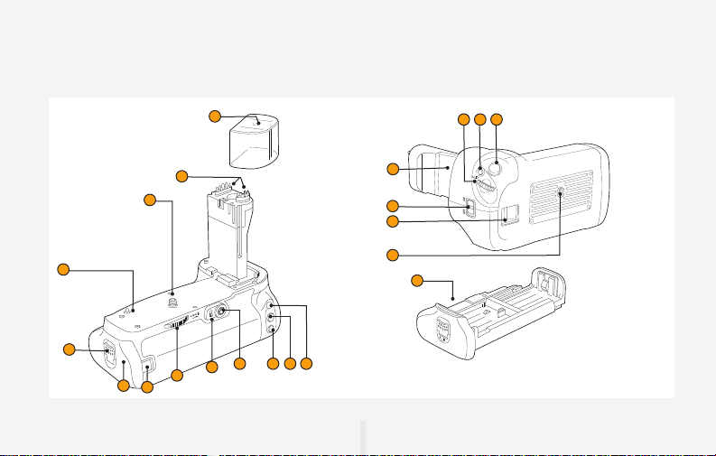
Overview
1
2
3
4
5
8
6
7
1191210 13
17
18
19
20
21
14
1516
4
Page 5

1
Contact Cap
Protec ts grip contacts . Keep covered
when the grip is not in use.
2
Electrical Contacts
Communicate with the c amera
electronics.
3
Mounting Screw
Aligns with the c amera’s tripod so cket.
4
Guide Pin
Helps align the ca mera to the grip.
5
Battery Tray Lever
Locks and unlocks the battery
compartment door.
6
Battery Tray Compartment
Houses the battery tray.
7
DC Coupler Cord Mount
Groove for use with the Canon AC
Power Adapter (ACK-E6).
8
Attachment Wheel
Secures the grip to the camera.
9
AF area selection button*
10
Multi-controller Button*
11
AF Point Selection*
12
AE Lock*
13
AF Start Button*
14
Shutter-Release Button*
15
Multi Function Button*
16
Main Dial*
17
Camera Battery Chamber Cover
Holder
Stores the cover when the grip is
mounted.
18
Grip Power ON/OFF
To prevent accidental triggering, the
Grip Power ON/OFF switch disables
or enables the BG -C14’s controls.
Your camera will continue to draw
power from the BG- C14 when the
switch is in the OFF position. Unlock
prior to use by switching to the ON
position.
19
Hand Strap Mount
20
Tripod Socket
21
Battery Tray
Holds up to t wo Canon LP-E6 or
LP-E6N batteries.
* Performs the same function as on the
camera.
OVERVIEW INTRODUCTION
5
ASSEMBLY
Page 6

Attaching the Grip
1.
Ensure that the power is
turned off on the camera
and that the power switch
is set to OFF on the bat tery
grip.
2.
Open the camera
battery chamber cover,
and remove the bat tery
from the camera battery
compartment.
3.
Slide the camer a battery
chamber cover’s locking
pin, as indicated above, and
remove the cover.
6
Page 7

4.
To prevent loss, remove the
protec tive cap and place the
camera battery chamber
cover into the BG- C14
battery chamber holder as
indicated above. Swing the
battery chamber cover shut
so that it locks into place.
5.
Connect the BG - C14 grip
to the camera.
6.
Rotate the attachment
wheel in the direc tion
shown by the arrow until it
is firmly tightened.
When removing the grip, turn
the camera power of f, remove
the batteries, and replace the
protective contact cap.
OVERVIEW INTRODUCTION
7
ASSEMBLY
Page 8

Inserting Batteries
1.
Ensure that the power is
turned off on the camera
and the grip. Use your
fingernail to protrude the
battery tr ay lever so you can
rotate a nd pull as indicated
above, and slide the battery
tray out of the grip.
2.
Canon LP-E6 or LP-E6N
Batteries: Insert up to
two bat teries by placing
them into either slot in the
battery tray, while ensuring
the correct orientation
as shown on the tray.
8
Household Power Outlet:
The Canon ACK-E6
AC Power Adapter Kit
(sold separ ately) can be
connec ted to the grip. Place
the DC coupler through the
small groove on the back of
the grip. Ensure that the
cord doesn’t get pinched by
the battery holder.
Page 9

3. Rotate the battery tray lever counterclockwise,
and slide the bat tery tray all the way into the grip.
Rotate the lever as indicated above, and push the
it back into place to lock the tray.
4. Switch the grip power to ON, and then turn on
the camera’s power. Check the bat tery level in
the control panel or viewfinder.
OVERVIEW INTRODUCTION
9
ASSEMBLY
Page 10

Specifications
Power Source 1. One or two Canon LP-E6 or LP- E6N rech argea ble bat teries
Operating Temperature 32°F–10 4°F (0°C–40°C)
Dimensions 5.9 × 4.6 × 3.3 in. (15.0 × 11.7 × 8.5 cm)
Weig ht 10.9 oz. (308 g ) excludi ng bat terie s
Specifications and design are subjec t to change wi thout notice.
2. Works with th e Cano n AC Adapte r Kit ACK-E6 (sol d separ ately)
10
Page 11

ONE-YEAR LIMITED WARRANTY
This VELLO product is warranted to the original purchaser to be free from defects in materials and workmanship
under normal consumer use for a period of one (1) year from the original purchase date or thirty (30) days after
replacement, whichever occurs later. The warranty provider’s responsibility with respect to this limited warranty
shall be limited solely to repair or replacement, at the provider’s discretion, of any product that fails during normal
use of this product in its intended manner and in its intended environment. Inoperability of the product or part(s)
shall be determined by the warranty provider. If the product has been discontinued, the warranty provider reserves
the right to replace it with a model of equivalent quality and function.
This warranty does not cover damage or defect caused by misuse, neglect, accident, alteration, abuse, improper
installation or maintenance. EXCEPT AS PROVIDED HEREIN, THE WARRANTY PROVIDER MAKES NEITHER
ANY EXPRESS WARRANTIES NOR ANY IMPLIED WARRANTIES, INCLUDING BUT NOT LIMITED TO ANY
IMPLIED WARRANTY OF MERCHANTABILITY OR FITNESS FOR A PARTICULAR PURPOSE. This warranty
provides you with specific legal rights, and you may also have additional rights that vary from state to state.
To obtain warranty coverage, contact the Vello Customer Service Department to obtain a return merchandise
authorization (“RMA”) number, and return the defective product to Vello along with the RMA number and proof of
purchase. Shipment of the defective product is at the purchaser’s own risk and expense.
For more information or to arrange service, visit www.vellogear.com or call Customer Service at 212-594-2353.
Product warranty provided by the Gradus Group.
www.gradusgroup.com
VELLO is a registered trademark of the Gradus Group. © 2017 Gradus Group LLC. All Rights Reserved.
Page 12

www.vellogear.com
All other trademarks are the property of their respective owners
© Copyright 2017 Gradus Group LLC
GG1
 Loading...