

Page 1
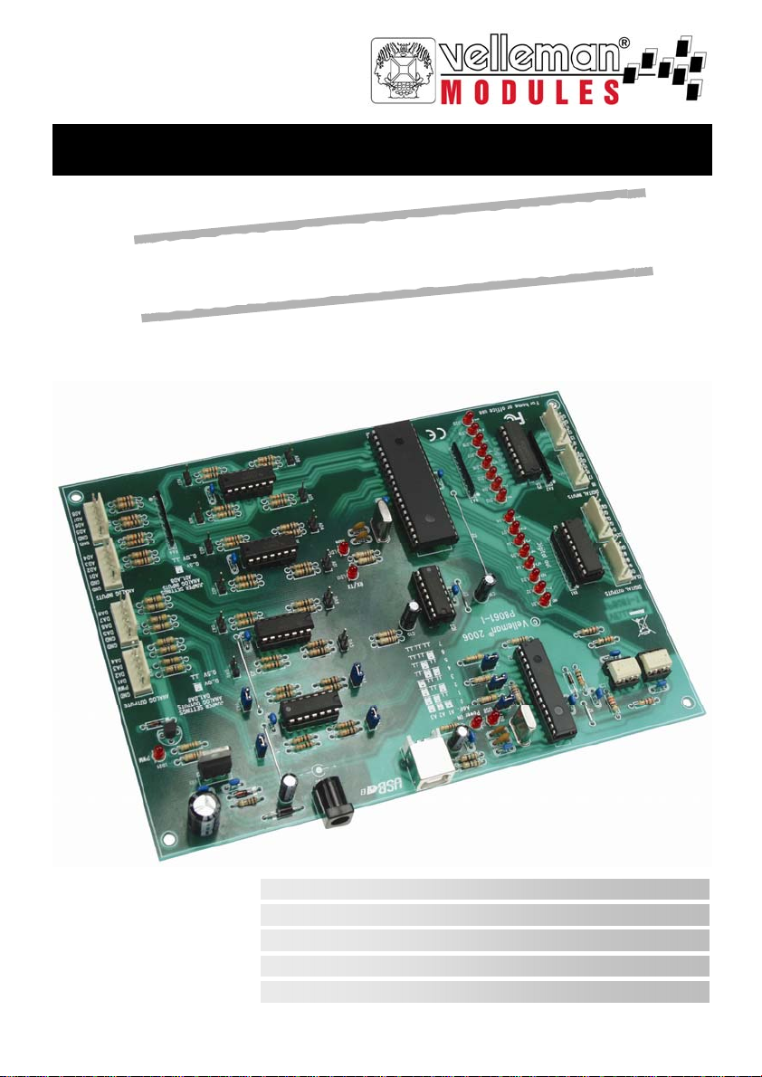
Extended USB interface card
B
S
U
l
a
s
r
e
v
i
n
u
O
/
I
3
3
l
u
f
e
s
u
y
l
l
a
c
i
t
c
a
r
p
A
e
t
n
i
b
e
c
a
f
r
.
d
r
a
o
VM140
VM140
EXT E N DED US B INTERFACE BOARD 3
UITGEBREIDE USB INTERFACEKAART 10
INTERFACE USB - VERSION ETENDUE 17
ERWEITERTE USB-SCHNITTSTELLENKARTE 24
INTERFACE USB DE GRAN EXTENSIÓN 31
Page 2
Velleman Components N. V.
Velleman Components N. V.
Velleman Components N. V.
Legen Heirweg 33
Legen Heirweg 33
Legen Heirweg 33
9890 Gavere, Belgium
9890 Gavere, Belgium
9890 Gavere, Belgium
http://www.velleman
http://www.velleman
http://www.velleman
Kits & Instruments Service Forum : http://forum.velleman.be
Kits & Instruments Service Forum : http://forum.velleman.be
Kits & Instruments Service Forum : http://forum.velleman.be
-
kit.com
kit.com
kit.com
-
-
Page 3

Features & specifications
This computer interf ac e board has a total of 33 in pu ts / outputs, inclu din g analogue / digit al and a
PWM output.
The connection to the computer via the USB port is galvanically-optically isolated, so that damage to
the computer is impossible thus providing a high level of secure implementation.
All communication routines are contained in a Dynamic Link Library (DLL).
You may write custom Windows* Applications in Borland Delphi, Borland C++ Builder, Microsoft
Visual Bas ic , Mic r os of t VC or m ost other 32-bit Windows application devel op m en t tool th at su pp ort s
calls to a DLL.
FEATURES:
8 analogu e 10 bit r es ol ution inputs: 0…5 or 10VDC / 20k ohms
8 analogu e 8 bit resolution ou tputs: 0…5V or 10V DC / 47 ohms
8 digital in puts : open collect or c om patible (connection to GND =0 ) with on-board LED indication
8 digital op en c ollector outpu ts (ma x. 50V/100mA) wit h on-board LED indication
one 10 bit PWM output: 0 to 100 % op en c oll ec tor output (ma x 10 0m A / 40V) wit h on-board LED
indication
USB port: USB 1.1 & 2.0 compatible
SPECIFICATIONS:
• power consumption through USB port: approx. 60mA
• up to 8 cards can be connected to PC
• power supply through adapter: 12VDC / 300mA (PS1205)
• PWM frequency : 15.6kHz
• command execution ti m e: b etw een 21 and 48ms
• PCB dimensions: 195 x 142 x 20m m ( 2. 7 " x 5.6" x 0.8")
MINIMAL SYSTEM REQUIREMENTS:
• Pentium cl ass CPU or hi gher with fr ee USB p ort (1.1 or hi gh er )
• Microsoft Windows 2000 or Windows XP*
• CD-ROM player and mouse
* WinXp recommended for optimum compatibility
* Are registered trademarks of MICROSOFT CORP.
3
Page 4
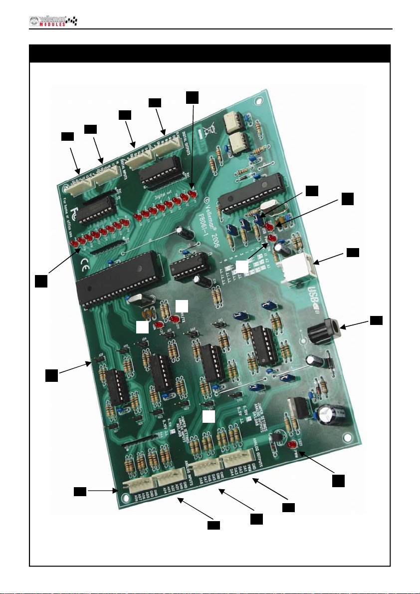
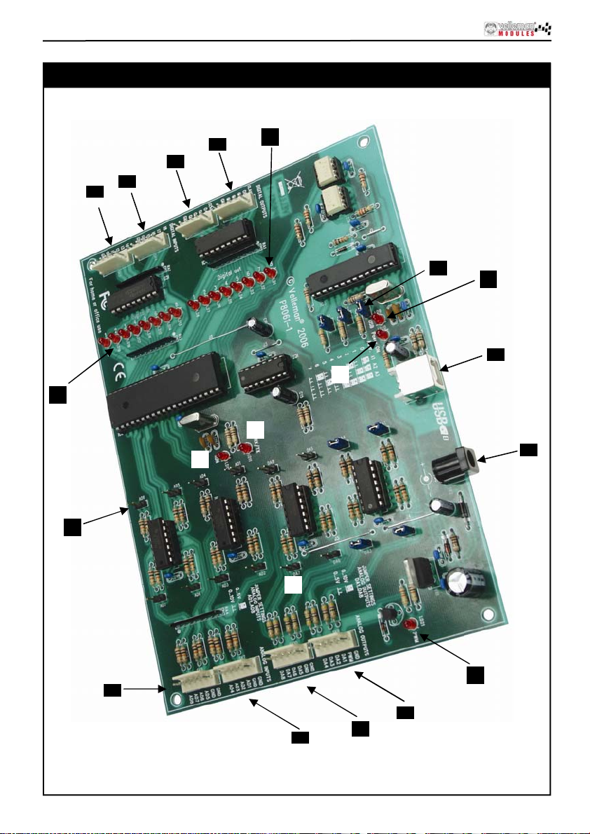
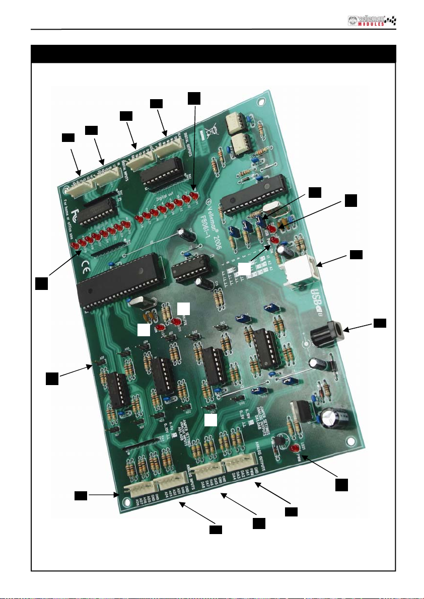
Connections
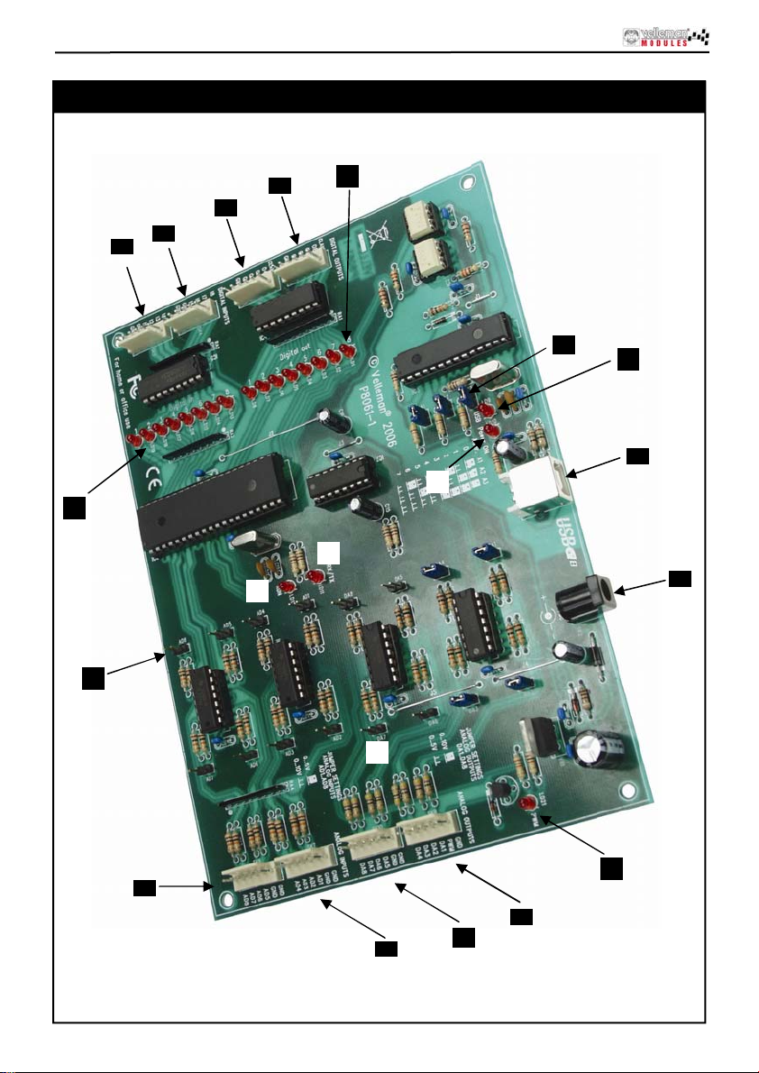
Connections
3
6
5
4
20
19
12
15
16
13
17
11
18
1
2
8
9
7
10
4
14
Page 5
1
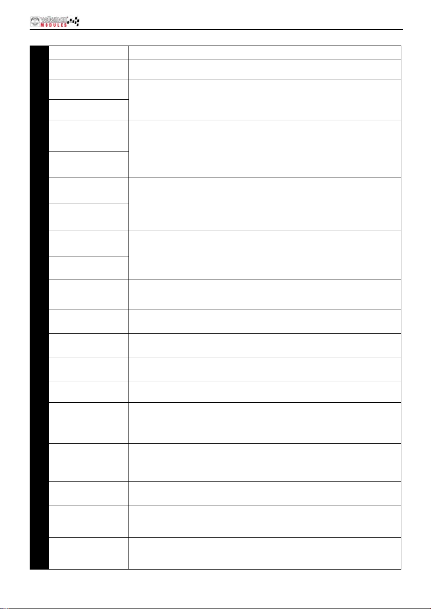
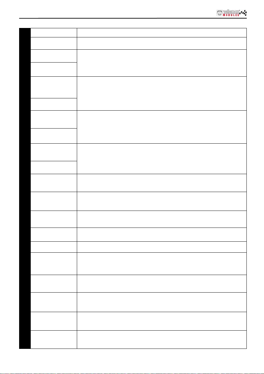
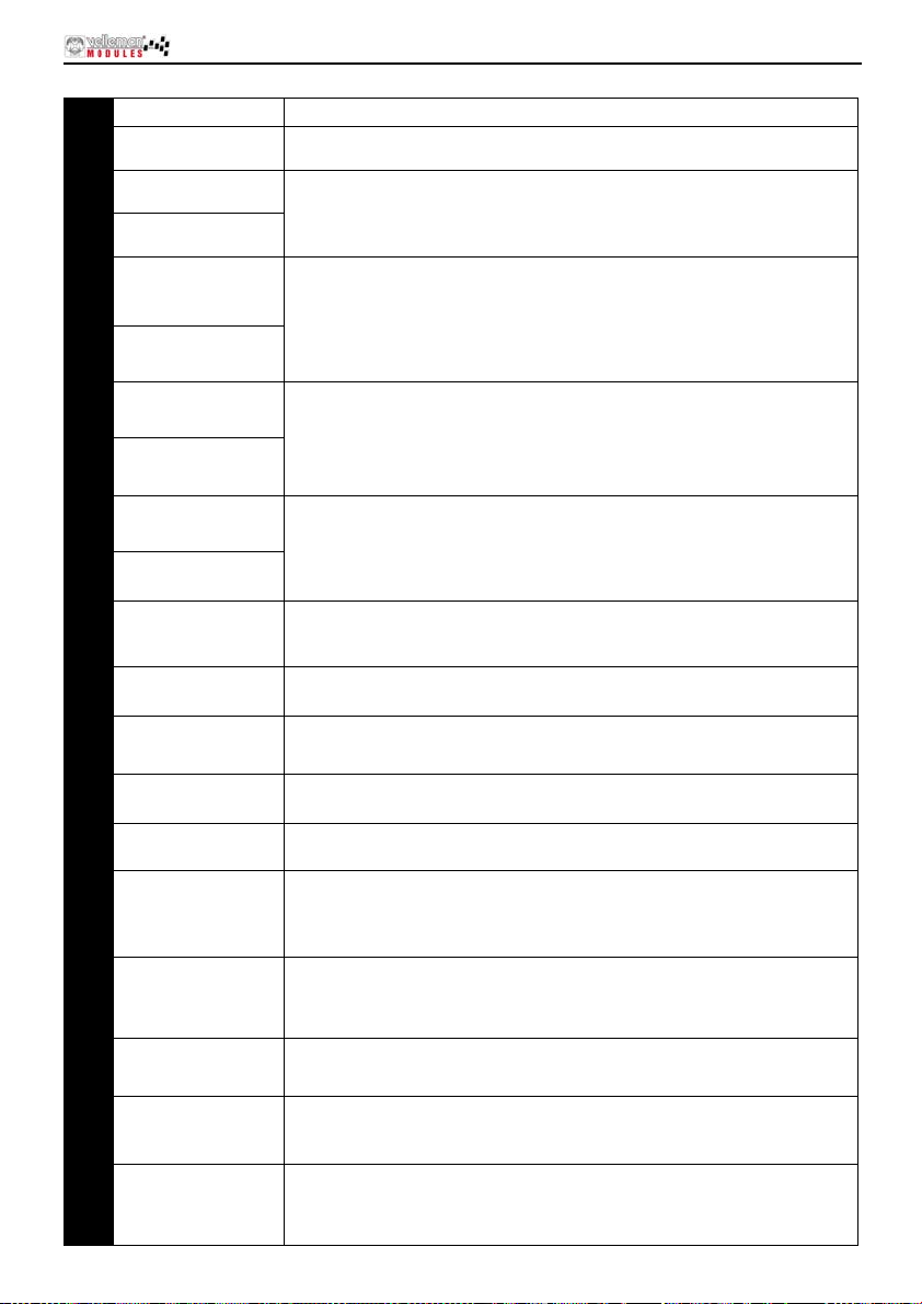
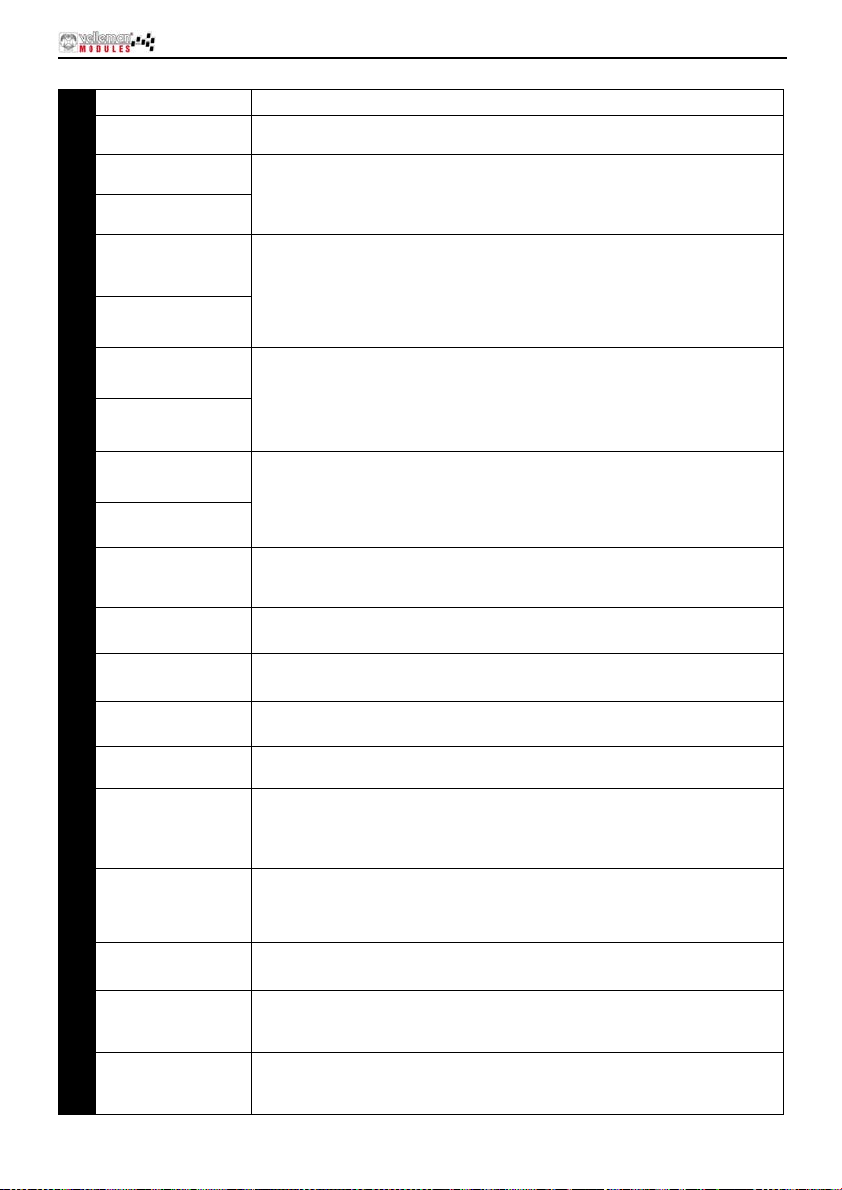
USB-connector Connection of the VM140 with the USB port of your PC
2 12VD C
Digital inputs
3
1, 2, 3, 4
Digital inputs
4
5, 6, 7, 8
Digital outputs
5
1, 2, 3, 4
Digital outputs
6
5,6,7,8
Analogue inputs
7
1,2,3,4
Analogue inputs
8
5,6,7,8
Analogue outputs
9
1,2,3,4
Analogue outputs
10
5,6,7,8
Addressing of the
11
selection ju mpers
12
Max. A/D voltage
Max. D/A output
13
voltage
14
PWM control LED
CPU “run mode”
15
LED
16 CPU RC/TX LED
17 “P OWER ON” LE D
“USB” LED
18
Digital input indica-
19
tion
Power supply connection. C onnect a 12V non-r egulated adapt er supplying
min. 300mA
Inputs need to go “LOW” externally to activate (connect with the GND).
These outputs are open coll ector outputs. When active, the transistors in IC4
will conduct and a “connection” will be established between GND and the
output in quest ion. The charge you wish to feed, lik e a LED, relay …, m ust
receive an external tension. C onnect the “CLAMP” connection with the + of
this external power supply so as to protect the transistor array.
These are measuring points wi t h which you can digitalize and read out an
analogue v oltage through the PC. The analogue in puts expect a DC voltage
between 0 and 5V or between 0 and 10V. Select with the jumpers AD1 to AD8
(see n° 13). A ttention: Supplying a voltage to the A/D inputs high er than 5 or
10V can caus e i rrevocable damage to the VM140 (I C10/11)!
Determination with software of the DC voltage on these output s. Depending
on the jumpers DA1 to DA8 you c an establish this voltage between 0 and 5V
or between 0 and 10V. On pin 2 of this connector (SK9 ) y ou can also find t he
PWM output. T he PWM output is an open collector output whose pulse width
is adjustable.
With the jumpers A1, A2 and A3 y ou c an attribute a uniqu e address to eac h
connect ed VM140. Up to 8 boards can be connected. If you have only 1
VM140, establi sh its addr ess as “0”.
With the jumpers AD1-AD8 you can select the voltage range for t he corresponding A / D i nputs between 0 t o 5V (c losed) or 0 to 10V (open).
With the jumpers DA1-DA8 you can select the max. voltage range for the
corresponding D/A output s between 0 to 5V (open) or 0 tot 10V (closed)
This LED will light if the PW M output is active. The brightness of the LED is
analogous to the pulse/pause relation.
Lights when the CPU of the VM1 40 (IC6) is functioning correctl y.
This LED lig hts in case of data exchange between the CPU and t he USB
interface controller (IC 3). If the LED does not light when the board is
powered, check the USB controller (IC3) or the optical separation (IC1 & 2)
for faults.
Lights in c ase of the presence of t he 5V power suppl y f or t he USB controller.
Attenti on: The VM140 is pow ered through the USB port of your PC and does
not guarantee operation of t he power supply sect ion of the VM140’s CPU and
I/O section.
Blinks during USB connection and lights at every successful c onnection between the USB chip in your PC and the VM140.
These LEDs t urn out when a corres ponding input goes “LOW” (connect ion of
the input wi th GND) through an ext ernal contact or an external open collector
input.
Connections
Digit al ou tp ut in d i-
20
cation
These LEDs li ght i f a corresponding output is activ e, i.e. when a connection is
establish ed between an output pi n and GND (open c ollector output ).
5
Page 6
softwar e ins t allation
Software ins ta llation
After assembly of the circuit, it is now time to install the software drivers and examples and to test
the VM140.
Connect a 12V power supply (non regulated 12V adapter) to the power supply connector of the
VM140 (SK2).
The control LED LD12 (RUN) should light as well as LD13 to LD20 (these are the input control
LEDs and light when the inp uts ar e n ot act ive “LOW” ).
If OK, connect the USB conne ctor of the VM 140 to your PC using the included U SB cable.
LD10 (POWER) should light.
LD10 (USB) should light next in case of a data connection between the PC and the VM140.
With the first connection, you should install the USB driver of the microcontroller onto the PC first.
The location of this driver can be found on the included CD in the ‘USB_driver’ subfolder of the
VM140 software.
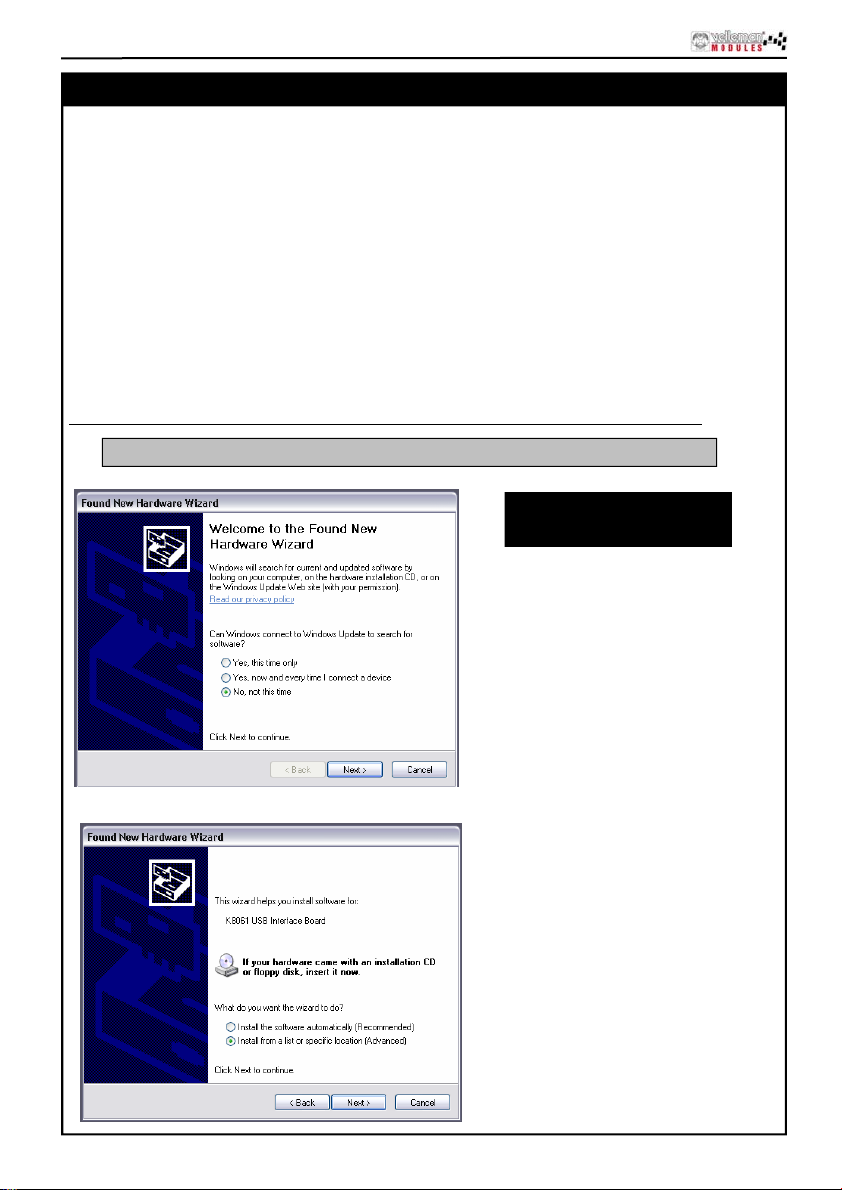
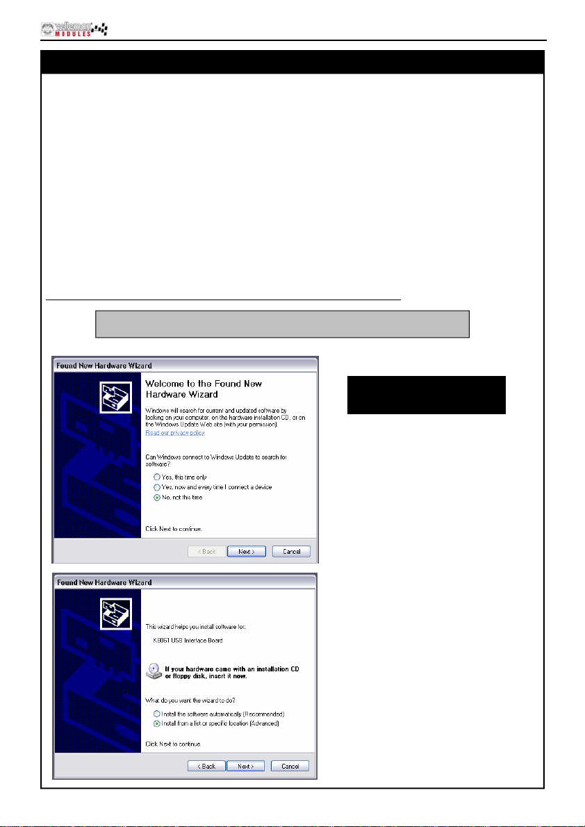
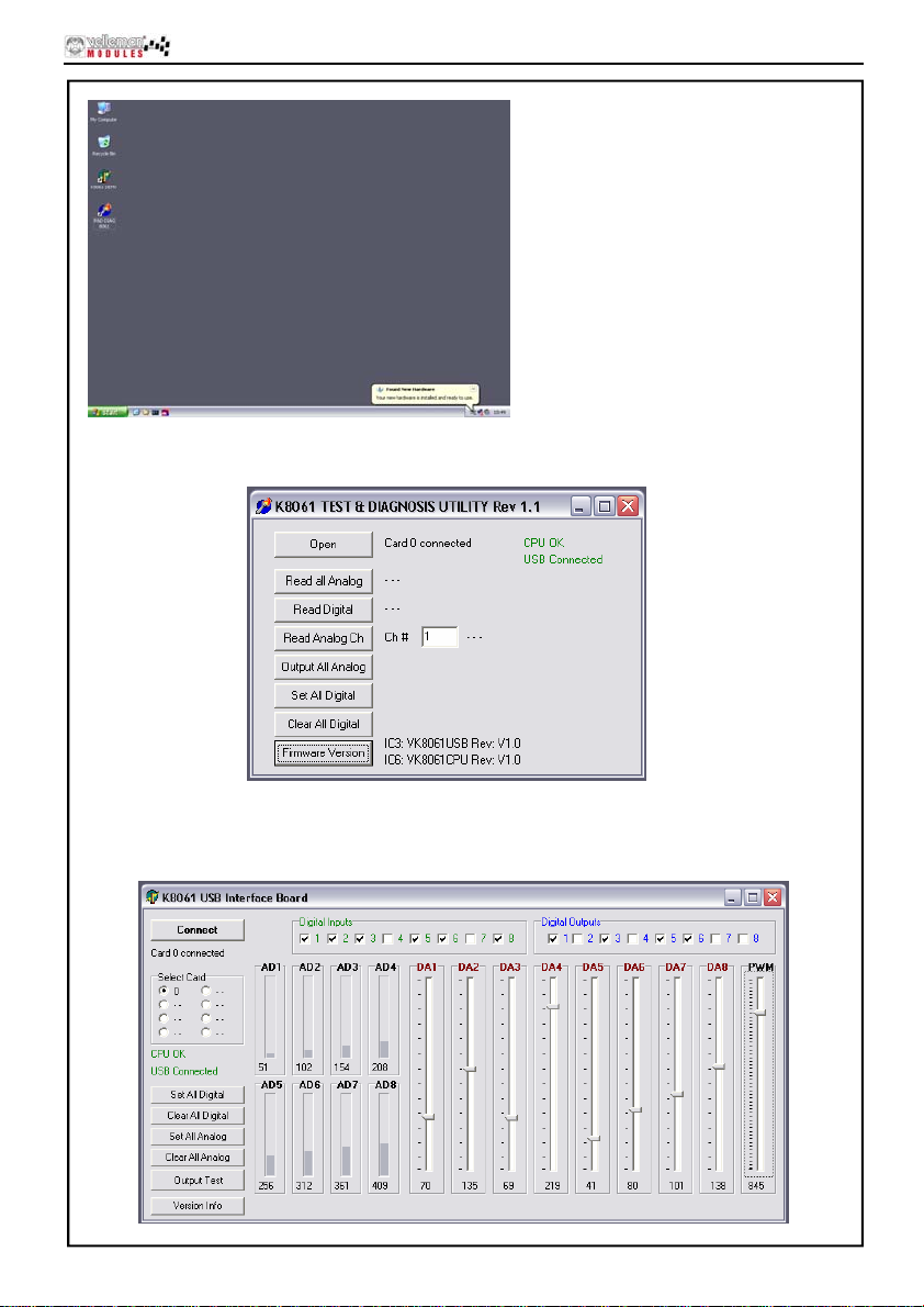
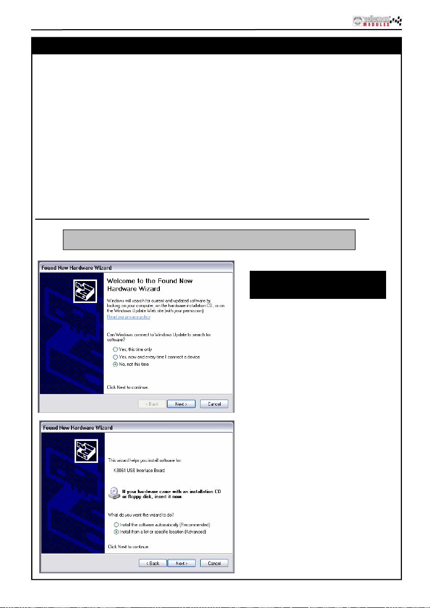
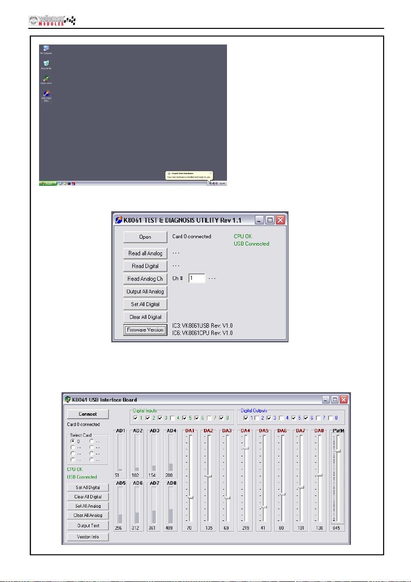
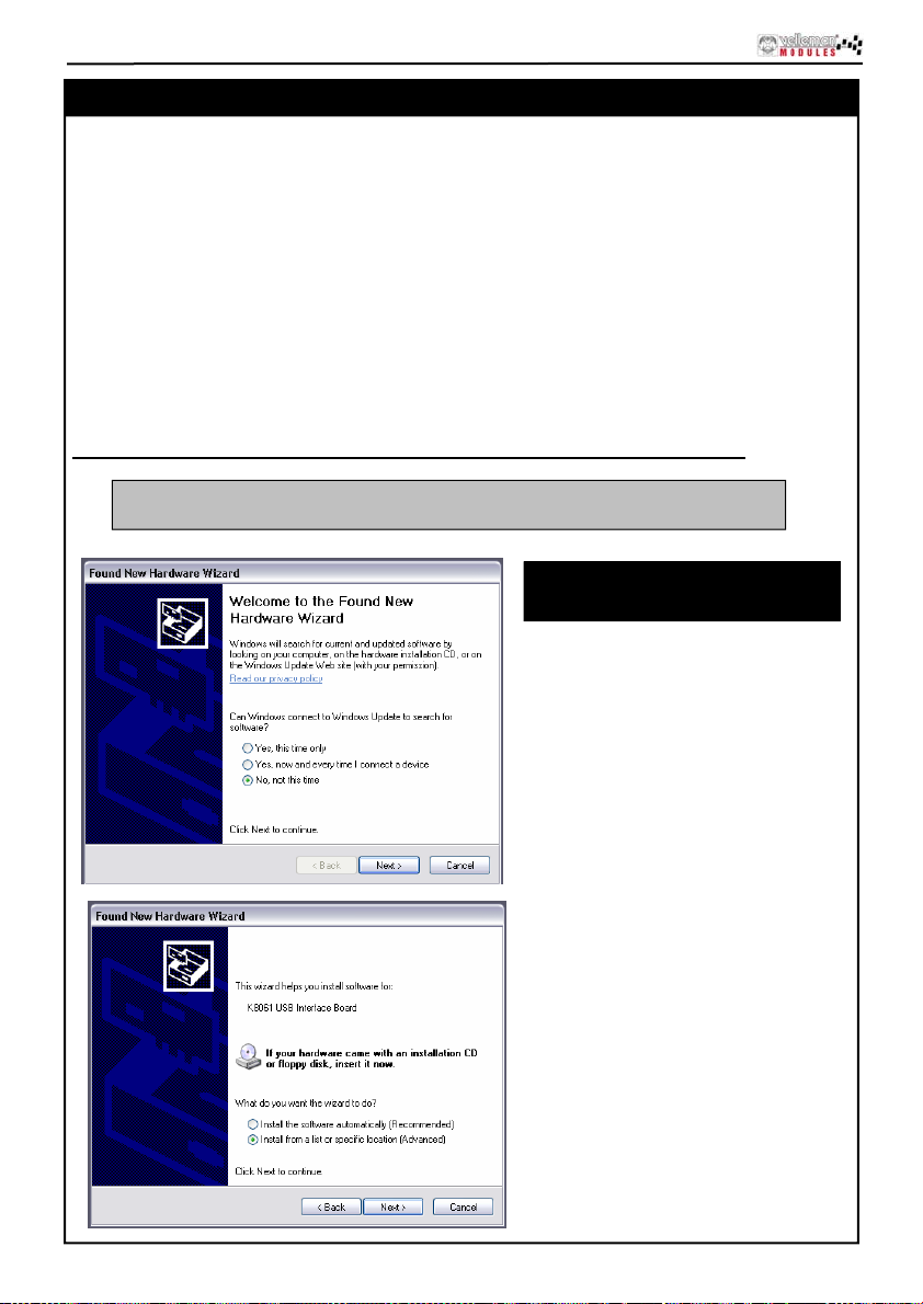
Refer to the figures below illustrating the driver ins tal lation (example Windows XP):
VM140 is the builded version of K8061, software for K8061 is identical for VM140
Screenshots may vary with
different operating system
6
Step 1 : New hardware detected
Local driver, don't run Windows Update
Step 2 : Select "specific location"
Page 7
softwar e ins t all ation
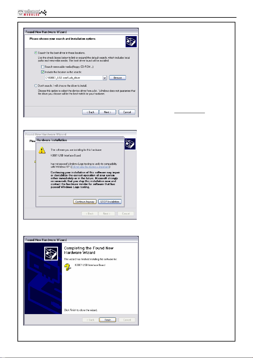
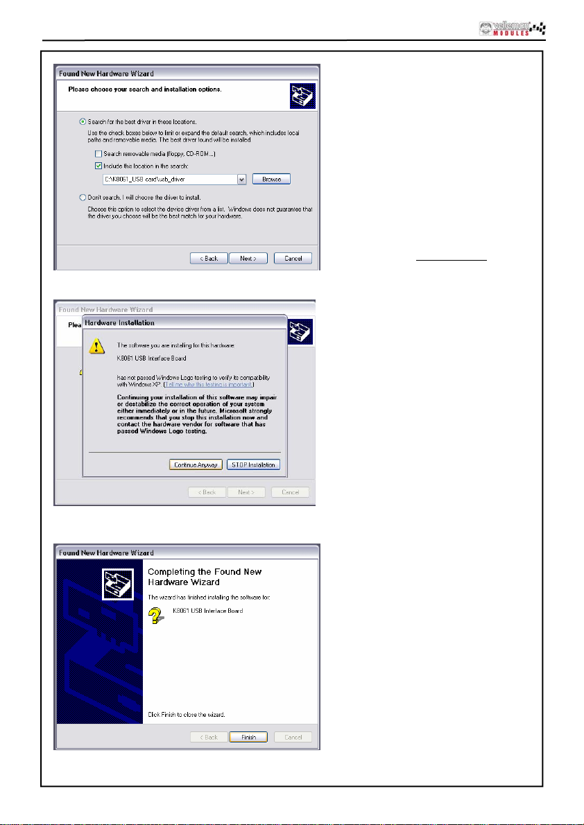
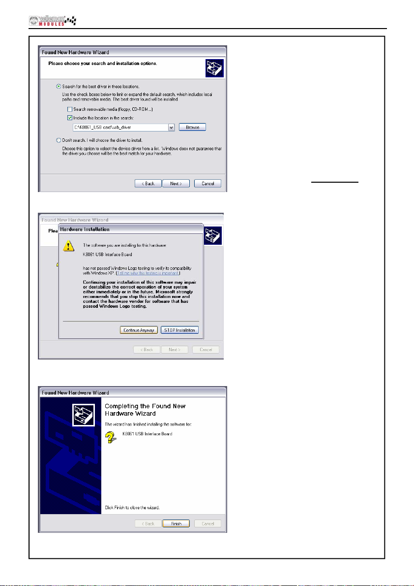
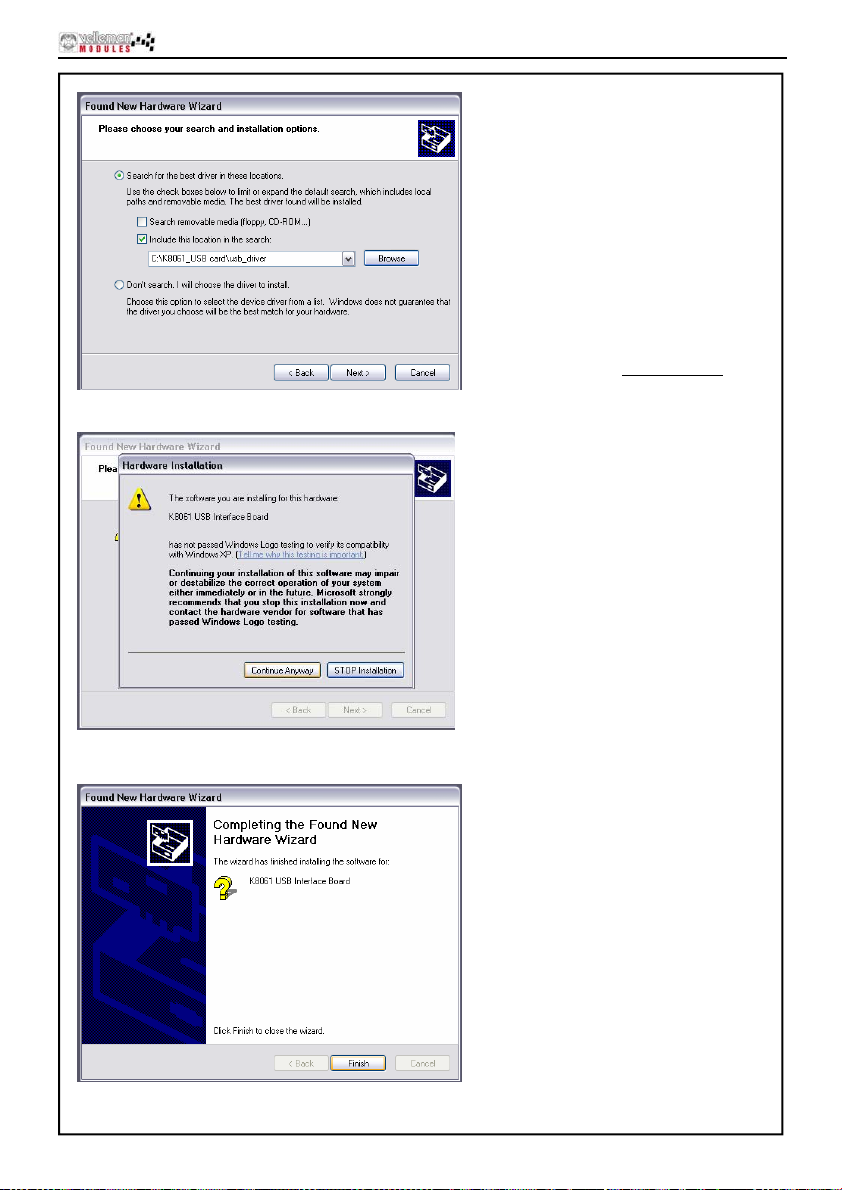
Step 3 : Browse through the driver
folder on your hard disk or inc l u d ed CD.
Select driver : mchpusb.sys
Step 4 : Click "Continue Anyway"
Step 5 : Click "Finish"
7
Page 8
softwar e ins t allation
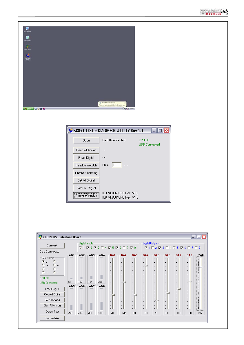
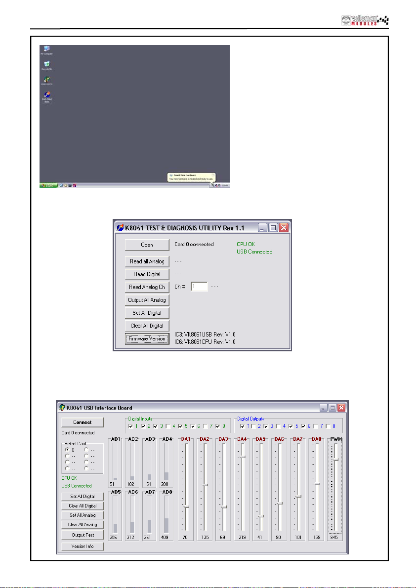
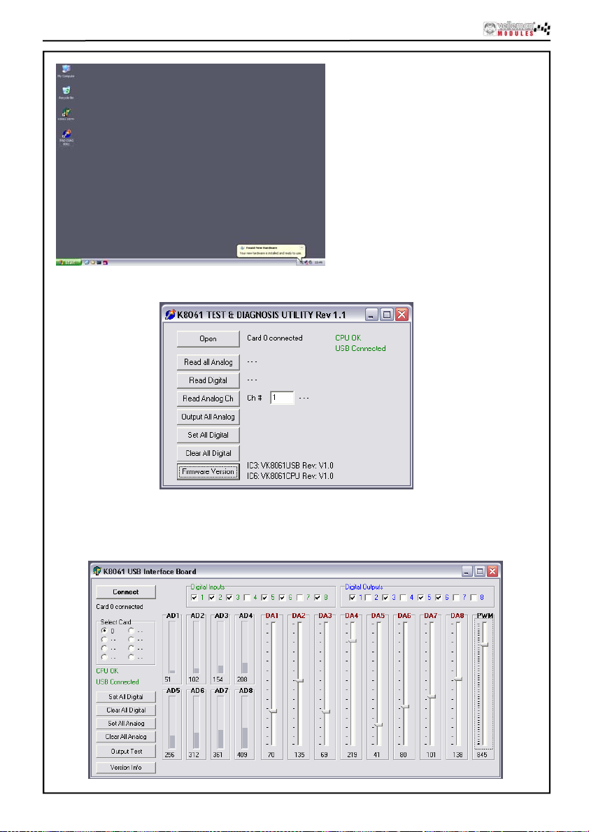
Installation is successful
A utility to check the operation of the VM140 can be found in the “DIAG8061” subfolder.
A more elaborate test application can be found in the “DEMO8061” subfolder.
The source code of the test application can be found in the “DLL examples” subfolder.
Explanation concerning the communication DLL of the VM140 can be found in the “DOC” subfolder.
8
Page 9
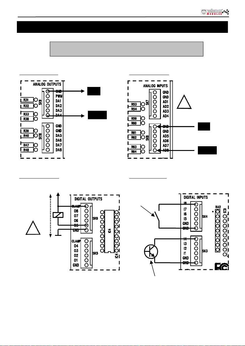
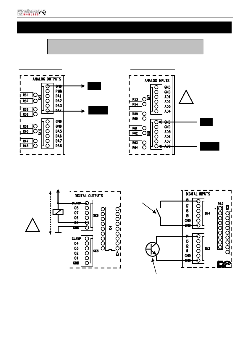
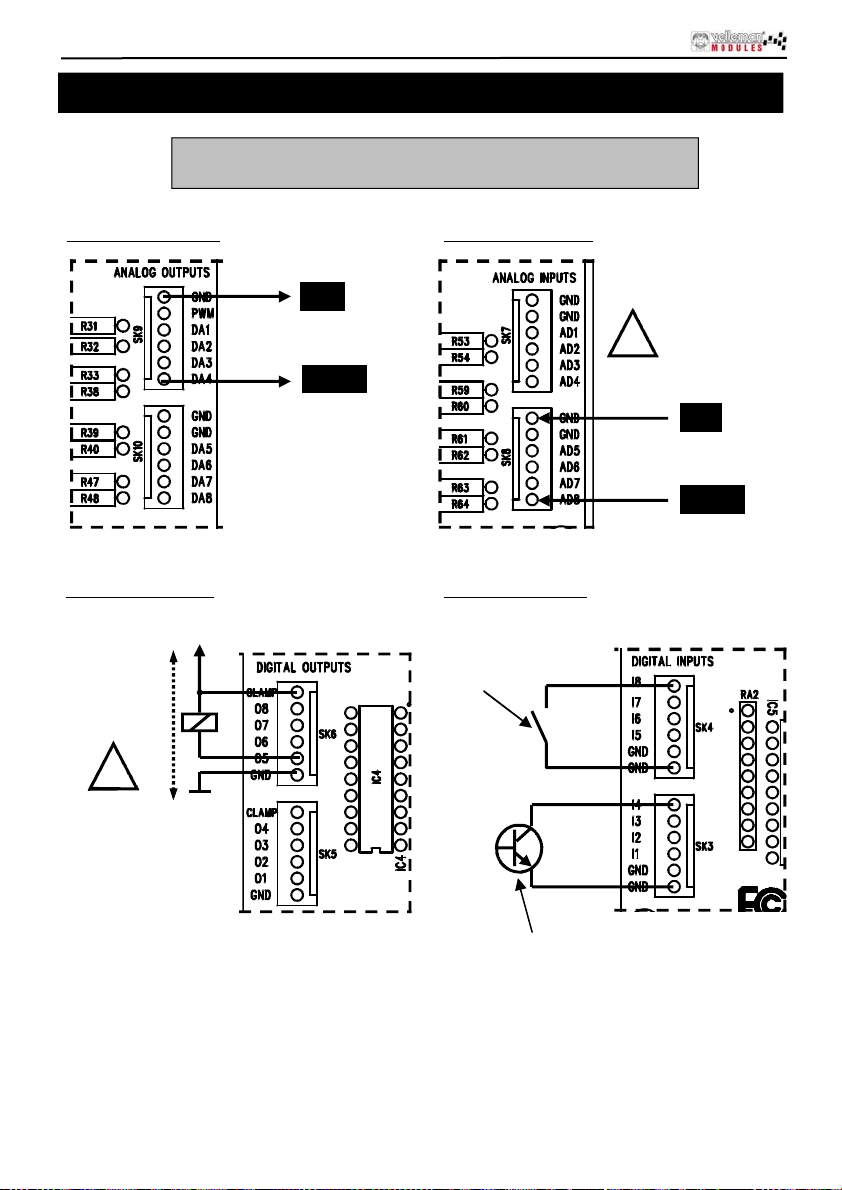
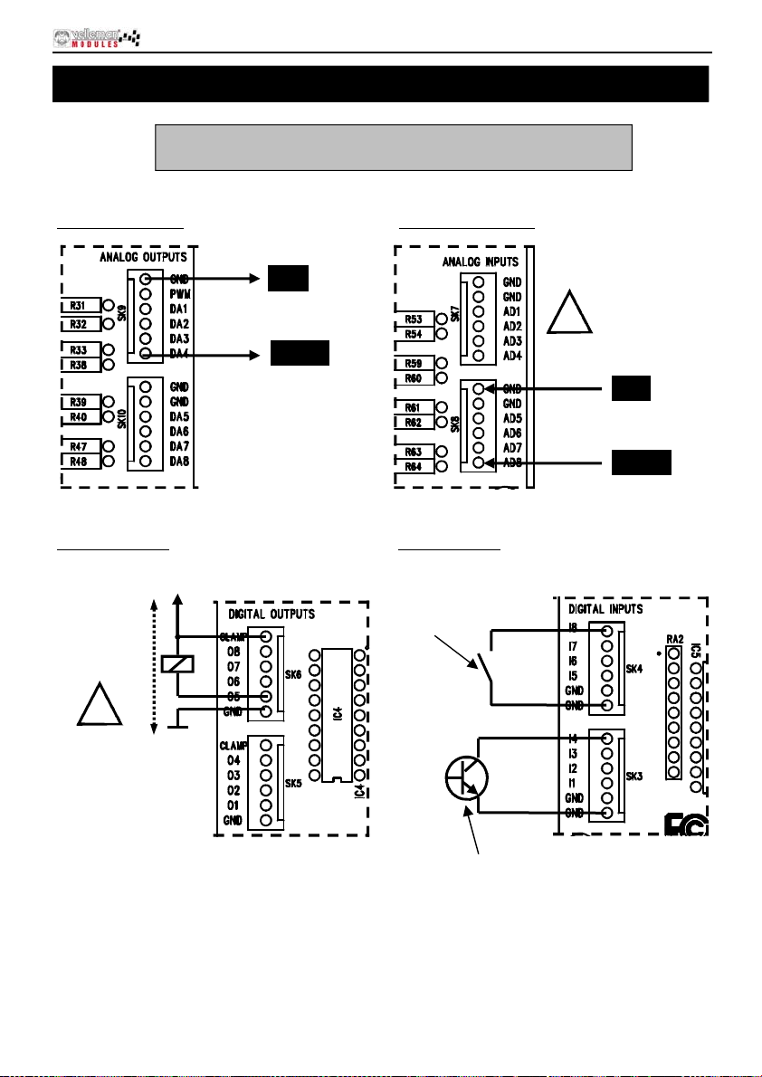
How to connect :
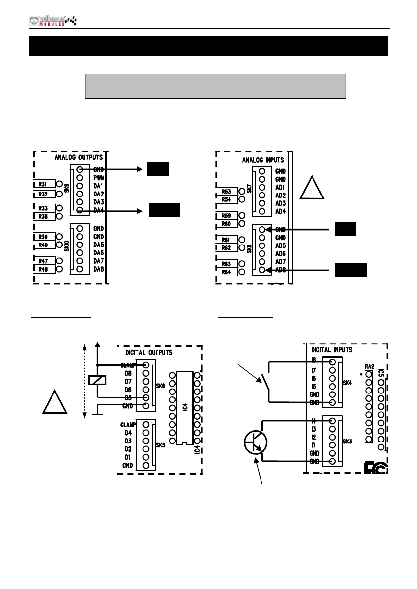
Connect ion example
Check the connections and respect limitations of the specifications
to prevent damage.
1. Analog output :
2. Analog input :
GND
ANALOG OUTPU T VOL T AGE
DAx : +
0 till 5V
OR
0 till 10V
3. Digital output : 4. Digital input :
+V
+V :External
power supply for
relay, LED,
Lamp.
!
MAX 50VDC
GND
Switch, ...
OR
MAX 10V DC !
!
GND
0 ... 5V or 0 ... 10V
ADx : +
External transistor
"open collector" output
9
Page 10

Eigenschappen en technische gegevens
Deze geassembleerde interfacekaart bestaa t uit 33 ingangen / uitga ngen, inclusief analoge / digitale en
een PWM-uitga ng.
De aansluiting naar de computer is galvanisch-optisch geïsoleerd om beschadiging te vermijden en zo de
implementering te beveiligen.
Alle communicatieroutines zi jn in een Dynamic Link Libra ry (DLL) verzameld.
U kunt eigen Windows-toepassingen* schrijven in Delphi, Visual Basic, C++ Builder, Microsoft Visual
Basic, Micro soft VC en de meeste 32-bit Windows-toepassingen die calls naa r een DLL ondersteunen.
EIGENSCHAPPEN:
8 analog e ing an gen met een resolutie van 10 bit : 0…5 of 10VD C / 20 k oh m
8 analog e ing an gen met een resolutie van 8 bit: 0…5V of 1 0V DC / 47 ohm
8 digitale ingangen: open collector compatibel (aansluiting met GND=0) met on-board indicatie-led
8 digital e op encollectoru itgangen (max. 50V/100 mA) met on-boar d in dicatie-led
een PW M- uitg ang van 10 bit: 0 tot 10 0% op encollectoru itgang (max 10 0mA / 40V) met on- b oard
indicatie-led
USB-poort: USB 1.1 & 2.0 compatibel
TECHNISCHE GEGEVENS:
• verbruik langs een USB-po ort: ongeveer 60m A
• mogeli jk h eid om m ax. 8 kaarten met de pc aan t e slui ten
• voeding langs de adapter: 12VDC / 300mA (PS1205)
• PWM- f r equ ent i e: 15 .6 kHz
• stand aard ui tvoeringstijd: tussen 21 en 48 ms
• afmetin gen PCB: 195 x 14 2 x 20 mm
MINIMALE SYSTEEMVEREISTEN:
• Pentium of hoger met vrije USB-poo rt (1.1 of hoger)
• Microsoft Windows 2000 of Windows XP*
• cd-roms peler en muis
* Windows XP is een geregistreerd handelsmerk van Microsoft Corporation.
* Windows XP is aanbevolen
10
Page 11
Aansluitingen
3
Aansluitingen
6
5
4
20
19
12
15
16
13
17
11
18
1
2
8
9
7
10
14
11
Page 12
aansluitingen
1
USB-connector Hier wordt de VM140 met de USB-poort van een pc verbonden.
2 12VDC
Digitale ingangen
3
1, 2, 3, 4
Digitale ingangen
4
5, 6, 7, 8
Digitale uitgangen
5
1, 2, 3, 4
Digitale uitgangen
6
5, 6, 7, 8
Analoge ingangen
7
1, 2, 3, 4
Analoge ingangen
8
5, 6, 7, 8
Analoge uitgangen
9
1, 2, 3, 4
Analoge uitgangen
10
5, 6, 7, 8
Adressering
11
selectiejumpers
A/D maximale
12
spanning
D/A maximale
13
uitgangsspanning
14
PWM controle-LED
CPU “run mode”-
15
LED
16 CPU RC/TX-LED
17
"P OWER ON” - L E D
18 "USB”-LED
Aanduiding
19
digitale ingang
Aanduiding
20
digitale uitgang
Aansluiting van de voedin g. Hier sluit men een 12V ongestabiliseerde adapter op
aan die mi ni maal 300mA kan leveren.
Om ze te activeren dient u deze extern “LAAG” te maken (verbinden met GND).
Deze uitgangen zijn “open col lector ”-uitgan gen, dit wil z eggen dat, als z e actief
word en gemaakt, gaan de transistors in I C4 i n “geleidi ng” en wordt er een
“verbinding” gemaakt tussen GND en de desbetreffende uitgang. De last die u
wenst aan te sturen, zoals een LED, relais ..., moet dus een externe spanning
krijgen, de aansluiting “CLAMP” ver bindt u eveneens met de + van deze externe
voeding. Dit dient om de transistor array te beschermen.
Dit zijn m eetpunten waarmee men een analoge sp anning kan digitaliseren en
uitlezen via de pc. De analoge i ngangen verwachten een stabiele
gelijkspanning tussen 0 en 5V of tussen 0 en 10V. Deze selecti e kan gemaakt
worden met de jumpers AD1 t ot A D8 (zie nr. 13). Opgelet: Een spanning
aanleggen aan de A/D-ingangen groter dan 5 of 10V kan de VM140
onherroepelijk beschadigen (IC10/11)!
Hier kan men softwarematig de gelijkspanning bepalen die u op deze
uitgang en kan plaatsen. Afhankelijk van de st and van de jumper s DA 1 tot DA8
is deze spanni ng in te stellen tuss en 0 en 5V of tussen 0 en 10V . Op pin 2 van
deze connector (SK9) vind u ook de PWM-uitgang. De PWM-uitgang i s een
“open collector”-uitgang waarvan de pulsbreedte regelbaar is.
Met de jum pers A1 , A2 en A3 kunt u elk e VM140 dat aangesloten is een uniek
adres toek ennen. Er kunnen max. 8 kaarten aang esloten worden. A l s u
slechts één VM140 hebt, stel d eze dan in op adres “0 ”.
Met de jum pers A D1-AD8 kunt u het s panningsberei k v oor de
overeenkomstige A/D-in gangen selecteren tussen 0 tot 5V (g esloten) of 0 tot
10V (open).
Met de jum pers DA1-DA8 kunt u het maximale spannings-ber ei k v oor de
overeenkomstige D/A-uitgangen selecteren tussen 0 t ot 5V (open) of 0 tot 10V
(gesloten)
Deze LED licht op indien de PWM-uitgang acti ef is. De helderheid van deze
LED is anal oog aan de puls/pauze verhouding.
Licht op als de CPU van de VM140 (IC6) correct functioneert.
Deze LED licht op als er data wordt uitgewisseld tussen de CPU en de USB
interface controller (IC3). Als deze LED niet oplicht tijdens de werking van de
kaart, i s er een fout in de USB control ler (IC3) of i n de optisch e sc heidin g (IC1 & 2)
aanwezig.
Licht op als d e 5V voeding voor de USB-controller aanwezig is. Opg el et: Deze
voeding w ordt genomen uit de USB-poort van uw pc en is geen garanti e voor
de werking v an het voedingsgedeelte van de VM140’s CPU en I/O -gedeelte.
Knippert tijdens USB-verbinding en licht constant op wann eer er een
geslaagd e communicati e tot stand gebracht is t ussen de USB-chip i n uw pc
en de VM140.
Deze LEDs d ov en als een overeenk omstige ingang “Laag” getrokk en wordt
(verbinding van ingang met GN D) door een extern contact of exter ne “open
collector”-uitgang.
Deze LEDs licht en op als een overeenkomst ig e uitgang act ief wordt, dit wil
zeggen als er een verbinding ont st aat tussen een uitg angspi n en GND (“op en
collector”-uitgang).
12
Page 13
software installatie
Software ins ta llatie
Na het opbouwen van de print is het nu tijd om de software drivers en voorbeelden te installere n en
de VM140 te t esten.
Verbind een 12V voeding (ongestabiliseerde 12V adapte r) met de VM140 voedingsconnector (SK2).
De controle-LED LD12 (RUN) dient op te lichten alsook LD13 tot LD20 (dit zijn de controle-LEDs
van de ing ang en en lic hten op als de ing ang en niet actief “LAA G ” zij n).
Als dit o.k. is, verbindt u de m eeg el everde USB- k ab el m et uw pc en maakt u ver bi nd in g m et de
VM140 USB-connector.
LD10 (POWER) dient nu eerst op te lichten.
Vervolg ens zal LD9 (USB) m oeten oplicht en als er wer k el ij k een dataverbi nd in g is on ts taan
tusse n de pc en de VM 140.
De eerst e m aal d at u een ver b in ding maakt, m oet eer s t de USB driver van d e mic r oc ontroller op
de pc word en g eïns talleerd. De loc at i e van d ez e dr i ver bevindt zich op de m eegeleverd e cd in de
‘USB_driver’ subfolder van de VM140 software.
Zie de foto’s in de partlist voor het verloop van de driverinstallatie :
De VM140 is de gebouwde versie van de kitversie K8061.
De software voor VM140 en K8061 is dezelfde.
verschi ll en afh ankelijk van
Screen sho t s ku n ne n
het bestur i ngssysteem
Stap 1 : Nieuwe hardware gevonden.
Select eer vo or g een wi nd ows update
"No, not this time".
Stap 2 : Seleceteer "Install from a
specific location (Advanced)"
13
Page 14
software installatie
Stap 3 : Kies de gew ens t e l oc at i e op j e
harde schijf
select eer driver : mchpusb.sys
Stap 4 : Selecteer "Continue Anyway"
om te bevestigen.
Stap 5 : Selecteer "Finish" om de
procedu re te beëindigen .
14
Page 15
software installatie
Installatie is voltooid
In de ‘DIAG 80 61 ’ su bfolder vin dt u een utility om de werk in g van de VM140 te controleren.
In de ‘DEMO8 061’ subfold er st aat e en ui t g ebreider testapplicati e.
In de ‘DLL exam ples’ subf old er vin dt u source code van d e test ap plicatie.
In de ‘DOC’ subfolder vindt u uitleg over de communicatie-DLL van de VM140.
15
Page 16
Aansluitvoorbeelden
Hoe aansluiten? :
Controleer alle verbindingen en respecteer de specificatielimieten
om onherroepelijke schade te voorkomen.
1. Analoge uit gang
2. Analoge ingang :
GND
ANALOGE UITGANGSPANNING
DAx : +
0 tot 5V
OF
0 tot 10V
3. Digitale uitgang : 4. digitale ingang :
+V
+V :externe
voedingsbron
voor een relais,
LED, lamp
!
MAX 50VDC
GND
Schakelaar, ...
OF
MAX 10V DC !
!
GND
0 ... 5V of 0 ... 10V
ADx : +
16
Externe transistor
"open collector " uitgang
Page 17

Caract éris tiques et donn ées t ech niques
Cette interface contient un total de 33 entées / sorties, y compris une sor tie analo gique / numérique
+ 1 sortie MLI.
La connexion ve rs l'ordinateur est galvaniquement-optiquement isolée afin d'éviter les
endom m ag em ents d e l'ordinateur . D e c ett e man ière, une implém entation hautement sécur isée est
assurée.
Toutes les routines de communications sont rassemblées dans la Bibliothèque de Liaison
Dynamique (DLL).
Il est possible d'écrire des applications Windows* personnalisées dans Delphi, Visual Basic, C++
Builder, Microsoft Visual Basic, Microsoft VC ou la plupart d'applications Windows 32 bit supportant
des routin es ver s un e D LL.
DONNEES TECHNIQUES:
8 entrées analogiques avec une résolution de 10 bit: 0…5 ou 10VCC / 20k ohms
8 entrées analogiques avec une résolution de 8 bit: 0…5V ou 10VCC / 47 ohms
8 entrées nu m ér i qu es : c omp at ible avec des s orties à collect eur ouvert (conn exi on à GND=0)
avec indication à LED à bord
8 sorties nu m ér i qu es à coll ec teur ouvert (m ax. 50V/100mA ) av ec ind ication à LED à bor d
une sortie MLI de 10 bit: sortie à collecteur ouvert de 0 à 100% (max. 100mA / 40V) avec
indic ati on LED à bord
port USB: compatible USB 1.1 & 2.0
SPECIFICATIONS:
• consommation via port USB: env. 60mA
• possibilité de connecter jusqu'à 8 cartes à l'ordinateur
• aliment at i on à par t ir d'u n ad ap tateur: 12VC C / 30 0 mA (P S1 205)
• fréquenc e MLI: 15.6 kH z
• temps d' ex éc ut ion standard: entre 21 et 48ms
• dimens i on du CI: 19 5 x 142 x 20mm
EXIGENCES MINIMALES:
• Pentium ou plus avec port USB libre (1.1 ou plus)
• Microsoft Windows 2000 ou Windows XP*
• lecteur CD-ROM et souris
* Windows XP est conseillé
*Windows XP est une marque registrée de Microsoft Corporation.
17
Page 18
Points de connexion
Points de connexion
4
3
6
5
20
19
12
15
16
13
17
11
18
1
2
8
9
7
10
18
14
Page 19
1
Connexion USB Connexion de la VM140 au port USB d’un ordinateur.
2 12VCC
Entré es n u mériques
3
1, 2, 3, 4
Entré es n u mériques
4
5, 6, 7, 8
Sorties numériques
5
1, 2, 3, 4
Sorties numériques
6
5, 6, 7, 8
Entré es analogiq ues
7
1, 2, 3, 4
Entré es analogiq ues
8
5, 6, 7, 8
Sorties analogiques
9
1, 2, 3, 4
Sorties analogiques
10
5, 6, 7, 8
Adressag e d es
11
jumpers de
sélection
12
Tension max. A/N
13 Tenson max. N/A
14 LED MLI
LED "run mode" de
15
l’unité centrale
LED RC/TX de
16
l’unité centrale
17 LED "POWER ON"
18
LED "USB"
Indicatio n en trée
19
numérique
Connexion de l’alimentation. Connectez un adaptateur 12V non régulé pouvant
fournir un co ura nt minimal de 300mA.
Pour pouvoir les activer, l e s entrées doivent p a sser au niveau ba s
(connecter à GND).
Sorties à collecteur ouver t. Si les sorties sont activées, l e courant passera dans
les transistors du CI4 et une connexion s’établira entre GND et la sortie en
question. Il faut d onc appliquer une ten sion externe à la charge (LED, relais …)
que vous dés ire z contrôler, raccordez la connexion "CLAMP" avec le + de ce tte
alimentation externe. T out ceci sert à protéger le "t ransistor array"
Points de mesure avec lesquels il est possible de numériser et de lire une
tension analogique depuis un ordinateur. Les entrées analogiques reçoivent
une tensi on CC régulée entr e 0 et 5V ou entre 0 et 10V. F aites la sélection
à l’aide des jumpers AD1 à AD8 ( v oir n° 13). Attenti on : É tablir une tension
sur les entrées A/N supérieure à 5 ou 10V peut irrévocablement
endomm ager la VM140 (IC10/11) !
Détermination par la logiciel de la tension CC que vous dési rez placer sur
ces sorties . Cette tension est ajustable ent re 5 et 5V ou entre 0 et 10V
selon la posi t ion des jumpers DA1 à DA8. Vous trouverez également la
sortie MLI s ur broche 2 de c e connecteur (SK9). La sortie MLI est une sortie
à collect eur ouvert avec une largeur d’impulsion ajustable.
Il est possible d’attribuer un e adresse uniqu e à chaque VM140 à l’aid e des
jumpers A1, A 2 et A3. Connectez jusqu’à 8 cartes. Positionnez l’adresse
sur "0" si vous ne possédez qu’une seule VM140.
Sélectionnez la plage de tension entre 0 à 5V (ferm é) ou 0 à 10V (ouvert) à
l’aide des jumpers AD1-AD8.
Sélecti onnez la plage de tension max. pour les sorties N/A
correspondantes entre 0 et 5V (ouvert) ou 0 et 10V (f ermé) à l’aide des
jumpers DA1-DA8.
Cette LED s’allume si la sortie MLI est active. La luminosité de cette LED
est analog ue au rapport impul sion/pause.
S’allum e l ors du bon fonctionnement de l’unité centrale de la VM140 (I C6).
Cette LED s’ al l ume lors de l’échange de données entre l’unité cent rale et le
contrôl eur d’ i nterface USB (IC3). Si la LED n e s’allume pas l o rsque la carte
fonctionne, décelez un e erreur dans le contrôleur USB (IC3) ou dans la
séparation optique (IC1 & 2).
S’allum e en cas de présence de l’al i mentation 5V p our le contrôleur US B .
Attention : La VM140 est alimenté par le port USB de votre ordinateur, ce
qui ne garant i t pas le bon fonctionnement de la secti on d’ al i mentation du
CPU et la section I/O de la VM140.
Clignote l ors de la connexion US B et s’allum e de manière réguli ère lors
d’une communication avec s uccès entre la puce USB dans votre or di nateur
et la VM140.
Ces LEDs s’éteignent lorsqu’une entrée correspondante passé au niveau
bas (connexion de l’entrée à GND) par un contact externe ou une sortie à
col l ecteur ou v e rt ex terne.
Points de connexion
Indication sortie
20
numérique
Ces LEDs s’ allument lorsqu’un e entrée corresp ondante est activ e, c.à.d.
lors d’une connexion entre une broche de sortie et GND (sortie à collecteur
ouvert).
19
Page 20
Installation du logiciel
Installation du logiciel
Après l’assemblage d e la c art e, il es t maintenant tem ps d’installer l es pi l otes de l ogic i el et l es
exemples et de tester la VM140
Connect ez une alimentati on 12V (adaptat eur 12V non régul é) au c onnecteur d’alimentati on de la
VM140 (SK2).
La LED de contrôle LD12 (RUN) ainsi que LD13 à LD20 (les dernières sont le s LEDs de contrôle
des entrées et s ’allument au c as où les en trées ne sont pas ac ti vement au niv eau bas ) doi v ent
impé rativement s’allumer.
Le cas échéant, raccordez le câble USB fourni à l’ordinateur et établissez la connexion avec le
connecteur USB de la VM140.
LD10 (POWER) doit s’allumer.
E nsuite, LD9 (USB) ne s’allumera que s’il y a une liaison de do nnées entre l’o rdinateur et la VM140.
Lors de la première connexion, il est impératif d’installer le pilote USB du microcontrôleur sur
l’ordinate ur. L’empla cem ent de ce pilote se trouve su r le CD (fourni) dans le sous-répe rtoire
"USB_driver" du logiciel de la VM140.
Consultez les illustrations ci-dessous représentant le cours de l’installation du pilote :
La VM140 est la version pré-assemblée de la K8061. Les logiciels de la
K8061 et de la VM140 sont ident iq ues
Les captures d’écran peuvent
varier sel on le sy stème
d’exploitation.
20
Étape 1: D ét ect i on de nouveau mat ériel.
Ne pas sélectionner de mi se à jour
windows, enfoncez "No, not this time".
Étape 2: Sélectio nnez "In s tall from a
specific location (Advanced)"
Page 21
Installation du logiciel
Étape 3 : Feui ll etez le dossier du pilote
sur votre disque dur ou sur le CD
inclus.
Sélectionnez le pilote
mchpusb.sys
Étape 4: Sélectionnez "Continue
Anyway" pour confirmer.
Étape 5: Sélectionnez "Finish" pour
compléter la procédure.
21
Page 22
Installation du logiciel
Install ation complète
Dans le sous-répertoire "DIAG8061" vous trouverez un fichier "utility" pour vérifier le
foncti onn em ent de la VM140.
Une application de test plus détaillée se trouve dans le sous-répertoire "DEMO8061".
Dans le sous-répertoire "DLL examples" vous trouverez un code source de l’application de test.
Dans le sous-répertoire ‘DOC’ vous trouverez l’explication concernant la DLL de communication
de la VM 140.
.
22
Page 23
Comment connecter ?
Vérifiez toutes les connexions et respectez les limitations des
Exemples de connexions
spécifications afin d’éviter tout endommagement.
1. Sortie analogique:
2. Entrée analogique:
GND
TENSION DE SORTIE
ANALOGIQUE
DAx : +
0 à 5V
Ou
0 à 10V
3. Sortie numérique: 4. Entrée numérique:
+V
+V :Alimentation
externe pour
relais, LED,
lampe.
!
MAX 50VDC
GND
Interrupteur, ...
OU
MAX 10V DC !
!
GND
0 ... 5V ou 0 ... 10V
ADx : +
Sortie collecteur ouvert
du transistor externe.
23
Page 24

Eigensc h aften und Technis c h e k enn daten
Diese Schn it ts t elle hat insges am t 33 Ein-/Ausg än g e, mit analogem / digit alem und + 1PWM
Ausgang.
Der Anschluss an den Computer ist galvanisch-optisch isoliert, sodass Computerschaden nicht
möglich is t und als o ein hoh er Sic h er h eitsgrad gewährleistet wir d.
Alle Kommunikationsroutinen sind in einer Dynamic Link Library (DLL) enthalten.
können maßgefertigte Windows-Applikationen* schreiben in Delphi, Visual Basic, C++ Builder, Microsoft V is u al B asic , Microsoft VC od er in d en m eis ten anderen 32- B it-Entwick lungswerk z eug en für
Windows-Applikationen, die DLL unterstützen.
EIGENSCHAFTEN:
8 analog e Eingänge mit 10- Bi t -Auflösung: 0…5 oder 10VDC / 20 k Ohm
8 analoge Ausgänge mit 8-Bit-Auflösung: 0…5 oder 10VDC / 47 Ohm
8 digitale Eingänge: "Open Collector"-kompatibel (Anschluss an GND=0) mit integrierter LED-
Anzeige
8 digitale "Open Collector"-Ausgänge (max. 50V/100mA) mit integrierter LED-Anzeige
ein 10-Bit PWM-Ausgang: 0 bis 100% Open Collector-Ausgang (max 100mA / 40V) mit integri-
erter LED-Anzeige
USB-Port: USB 1.1 und 2.0 kompatibel
TECHNISCHE DATEN :
• Stromverbrauch über USB-Port: ± 60mA
• bis zu 8 Kart en kön n en an den P C an geschlossen werden
• Stromversorgung über Netzgerät: 12VDC / 300mA (PS1205)
• PWM-Frequenz: 15.6kHz
• Standar d- A us f ührungszeit : z wis c h en 21 und 48ms
• Abmess un g en der Leiterpl atte: 195 x 142 x 20mm
MINIMALE SYSTEMANFORDERUNGEN :
• Pentium CPU mit freiem USB-Port (1.1 oder höher)
• Microsoft Windows 2000 oder Windows XP*
• CD ROM-Laufwerk und Maus
*Windows XP ist eine eingetragene Schutzmarke von Microsoft Corporation.
* Windows XP empfohlen!
24
Page 25
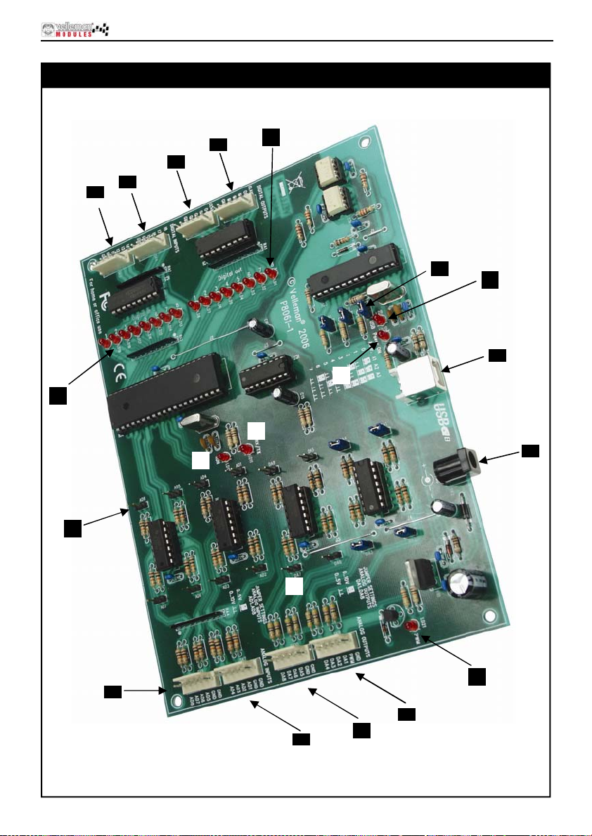
Anschlusspunkte
4
3
Anschlusspunkte
6
5
20
19
12
15
16
13
17
11
18
1
2
8
9
7
10
14
25
Page 26
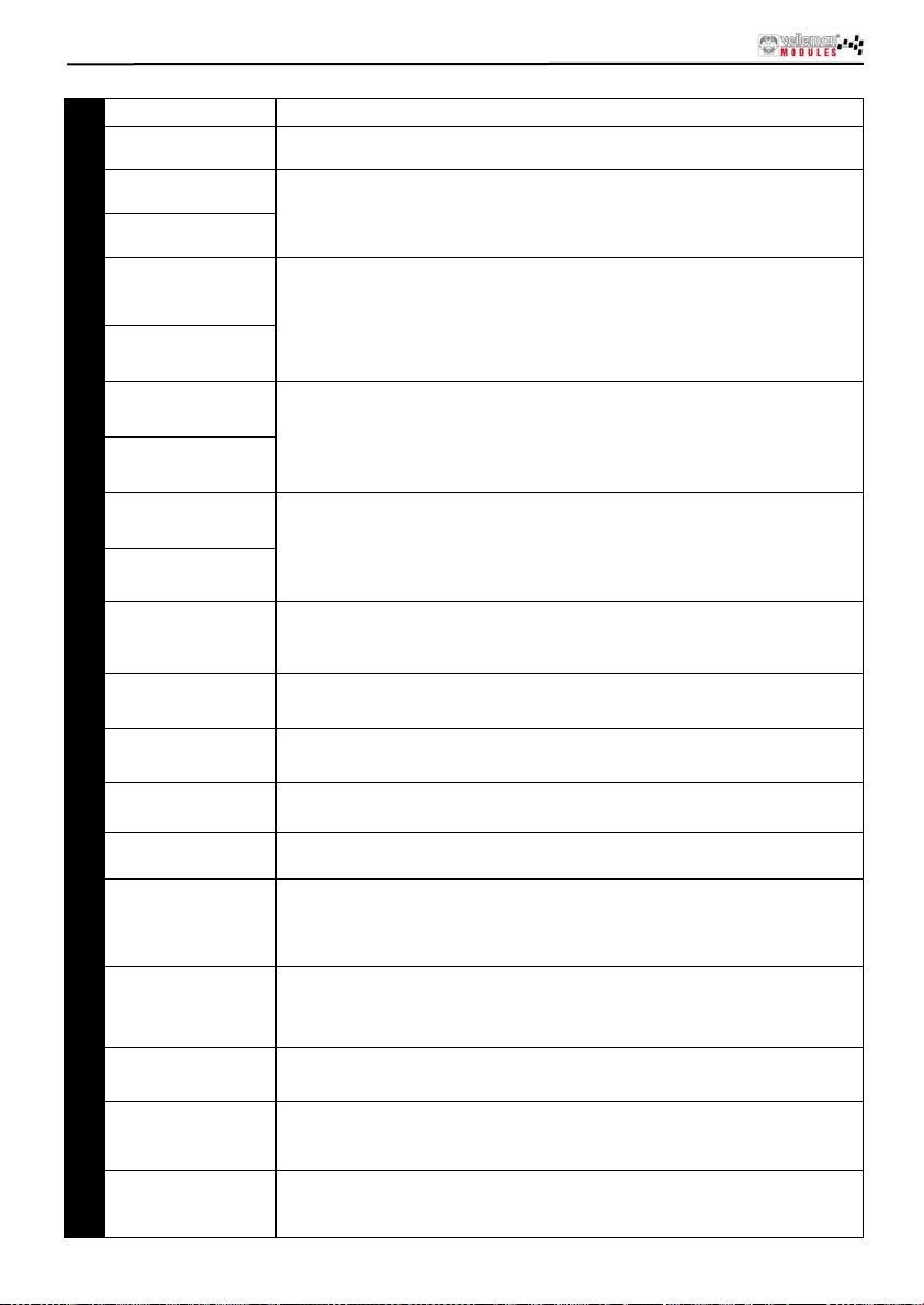
Anschlusspunkte
1 USB-Anschluss Hier können Sie die VM140 mit dem USB-Port eines PC anschließen.
12VDC
2
Digi tale Eingänge 1,
3
2, 3, 4
Digi tale Eingänge 5,
4
6, 7, 8
Digitale Ausgän ge 1,
5
2, 3, 4
Digitale Ausgän ge 5,
6
6, 7, 8
Analoge Eingänge
7
1, 2, 3, 4
Analoge Eingänge
8
5, 6, 7, 8
Analoge Ausgä ng e
9
1, 2, 3, 4
Analoge Ausgä ng e
10
5, 6, 7, 8
Adressierung
11
Jumperauswahl
A/D-
12
Maximalspannung
Maximal e D/A-
13
Ausgangsspannung
PWM-Kontrollleuchte
14
(LED)
CPU “run mode”-
15
LED
CPU RC/TX LED
16
17 “POW E R ON” LED
“USB” LED
18
Digitale
19
Eingangsanzeige
Digitale
20
Ausgangsanzeige
Anschluss der Stro mvers o rgung, hier müsse n Sie einen 12V -nicht-stab ilisierten
Adapter, der mindestens 300mA liefern kann, anschließen.
zur Aktivierung brauchen Sie diese extern "NIEDRIG" (verbinden mit GND) zu
machen.
Diese Ausgänge sind “Open Collector”-Ausgänge, das heißt, wenn Sie aktiviert
werden, werden die Transistoren in IC4 “leiten” und wird eine Verbindung
zwischen GND und d em diesbezü g-lichen Ausgang hergestellt. Die Last, die Sie
steuern wollen, z. B. LED, Rel ais…, muss also eine externe Spannung
bekommen. Der Anschlu ss "CLAMP” v erbinden Sie mit dem "+" -Pol dies er
externen Stromversorgung zum Schutz des Transistorarrays.
Sind Messpunkte, mit denen Sie eine analoge Spannung über PC digitalisieren
und les en können. Die analogen Eingänge erfordern ein e st abile Gleichspannung
zwischen 0 und 5V oder zwischen 0 und 10V. Diese Auswahl können Sie mit den
Jumpern AD1 bis A D8 (siehe Num mer 13) machen. Achtung: wenn Sie eine
Spannung höher als 5 oder 10V an die A/D-Eingänge anlegen, kann die VM140
ernsthaft beschädigt werden ! (IC10/11)
Hier können Sie über die Software die Gleichspannung, die Sie an diese
Ausgänge anlegen können, bestimmen. Abhängig von der Position der Jumper
DA1 bi s DA8 können Sie dies e Spann ung zwi schen 0 un d 5V oder zw ischen 0
und 10V einstellen. An Pin 2 dieses Anschlusses (SK9) finden Sie auch den
PWM-Ausgang. Der PWM-Ausgang ist ein “Open Collector”-Ausgang, dessen
Impulsbreite regelbar ist.
Mit den Jumpern A1, A2 und A3 können Sie jeder angeschlos-senen VM140
eine einzigartige Adresse zuweisen. Es können maxim al 8 Karten angeschlos sen
werden. Wenn Sie nur eine VM140 haben, müssen Sie diese auf Adresse “0”
einstellen.
mit den Jumpern AD1-AD8 können Sie den Spannungs-bereich für die
entsprechenden A/D-Ei ngänge zw ischen 0 bis 5V (geschl ossen) oder 0 bis 10V
(offen) wählen.
mit den DA 1-DA8 Jumpern können Sie den maximalen Spann ungsbereich für
die ent sprechenden D/A-Ausgänge zwischen 0 bis 5V (offen) oder 0 bis 10V
(geschlossen) wählen.
Diese LED le uchtet au f wenn der PWM-Ausgang aktiv ist. Die He llig keit dieser LED
ist analog zu dem Impuls/Pause-Verhältnis.
Leuchtet auf wenn der Pro zessor der VM140 (IC6) korrekt funktionie r t .
Diese LED leucht et auf wenn Daten zwischen dem Pr ozessor und der USBSchnittstelle (IC3) ausgewech s el t werden . Wenn diese LE D ni cht aufleuchtet
während des Kartenbetriebs, dann gibt es einen Fehler im USB-Controller (IC3)
oder in der optischen Tre nnung (IC1 & 2) .
Leuchtet auf wenn es die 5V-Stromversorgung für den USB-Controller gibt.
Achtu ng: Die VM140 wird ver sorgt über US B-Port d es PC
und ist keine Garantie für das Funktionieren des Stromversorgungsteils vom
CPU der VM140 und I/O-Tei l .
Blinkt während d er USB-Ver bindung und leucht et ständig auf wenn ein e
erfol greiche Kom munik at ion zwisc hen dem Chi p in Ihrem PC und d er V M 140
herges te llt wurde.
Diese LEDs erlöschen wenn ein entsprechend er E i ngang "Niedrig" g emacht wir d
(Verbindung des Eingangs mit GND) durch einen externen Kontakt oder einen
externen "Open-Collec tor”-Ausgang.
Diese LEDs leuchten auf wenn ein entspr echend er Ausgang akt iv wird. D as
heißt, wenn eine Ver bindung zw ischen einem Ausgangspin un d GND (“Open
Collector”-Ausgang) he rgestellt wird.
26
Page 27
Software-installation
Software-installation
Nach der Montage der Leiterplatte müssen Sie jetzt die Softwaretreiber und die Beispiele
installieren und die VM140 testen.
Verbinden Sie eine 12V- St r om ver sorgung (nic h t- s t abi lis iertes 12V-Netzgerät ) mit d em V M1 40
Stromversorgungsanschluss (SK2).
Die Kontrollleuchte LED LD12 (RUN) sollte aufleuchten. LD13 bis LD20, da s sind die
Kontrollleuchten der Eingänge, leuchten auf wenn die Eingänge nicht aktiv, "NIEDRIG" sind.
Wenn das in Ordnung ist, verbinden Sie das mitgelieferte USB-Kabel mit dem PC und stellen Sie
eine Verbindung mit dem VM140 USB-Anschluss her .
Zuerst sollte die LED LD10 (POWER) aufleuchten.
Dann sollt e LD 9 (U S B) aufleucht en w en n es t atsächlich ei n e Dat en v erbindung zwis c h en dem PC
und der VM14 0 gibt.
Bevor Si e zu m ersten Male ein e V erbi ndung herstellen, muss den U SB -T reiber des
Mikrocontrollers auf dem PC installiert werden. Der Treiber befindet sich auf der mitgelieferten
CD im Subordner 'USB_driver' de r VM140 Software.
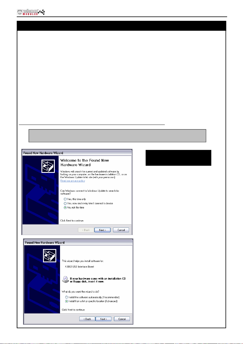
Siehe die Abbildungen des Verlaufes der Treiberinstallation unten
Die VM140 ist die vormontierte Version der K8061. Die Software für die
K8061 ist identisch mit der Software der VM140
Screen sho t s kö n ne n
variieren abhän gig
vom Betriebssyste m.
Schritt 1: Neue Hardware gefun den.
Wählen Sie kein Windows-Update, d.h.
wählen Sie "No, not this time"
Schritt 2: Wählen Sie "Install from a
specific location (advanced)"
27
Page 28
Software-installation
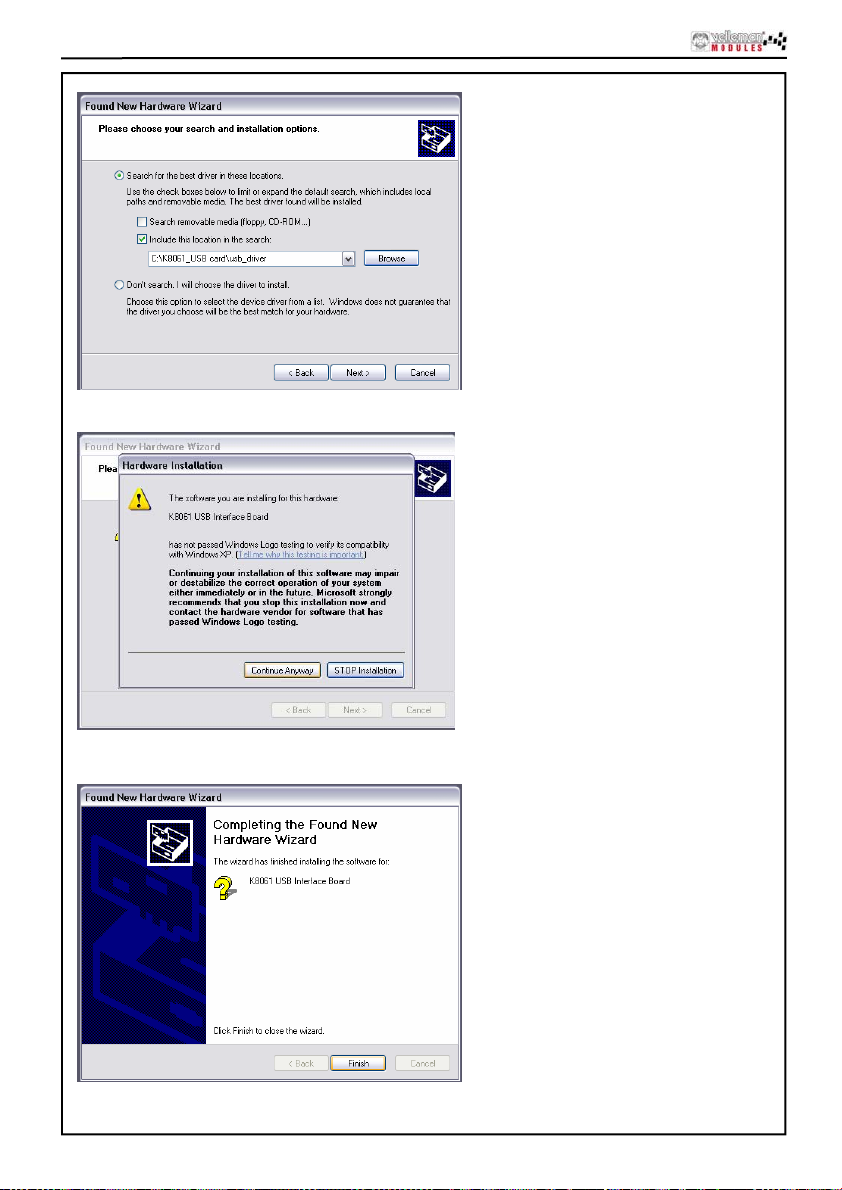
Schritt 3: Durchsuch en Si e den
Treiberordner auf der Festplatt e od er der
mitgelieferten CD.
Wählen Sie den Treiber aus mchpusb.sys
Schritt 4: Wählen Sie "Continue anyway"
zum Bestätigen
28
Schritt 5: Wählen Sie "Finish" zum
Beenden des Verfahrens.
Page 29
Software-installation
Install ation beendet
Im ‘DIAG8061’ Subfolder finden Sie ein Werkzeug um den Betrieb der VM140 zu überprüfen.
Im DEMO8061’ Subfolder steht eine ausführlichere Testapplikation.
Im ‘DLL exam p les’ Subfolder fi nd en S i e den Qu ell encode der Test ap plikation.
Im ‘DOC’ Su bfolder finden S i e m ehr I nformation üb er die Kommunik a tions-DLL der VM 140.
29
Page 30
Anschlussbeispiele
Wie anschließen?
Begrenzungen der technischen Daten, um Schaden zu vermeiden
Überprüfen Sie alle Verbindungen und beachten Sie die
1. Analoger Ausgang:
2. Analoger Eingang:
GND
ANALOGE
AUSGANGSPANNUNG
DAx : +
0 ... 5V
ODER
0 ... 10V
3. Digitaler Ausgang: 4. Digitaler Eingang:
+V
+V :Externe
Stromversorgun
g für Relais,
LED, Lampe.
!
MAX 50VDC
GND
Schalter, ...
ODER
MAX 10V DC !
!
GND
0 ... 5V oder 0 ... 10V
ADx : +
30
Externer Transistor "open
collector" Ausgang
Page 31

Caracterí sticas & Espe cif icaciones
Esta interface consta de 33 entradas/salidas, incluso una salida analógica / digital y + 1 salida MLI.
La conexión al ordenador está aislada de manera galvánica-óptica para evitar dañar el ordenador.
Por tanto, se garantiza más seguridad.
Una DLL - Dynamic Link Library (Biblioteca de vínculos dinámicos) contiene todas las rutinas de
comunicación.
Es posible escribir aplicaciones Windows* personalizadas en Delphi, Visual Basic, C++ Builder,
Micros oft V is u al Basic, Micr os of t VC o l a may oría de las herr ami en tas de desarr oll o de 32 bit que
soport an r uti n as a un a D LL.
FEATURES:
8 entradas analógicas c on un a resolución d e 10 bit : 0… 5 ó 10 V DC / 20k oh m
8 entradas analógicas con una resoluci ón de 8 bit: 0…5V ó 10VCC / 47ohm
8 entradas digitales: compatible con salidas con colector abierto (conexión a GND=0) con
indicador LED incorporado
8 salidas digitales con colector abierto (máx. 50V/100mA) con indicador LED incorporado
una salida PWM de 10 bit: salida de colector abierto de 0 a 100% (máx. 100mA / 40V) con
indicador LED incorporado
puerto USB: compatible USB 1.1 & 2.0
ESPECIFICACIONES :
• consumo de corriento por puerto USB: ± 60mA
• es posible conectar máx. 8 tarjetas al PC
• aliment ac i ón p or ad apt ador: 12VDC / 300 mA (PS1205)
• frecuencia PWM: 15.6kHz
• tiempo d e r eal iz ac i ón es tándar: entr e 21 y 48 ms
• dimensiones de la placa: 195 x 142 x 20mm
EXIGENCIAS MÍNIMAS DEL SISTEMA:
• Pentium CPU con puerto USB libre (1.1 o más reciente)
• Microsoft Windows 2000 o Windows XP*
• lector de CD-ROM y ratón
* ¡Windows XP recomendado!
*Windows XP es una marca registrada de Microsoft Corporation.
31
Page 32
las puntas de conexión
Las puntas de conexión
4
3
5
6
20
19
12
15
16
13
17
11
18
1
2
8
9
7
10
32
14
Page 33
1
Conexión USB Conexión de la VM140 al puerto USB de un ordenador.
2 12VCC
Ent radas digital e s 1,
3
2, 3, 4
Ent radas digital e s 5,
4
6, 7, 8
Salidas digitales 1, 2,
5
3, 4
Salidas digitales 5, 6,
6
7, 8
Entra das an al ó gicas
7
1, 2, 3, 4
Entra das an al ó gicas
8
5, 6, 7, 8
Salidas analógicas
9
1, 2, 3, 4
Salidas analógicas
10
5, 6, 7, 8
Dire c ción de l o s
11
jumper de selección
12
Tensión máx. A/D
13 Tensión máx. N/A
14
LED MLI
LED "run mode" de
15
la unidad central
LED RC/TX de la
16
unidad central
17 LED "POWER ON"
18 LED "USB"
Indicació n entrada
19
digital
Indicació n salida
20
digital
Conexión de la alimentación. Conecte un adaptador no estabilizado de 12V con
una corr ie nte mín. de 300mA.
Para poder activar las entradas, asegúrese de que pasen al nivel bajo
exteriormente (conectar a GND).
Salidas de colector abierto. Si las salidas están activadas, la corriente pasará en
los transistor es del CI4 y una conexión s e establec erá entre GND y la salida en
cuestión. Por tan to, aplique una tensión externa a la carga (LE D, relé …) que
quiere controlar. Conecte la conexión "CLAMP" al polo + de esta alimentación
externa. Todo esto sirve para proteger el "transistor array".
Puntas de medida con las que es p osible digitalizar y leer una tensió n
analógica desde un ordenador. Las entradas analógicas reciben una tensión
CC estabilizada entre 0 y 5V o entre 0 y 10V. Haga la s elección con l os
jumpers de AD1 a AD8 (véase n° 13). ¡Ojo!: ¡Establecer una tensi ón en las
entradas A/D superior a 5 o 10V podría dañar la VM140 (IC10/11)
irrevocablemente!
para determinar la tensión CC que quiere poner en las salidas por el
softwar e. Es posible ajustar esta tensión entre 5 y 5V o entre 0 y 10V seg ún
la posició n de los jumpers d e DA1 a DA8. Encontr ará también la sali da MLI
en el polo 2 d e este conector (SK9 ). La salida MLI es un a salida de colector
abierto con un largo impulso ajustable.
Dirección de los jumper d e selección es posible atribuir una sola dirección a
cada VM140 con los jumpers A1, A 2 y A 3. Conecte hasta 8 tarjetas. Ponga
la dirección en "0" si posee sólo una VM140.
Selecci one el rango de tensión entre 0 y 5V (cerrado) ó 0 y 10V (abierto) con
los jumpers AD1-AD8.
Selecci one el rango de tensión máx. para las salidas A/D corresp ondientes
entre 0 y 5V ( abi erto) o 0 y 10V (cerr ado) con los jump ers DA1-DA8.
Este LED se ilumina si la salida MLI está activa. La lumino-sidad de este
LED es análogo a la relación impulso/pausa.
Se ilumina si la unidad central de la VM140 (IC6) funciona correctamente.
Este LED se il umina durante un intercambi o de datos entre la unid ad central
y el controlado r de interface USB (IC 3). Si el LED no se i lumina mientras la
tarjeta est á funcionando, h ay un error en el cont rolador USB (IC3) o la
separació n óptica (IC1 & 2).
Se ilumin a si est á presente una alimentación de 5V para el controlad or USB.
¡Ojo!: La VM140 está alimentada por el puerto USB del ordenador, lo que no
garantiza el buen funcionamiento de la sección d e al i mentación de CP U y la
sección I/ O de la VM140.
parpadea du rante la conexión USB y se ilumina de manera regular durante
una comunicación lograda ent re el chip USB d el ordenador y la VM140.
Estos LEDs se apagan si una entr ada correspondiente pasa al nivel bajo
(conexión de la entrada a GND) p or un contacto externo o una salida de
colector abi ert o externo.
Estos LEDs se iluminan si l a ent rada corresp ondiente está activa, es decir
durante una conexión en tre un polo d e salida y GND ( salida de colector
abierto).
las puntas de conexión
33
Page 34
Instalación del software
Instalación del software
Después de h aber montad o el CI puede instalar los dri ver s d el s oftware y los ejem pl os y c omprobar
la VM140.
Conect e una alimentaci ón de 12V (adaptad or 12V no estabiliz ad o) al con ect or d e ali m ent ac ión
VM140 (SK2).
Tanto el LED de control LD12 (RUN) como los LEDs de LD13 a LD20 (son los LEDs de control
de las entr adas que se ilumi n arán s i las entradas no están activas en el niv el “ BA J O ”) se
iluminarán.
Luego, conecte el cable USB (incl.) al ordenador y haga la conexión con el conector USB VM140.
LD10 (POWER) se iluminará lo primero.
Luego , LD9 (USB ) se ilumina rá si hay una conexión de datos entre el ordenador y la VM140.
Al hacer la c onexión por pri m era vez , ins tale primer o el dr iver USB del micr oc on trolador en el
ordenad or . Es te driver se encu ent r a en el C D (i nc l.) en el subdirect orio ‘USB_dr i ver’ del softwar e
de la VM140.
Véase las siguientes figuras que ilustran el desarrollo de la instalación del driver
La VM140 es la versión pre mon t ad a de l a K8061. El soft war e de la K8061
es el mismo que el de la VM140
Las capturas de pantalla pueden
variar según el sistema operativo.
34
Paso 1: detección de nuevo hardware.
No seleccione una actualización de
windows, pulse "No, not this time".
Paso 2: Seleccione "Install from a
specific location (Advanced)"
Page 35
Instalación del software
Paso 3: Hojee el fic h ero del driver en el
disco dur o o el CD inc l ui do.
Seleccione el driver mchpusb.sys
Paso 4: Seleccione "Continue
Anyway" para confirmar.
Paso 5: Seleccione "Finish" para
termin ar el procedimient o.
35
Page 36
Instalación del software
Instalación terminada
En el subdirectorio "DIAG8061" encontrará un fichero "utility" para verificar el funcionamiento de
la K8061.
Una aplic ac i ón de pr u eb a m ás d etallada está en el su bdi rectorio "DE MO 8 06 1" .
En el subdir ectorio ‘DLL ex am p l es’ es tá un código de fu ent e de la aplicaci ón d e prueba
En el subdirectorio ‘DOC’ está la explicación sobre la DLL comunicación de la K8061
36
Page 37
¿Cómo conectar?
Ejemplos de conexión
Verifique todas las conexiones y respete las limitaciones de las
especificaciones para evitar cualquier daño.
1. Salida analó gica:
2. Entrada analógica:
GND
TENSIÓN DE SALIDA
ANALÓGICA
DAx : +
0 ... 5V
O
0 ... 10V
3. Entrada digital: 4. Salida digital:
+V
+V :Alimentación
externa para relé,
LED, lámpara.
!
MAX 50VDC
GND
Interruptor, ...
MAX 10V DC !
!
GND
0 ... 5V o 0 ... 10V
ADx : +
O
Salida transistor externo
"colector abierto"
37
Page 38
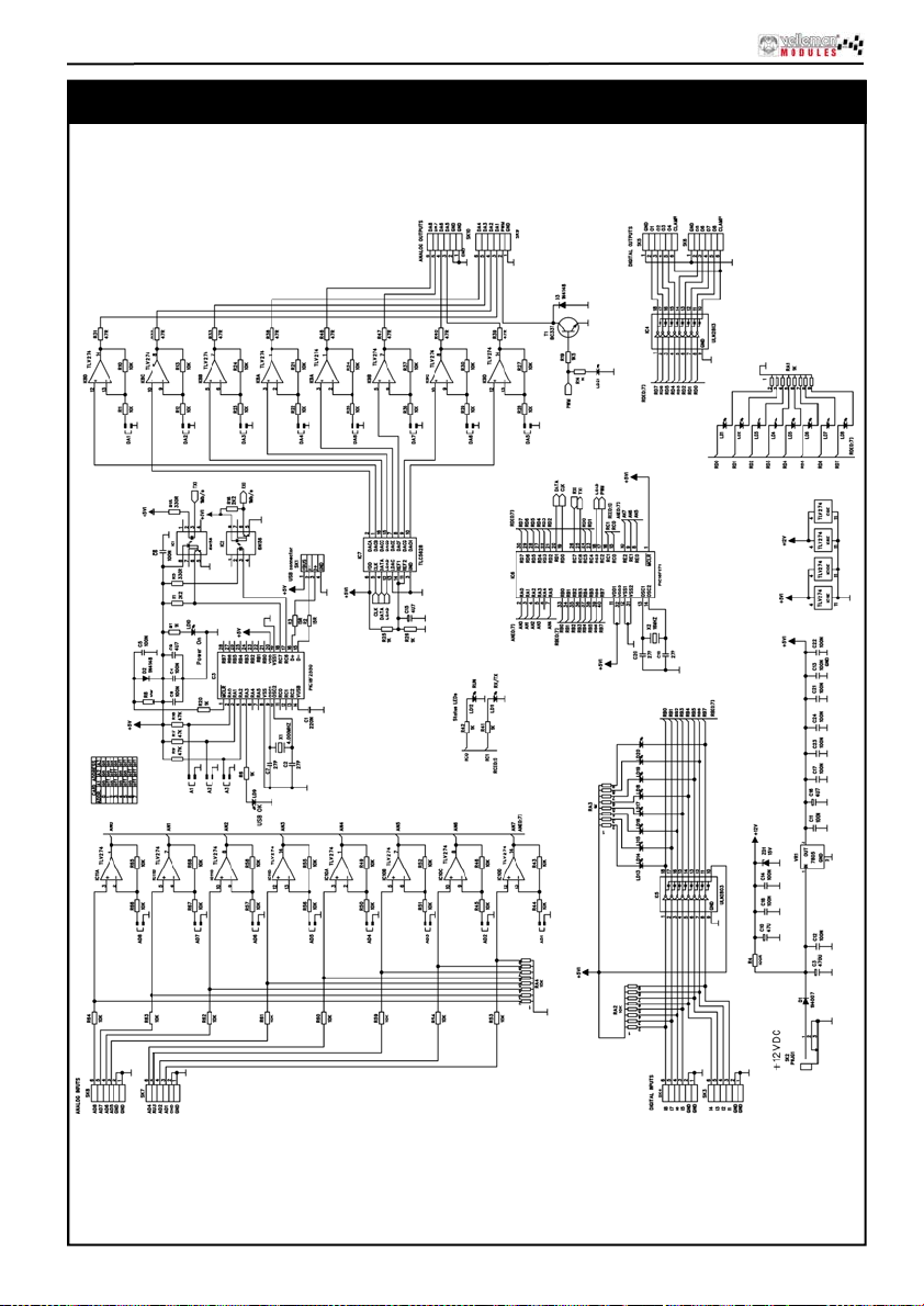
Schematic diagram
Schem ati c dia gr am
38
Page 39
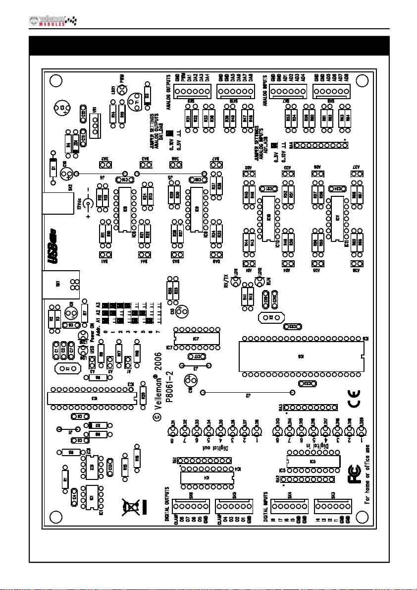
PCB layout.
PCB
39
Page 40
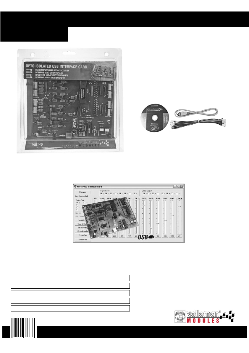
VM140
USER MANUAL
Extended USB interface board
Extended USB interface board
Extended USB interface board
Belgium [Head office] Velleman Components +32(0)9 384 36 11
France Velleman Electronique +33 320 15 86 15
Netherlands Velleman Components +31(0)76 514 7563
USA Velleman Inc. +1(817)284 7785
Spain Velleman Components +34 954 126800
5 410329 373436
Modifications and typographical errors reserved - © Velleman Components nv - HVM140G - 2007 - ED1
 Loading...