

Page 1
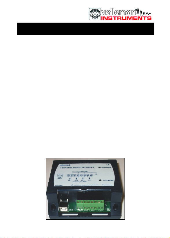
4 channel recorder / logger
Hardware:
þ USB connected and powered.
þ Four DC coupled input channels.
þ Input resistance 1Mohm.
þ Maximum samples per second : 100
þ Four input ranges, 3V / 6V / 15V and 30V.
þ Sensitivity 10mV.
þ Accuracy ±3% of full scale.
þ Maximum input 30Vdc.
þ Power and recording/diagnostic LED indication on unit.
þ Sample rate : 100S/s
Software:
• Analogue trace or digital DVM readout.
• 4 simultaneous channels recording.
• Minimum / maximum sample hold function for DVM.
• From 1 sec to 1000 sec per division.
• Storage and recall of screens (full colour) or data.
• Automatic recording option for long time recordings.
• On screen markers for time and voltage.
• DLL included for own development.
PCS10
HPCS10TD-1
Page 2

2
VELLEMAN Components NV
Legen Heirweg 33
9890 Gavere
Belgium Europe
www.velleman.be
Page 3

Declaration of Conformity
We, Manufacturer
Velleman Components
Legen Heirweg 33
9890 Gavere
Belgium
declare that the product
PCS10 Recorder / logger
if used according the instructions included with the unit meet the directives
in accordance with 89/336/EEC -EMC Directive
and
EN 55022 Limits and methods of measurement of radio interference
EN
50082-1
FCC Part
15
characteristics of information technology equipment
(CISPR22 limits)
Electromagnetic Compatibility - Generic immunity standard
Part B Unintentional radiators
For the manufacturer
Date: 28/10/2002
Signature: _____________________________
Name: Stephan Santens
R&D manager
Page 4
C...
PARTSLIST
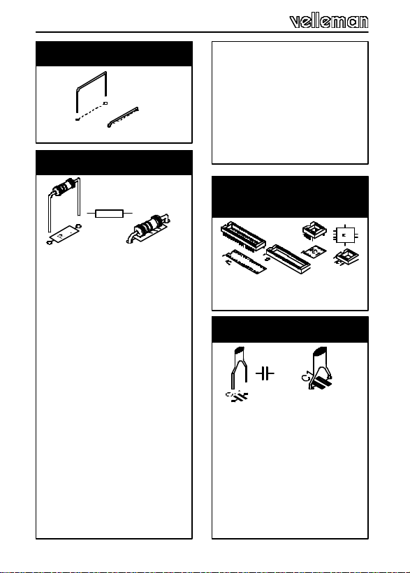
1. Jumper
q J
2. Resistors
R...
q R1 : 1K5 (1-5 -2-B)
q R2 : 3K (3-0 -0-1-1)
q R3 : 6K8 (6-8 -0-1-1)
q R4 : 27K (2-7 -0-2-1)
q R5 : 91K (9-1 -0-2-1)
q R6 : 1M (1-0 -0-4-1)
q R7 : 91K (9-1 -0-2-1)
q R8 : 1M (1-0 -0-4-1)
q R9 : 27K (2-7 -0-2-1)
q R10 : 470E (4-7 -1-B)
q R11 : 6K8 (6-8 -0-1-1)
q R12 : 27K (2-7 -0-2-1)
q R13 : 27K (2-7 -0-2-1)
q R14 : 91K (9-1 -0-2-1)
q R15 : 91K (9-1 -0-2-1)
q R16 : 1M (1-0 -0-4-1)
q R17 : 1M (1-0 -0-4-1)
q R18 : 1K5 (1-5 -2-B)
q R19 : 27K (2-7 -0-2-1)
q R20 : 6K8 (6-8 -0-1-1)
q R21 : 3K (3-0 -0-1-1)
q R22 : 3K (3-0 -0-1-1)
q R23 : 1K5 (1-5 -2-B)
4
q R24 : 27K (2-7 -0-2-1)
q R25 : 1K5 (1-5 -2-B)
q R26 : 27K (2-7 -0-2-1)
q R27 : 6K8 (6-8 -0-1-1)
q R28 : 3K (3-0 -0-1- 1)
q R29 : 27K (2-7 -0-2-1)
q R30 : 1K5 (1-5 -2-B)
q R31 : 470E (4-7 -1-B)
q R32 : 1K5 (1-5 -2-B)
3. IC sockets.
q IC1 : 28p
q IC2 : 14p
4. Ceramic Capacitors
q C1 : 220nF (224, 0.22)
q C2 : 33pF (33)
q C3 : 33pF (33)
q C4 : 100nF (104, 0.1, u1)
q C6 : 100nF (104, 0.1, u1)
q C7 : 100nF (104, 0.1, u1)
q C8 : 100nF (104, 0.1, u1)
q C9 : 100nF (104, 0.1, u1)
q C10 : 100nF (104, 0.1, u1)
q C11 : 100nF (104, 0.1, u1)
Page 5
PIN 1
C...
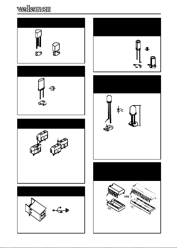
5. Zenerdiode
q ZD1 :
6. Quartz crystal
q X1 : 6MHz
X...
7. Screw connectors
q J1 : 2P (CH1)
q J2 : 2P (CH2)
q J3 : 2P (CH3)
q J4 : 2P (CH4)
8. USB connector
q J5 : USB B90
9. Electrolytic capacitors.
q C5 : 4,7µF/ 50V
10. LED’s.
LD1
CATHODE
‘Red’ => Recording
30mm
q LD1 :
3mm
q LD2 : 3mm
‘Green’ => Power ON
11. IC’s.
1
q IC1 : VK8047
Programmed PIC16C745-IP !
q IC2 : TLV274IP
5
Page 6
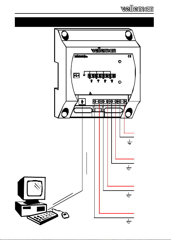
Connections
®
INSTRUMENTS
4 CHANNEL SIGNAL RECORDER
Connected to PC's GND
USB
INPUT
CH 1 CH 2 CH 3 CH 4
Signal input max. 30VDC
* See manual for safety and operating instructions. - Designed in Europe
PCS10 / K8047
USB CABLE - A MALE TO B MALE
USB POWER
RECORDING
+
Signal 4
+
Signal 3
+
Signal 2
6
+
Signal 1
Page 7
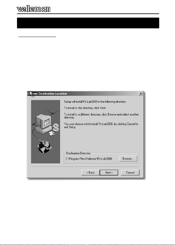
Software installation and test
A. Installation :
• Install the software. If the necessary software is not inluded or
if you want to check for updates, you can always download it
for free from our Velleman Website www.velleman.be
• An installation wizard will guide you trough the installation
procedure.
• By default the software is installed in the folder :
‘C:\Program Files\Velleman\Pc-Lab2000’
Fig 1.0
7
Page 8
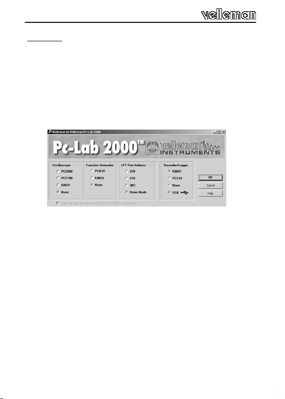
B. Test :
• Hook-up a USB cable between a free port of your computer
and the K8047 (see page 8.)
• Connect a 9V battery to one of the signal inputs (CH1, CH2,
CH3 or CH4), respect the polarity (+ and -)!
• Start the PC-Lab2000 software and select the appropriate
device (K8047).
Fig 2.0
• Select 15 or 30V range.
• Press the run button.
The unit is ready for use when a signal appears on the
screen.
G Other information concerning this unit
can be found on the CD.
8
Page 9
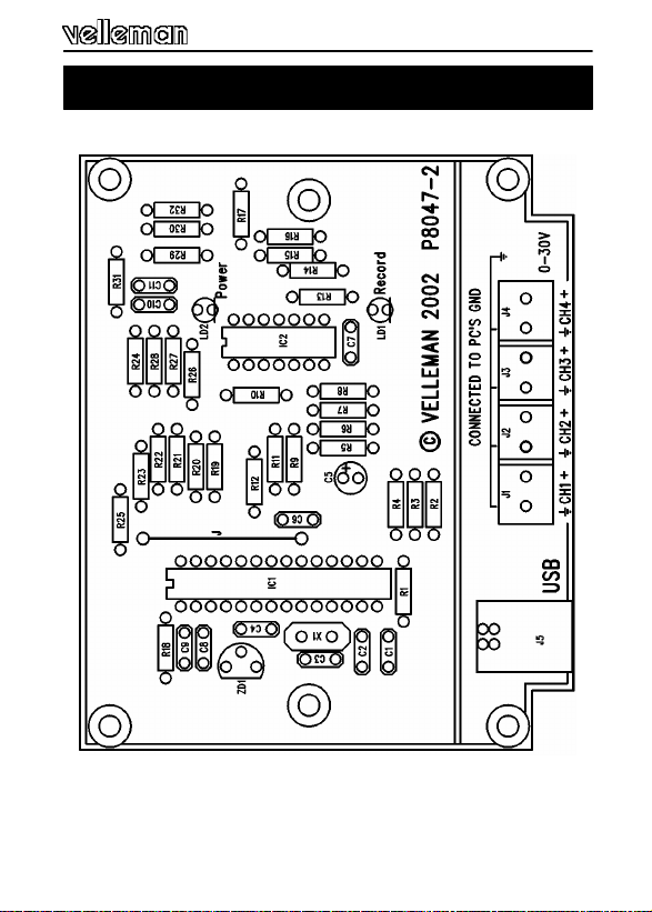
PCB layout.
9
Page 10
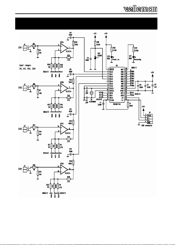
Schematic diagram
15. Schematic diagram.
10
Page 11

Revision Notes:
11
Page 12

Modifications and typographical errors reserved
© Velleman Components nv.
HPCS10TD - 2003 - ED1
 Loading...