

Velleman Instruments PCG10, K8016 Reference Manual
PC Generator
PCG10 / K8016
CHECK THE Pc- Lab2000
FOR SOFTWARE INSTALLATION
TM
GETTING STARTED GUIDE
RReeffeerreennccee MMaannuuaall

PCG10 / K8016
VELLEMAN Instruments is a division of
VELLEMAN Components NV
Legen Heirweg 33
9890 Gavere
Belgium
Support & updates : http://www.Velleman.be
Velleman Instruments
HPCG10_GB- 2001– 1
2

PCG10 / K8016
FCC information for the USA
This equipment has been tested and found to comply with the limits for a
Class B digital device, pursuant to Part 15 of the FCC Rules. These limits are
designed to provide reasonable protection against harmful interference in a
residential installation. This equipment generates, uses and can radiate
radio frequency energy and, if not installed and used in accordance with the
instructions, may cause harmful interference to radio communications.
However, there is no guarantee that interference will not occur in a particular
installation. If this equipment does cause harmful interference to radio or
television reception, which can be determined by turning the equipment off
and on, the user is encouraged to try to correct the interference by one or more
of the following measures:
• Reorient or relocate the receiving antenna.
• Increase the separation between the equipment and receiver.
• Connect the equipment into an outlet on a circuit different from that to
which the receiver is connected.
• Consult the dealer or an experienced radio/TV technician for help.
Important
This equipment was tested for FCC compliance under conditions that include
the use of shielded test leads between it and the peripherals. It is important
that you use shielded cables and connectors to reduce the possibility of
causing Radio and Television interference.
Shielded probes, suitable for the PCG10 unit can be obtained from the
authorized Velleman dealer.
If the user modifies the PCG10 unit or its connections in any way, and these
modifications are not approved by Velleman, the FCC may withdraw the user’s
right to operate the equipment.
The following booklet prepared by the Federal Communications Commission
may be of help: “How to identify and Resolve Radio-TV Interference problems”.
This booklet is available from the US Government Printing Office, Washington,
DC20402 Stock No. 044-000-00345-4.
3

PCG10 / K8016
Features:
þ Frequency range from 0.01Hz to 1 MHz.
þ Crystal-based stability.
þ Optically isolated from the PC.
þ Low sine wave distortion.
þ TTL level synchronization output.
þ Stores up to 32K of waveform points.
þ Standard waveforms: Sine, Square, and Triangle.
þ Predefined library waveforms included: Noise, Sweep,...
þ Extended bode plot option together with PC scope.
þ You can create your own waveforms with the integrated signal wave editor.
þ Can be chained with Velleman PC oscilloscopes to the same PC printer
port (LPT1, 2 or 3).
Specifications:
• Power supply: Standard 12V DC adapter,800mA (PS1208).
• Direct Digital wave synthesis (DDS), 32K wave table.
• Frequency setting resolution: 0.01%.
• Amplitude range: 100mVpp to 10Vpp @ 600 Ohm load.
• Amplitude resolution: 0.4% of full scale.
• Offset: from 0 to -5V or +5V max. (resolution 0.4% of full scale).
• Vertical resolution: 8 bits (0.4% of full scale).
• Maximum sample rate: 32MHz.
• Typical sine wave distortion (THD): < 0.08% (with 0dB and <100 Khz, 1v
RMS)
• Output impedance: 50 Ohm.
• Dimensions (wxdxh): 235x165x47mm (9.3”x6.5”x1.9”).
system requirements
• IBM compatible PC
• Windows 95, 98, ME, (Win2000 or NT possible)
• SVGA display card (min. 800x600)
• mouse
• free printer port LPT1, LPT2 or LPT3
• CD Rom player
Options
• Soft carry case: GIP
4

PCG10 / K8016
SAFETY and WARNINGS
Symbols displayed on the unit
!
Important safety information, see user manual.
The PCG10 / K8016 is optically isolated from the PC, but even then
it is advisable to use only on safe devices.
⇒ Measurements should be avoided in case of polluted or very humid air.
Before making measurements and for safety reasons, it is important to know
some information about the measured unit.
Safe devices are:
• Battery operated equipment
• Equipment supplied via a transformer or adapter.
Unsafe devices are:
• Equipment directly connected to mains (e.g. old TV sets)
• Equipment that contains components that are directly connected to mains
• It is advisable, when measuring on above equipment, to use a isolation
transformer.
Use of unsafe devices can result in damage to the
generator circuit!
5
PCG10 / K8016
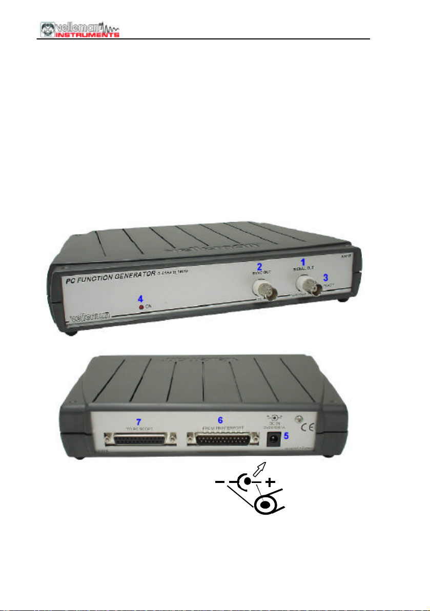
CONNECTIONS
Survey of the connections and controls
1.BNC signal output connector (50ohm max 10Vpp)
2.BNC external trigger output (TTL level)
3.Output ready LED (indicates if output signal is present)
4.Power indication LED (software driven)
5.Adapter connection (observe the polarity!)
6.Parallel port connector to computer
7.Parallel pass through connector for optional PC scope (PCS500, PCS100 /
K8031)
The unit is connected to the printer port
(LPT) of the computer, using a standard 25P male/female parallel cable.
6

PCG10 / K8016
Connection
Connect the unit to the printer port LPT1, LPT2 or LPT3.
A Velleman PC scope can be connected to the “To PC Scope” connector.
To select the LPT port address click Hardware Setup on Options menu of the
oscilloscope window, or run Pc-Lab2000 software.
Connect the mains voltage DC adapter to the unit : 12VDC / 800mA. (pin =
positive).
MATTENTION: Only use adapter with correct voltage otherwise the unit could
be damaged.
Using a wrong power supply could blow the internal fuse. The fuse is
soldered onto the PCB, please contact an experienced service center, to
replace the fuse. The best way is to cut the leads of the fuse , and to solder a
new (1A PICO) fuse onto the old leads.
After starting the software (see also getting started manual), the LED on the
front panel should lid.
7
 Loading...