

Page 1

DVM8264 – 3 ½ DIGITAL MULTIMETER – 30 RANGES
1. Introduction & Features
To all residents of the European Union
Important environmental information about this product
This symbol on the device or the package indicates that disposal of the device after its lifecycle could harm
the environment.
Do not dispose of the unit (or batteries) as unsorted municipal waste; it should be taken to a specialised
company for recycling.
This device should be returned to your distributor or to a local recycling service.
Respect the local environmental rules.
If in doubt, contact your local waste disposal authorities.
Thank you for buying the DVM8264! Please read the manual thoroughly before bringing this device into service. If the
device was damaged in transit, don't install or use it and contact your dealer.
2. Precautionary Safety Measures
• Measurement category III is for measurements performed in the building installation.
• Measurement category II is for measurements performed on circuits directly connected to the low-voltage
installation.
• Measurement category I is for measurements performed on circuits not directly connected to the mains.
• When using this multimeter, the user must observe all normal safety rules concerning:
o protection against the dangers of electric current.
o protection of the multimeter against misuse.
• For your own safety, only use the test probes supplied with the instrument. Before use, check that they are in
good condition.
• If the meter is used near noise-generating equipment, be aware that the display may become unstable or may
indicate large errors.
• Do not use the meter or test leads if they look damaged.
• Use the meter only as specified in this manual; otherwise, the protection provided by the meter may be impaired.
• Use extreme caution when working around bare conductors or bus bars.
• Do not operate the meter around explosive gas, vapour or dust.
• Verify the meter's operation by measuring a known voltage. Do not use the meter if it operates abnormally.
Protection may be impaired. When in doubt, have the meter serviced.
• Use the proper terminals, function and range for your measurements.
• When the range of the value to be measured is unknown, check that the range initially set on the multimeter is the
highest possible or, wherever possible, choose the auto-ranging mode.
• To avoid damages to the instrument, do not exceed the maximum limits of the input values shown in the technical
specification tables.
• When the multimeter is linked to measurement circuits, do not touch unused terminals.
• Caution when working with voltages above 60VDC or 30VAC rms. Such voltages pose a shock hazard.
• When using the probes, keep your fingers behind the finger guards.
• When making connections, connect the common test lead before connecting the live test lead; when
disconnecting, disconnect the live test lead before disconnecting the common test lead.
• Before changing functions, disconnect the test leads from the circuit under test.
• For all DC functions, including manual or auto-ranging, to avoid the risk of shock due to possible improper
reading, verify the presence of any AC voltages by first using the AC function. Then select a DC voltage range
equal to or greater than the AC range.
• Disconnect circuit power and discharge all high-voltage capacitors before testing resistance, continuity, diodes or
capacitance.
DVM8264 - 1 - VELLEMAN
Page 2
• Never perform resistance or continuity measurements on live circuits.
• Before measuring current, check the meter's fuse and turn off power to the circuit before connecting the meter to
the circuit.
• In TV repair work or when carrying out measurements on power switching circuits, remember that high-amplitude
voltage pulses at the test points can damage the multimeter. Use of a TV filter will attenuate any such pulses.
• Use the 9V battery, properly installed in the meter's battery case, to power the meter.
• Replace the battery as soon as the battery indicator ( ) appears. With a low battery, the meter might produce
false readings that can lead to electric shock and personal injury.
• Do not measure voltages above 600V in Category III or 1000V in Category II installations.
• Do not operate the meter with the case (or part of the case) removed.
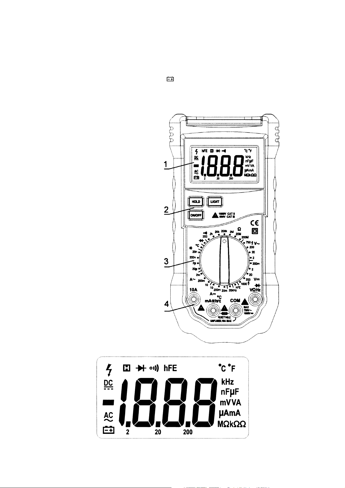
3. Description
a. Front Panel (fig.1)
1. LCD display
2. Keypad
3. Rotary switch
4. Terminals
b. LCD Display (fig. 2)
DVM8264 - 2 - VELLEMAN
Page 3
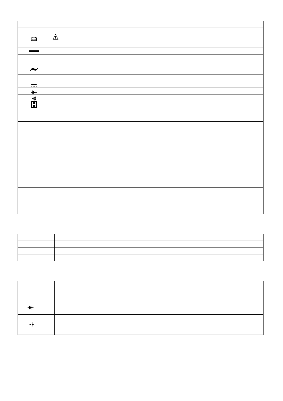
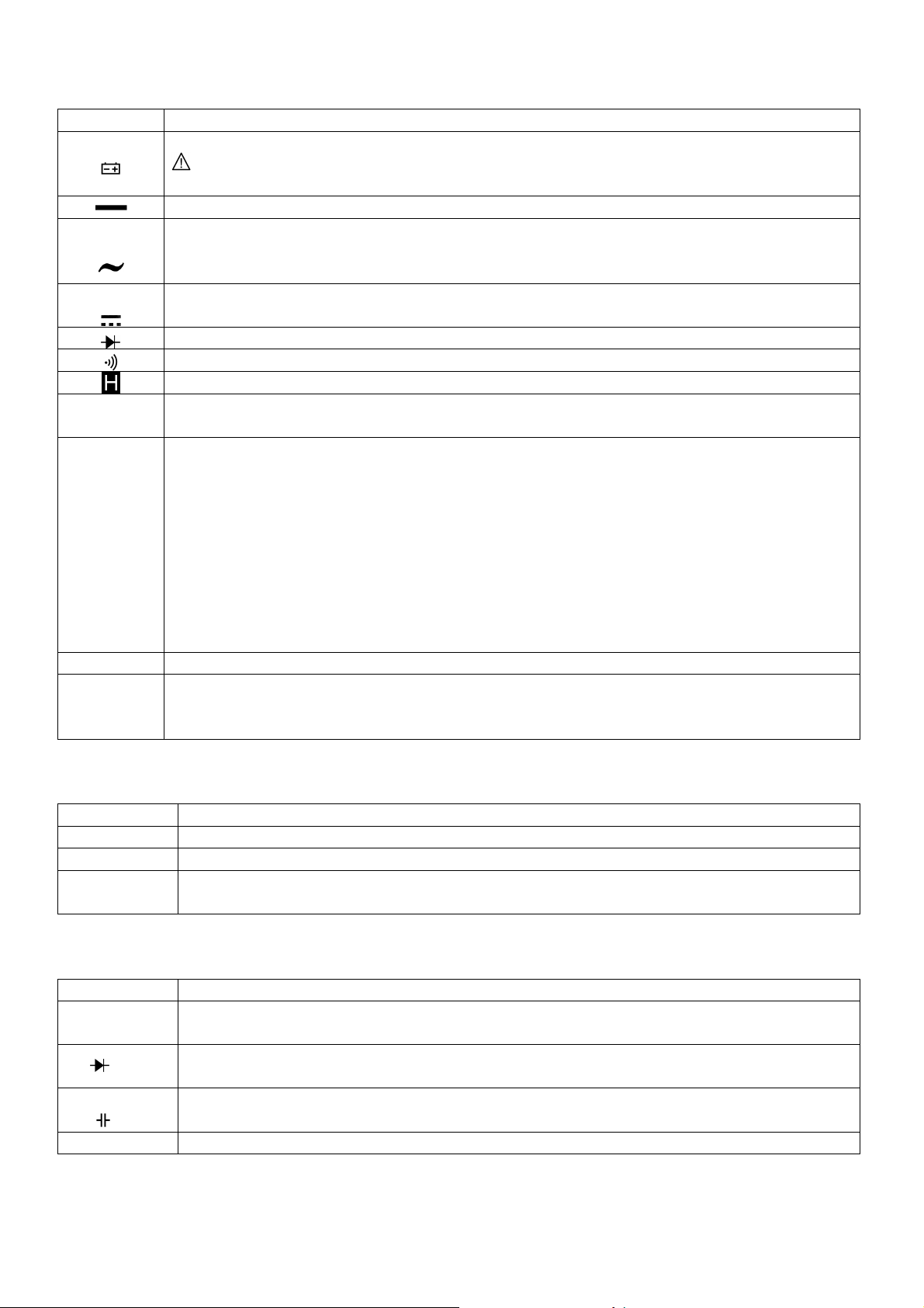
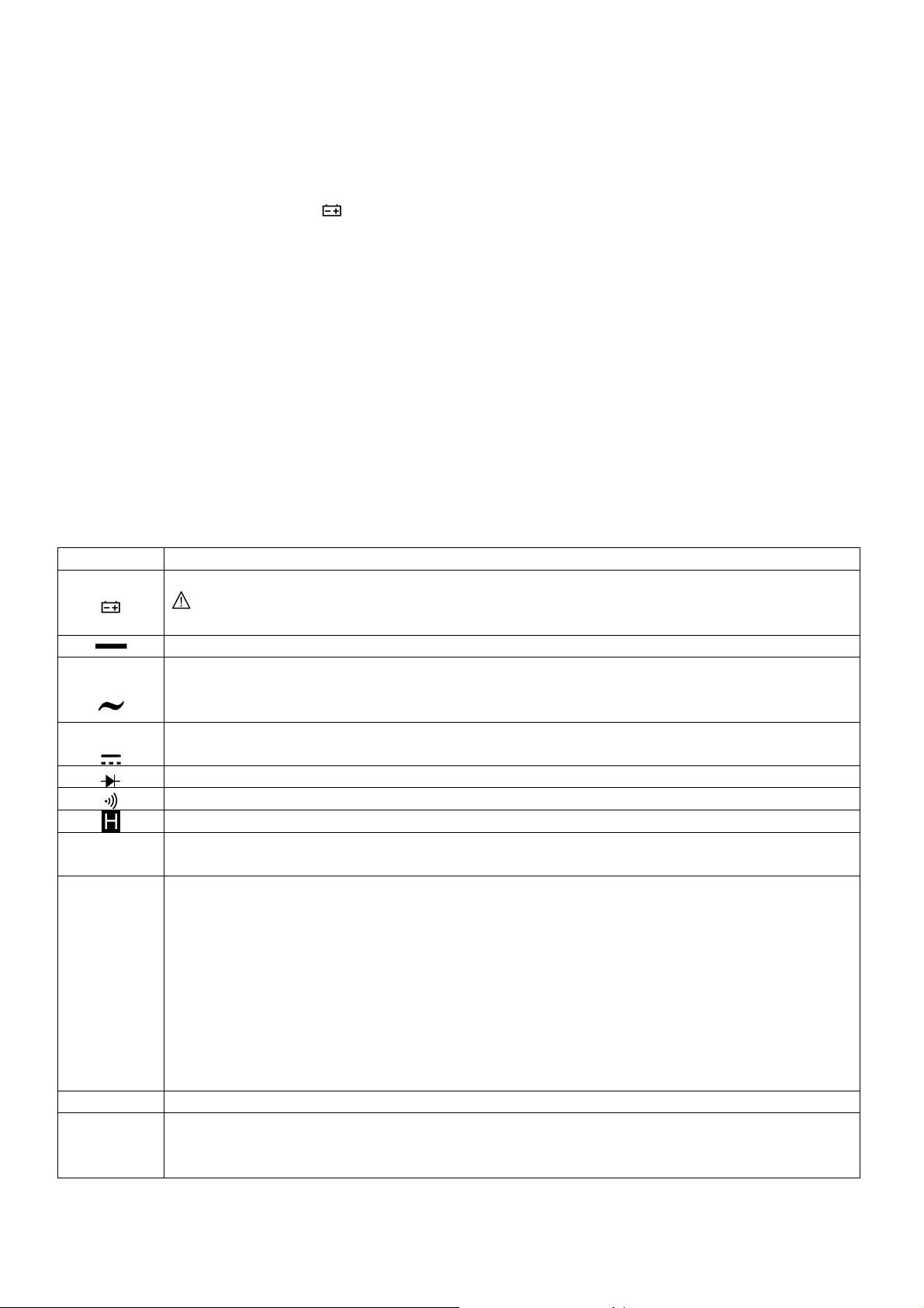
Symbol Description
The battery is low.
Warning: To avoid false readings, which could lead to possible electric shocks or personal injury,
replace the battery as soon as the battery indicator appears.
Indicates negative readings.
AC
DC
Indicator for AC voltage or current.
AC voltage and current are displayed as the average of the absolute value of the input, calibrated to
indicate the equipment rms value of a sine wave.
Indicator for DC voltage or current.
°C or °F
The meter is in diode test mode.
The meter is in continuity check mode.
The meter is in data hold mode.
°C: Celsius scale or the unit of temperature.
°F: Fahrenheit scale.
V: Volts or the unit of voltage.
V, mV
A, mA, µA
Ω, kΩ, MΩ
mV: Millivolt or 1 x 10⁻³ or 0.001 volts.
A: Amperes (amps) or the unit of current.
mA: Millamp or 1 x 10⁻³ or 0.001 amps.
µA: Microamp or 1 x 10⁻⁶ or 0.000001 amps.
Ω: Ohm or the unit of resistance.
mΩ: Kilohm or 1 x 10³ or 1000 ohms.
MΩ: Megohm or 1 x 10⁶ or 1,000,000 ohms.
kHz Kilohertz or 1 x 10³ or 1000 Hertz.
F: Farad or the unit of capacitance.
µF, nF
µF: Microfarad or 1 x 10⁻⁶ or 0.000001 farads.
nF: Nanofarad or 1 x 10⁻⁹ or 0.000000001 farads.
c. The Keypad
Key Function
ON/OFF Turn the meter on or off.
HOLD Press HOLD to enter and exit the data hold mode.
LIGHT Press LIGHT to turn the backlight on. After about 5 seconds, the backlight goes off automatically.
d. The Terminals
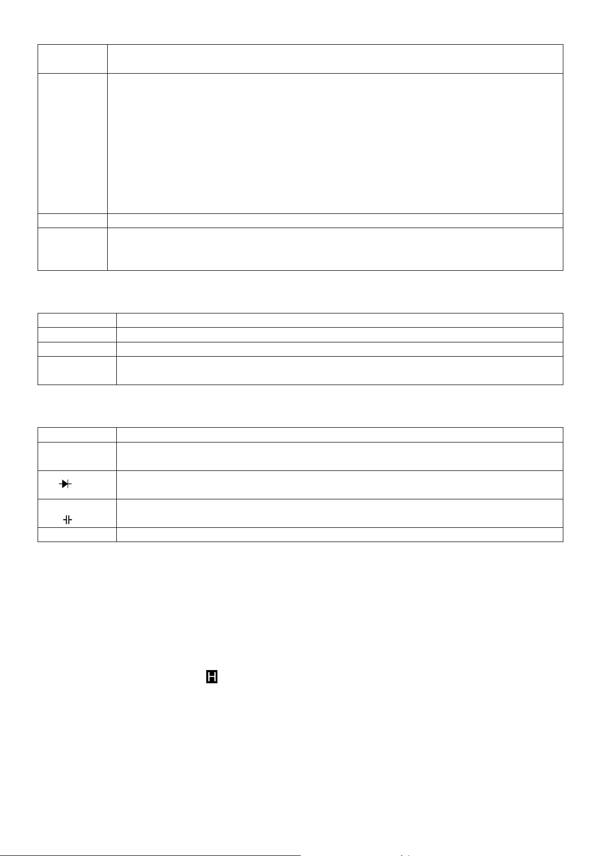
Terminal Description
COM
VΩHz
°CmA
hFE
Return terminal for all measurements (receiving the black test lead or the “COM” plug of the
special multi-function socket).
Input for voltage, resistance, frequency, diode and continuity measurements (receiving the red test
lead).
Input for capacitance, temperature, hFE and 0.001mA to 200mA current measurements (receiving
the red test lead or the “+” plug of the special multi-function socket).
10A Input for 200mA to 10A current measurements (receiving the red test lead).
DVM8264 - 3 - VELLEMAN
Page 4
4. Operating Instructions
To avoid electrical shock and/or damage to the instrument, do not attempt
to measure
To avoid electrical shock and/or damage to the instrument,
disconnect the circuit power and
a. Data Hold Mode
The data hold function makes the meter stop updating the display. This function can be cancelled by changing the
measurement mode or by pushing the HOLD key again.
To enter the mode:
1. Press the HOLD key. appears on the display.
2. A second short press returns the meter to the normal mode.
b. Battery Saver
Turn on the meter. The meter turns off automatically after approximately 30 minutes.
c. AC and DC Voltage Measurement
Voltage is the difference in electrical potential between two points. The polarity of AC voltage varies over time; the
polarity of DC voltage is constant. The meter’s DC voltage ranges are 200mV, 2V, 20V, 200V and 1000V; AC
voltage ranges are 2V, 20V, 200V and 750V.
To measure AC or DC voltages:
NOTE: The displayed values may be unstable especially at 200mVDC and 2VDC ranges even though you do not
d. Resistance Measurement
voltages exceeding 1000VDC / 750VAC rms.
To avoid electrical shock and/or damage to the instrument, do not apply more 1000VDC or
750VAC rms between the COM terminal and the earth ground.
1. Set the rotary switch to the proper range.
2. Connect the black and red test leads to the COM and V terminals respectively.
3. Connect the test leads to the circuit being measured.
4. Read the displayed value. The polarity of the red test lead connection will be indicated when making a DC
measurement.
put the test leads into the input terminals. If an erroneous reading is suspected, short the V and the COM
terminal and make sure the LCD displays a zero value.
Resistance is an opposition to current flow. The unit of resistance is ohm (Ω). The meter’s resistance ranges are
200Ω, 2kΩ, 20kΩ, 200kΩ, 2MΩ, 20MΩ and 200MΩ.
To measure resistance:
DVM8264 - 4 - VELLEMAN
discharge all high-voltage capacitors before measuring resistance.
1. Set the rotary switch to the proper range.
2. Connect the black and red test leads to the COM and Ω terminals respectively.
3. Connect the test leads to the circuit being measured and read the displayed value.
Page 5
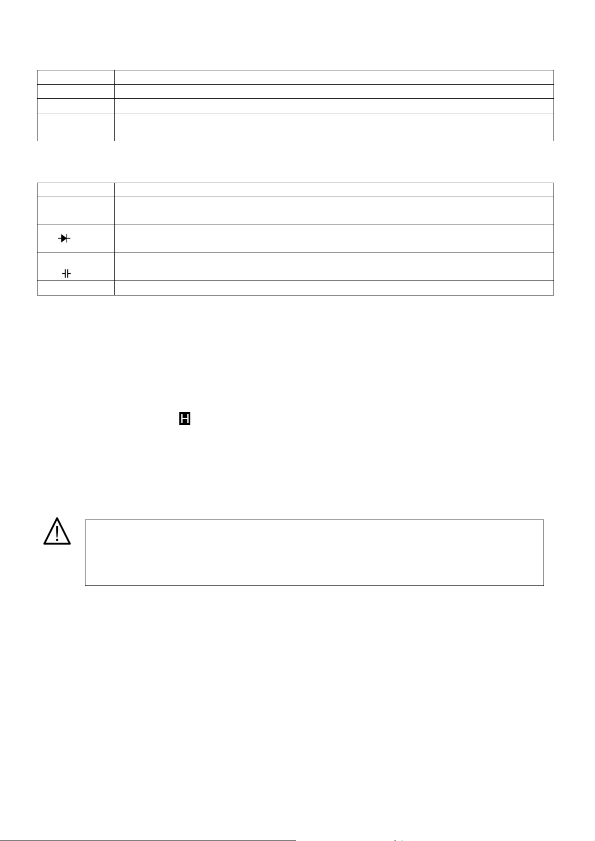
e. Diode Test
To avoid
electrical shock and/or damage to the instrument,
disconnect the circuit power and
To avoid electrical shock and/or damage to the instrument,
disconnect the circuit power and
To avoid electrical shock and/or damage to the instrument,
disconnect the circuit power and
discharge all high-voltage capacitors before testing diodes.
Use the diode test to check diodes and other semiconductor devices. The diode test sends a current through the
semiconductor junction and measures the voltage drop across the junction. A good silicon junction drops between
0.5V and 0.8V.
To test a diode out of a circuit:
1. Set the rotary switch to range.
2. Connect the black and red test leads to the COM and terminals respectively.
3. For forward-bias readings on any semiconductor component, place the red test lead on the component’s
anode and place the black test lead on the cathode.
4. The meter will show the approximate forward voltage of the diode. If the test lead connection is reversed,
only figure “1” is displayed.
In a circuit, a good diode should still produce a forward bias reading of 0.5V to 0.8V. However, the reverse-bias
reading can vary depending on the resistance of other pathways between the probe tips.
f. Continuity Check
discharge all high-voltage capacitors before testing the continuity.
Continuity is a complete path for current flow. The beeper sounds if a circuit is complete.
To test for continuity:
1. Set the rotary switch to range.
2. Connect the black and red test lead to the COM and Ω terminals respectively.
3. Connect the test leads to the resistance in the circuit being measured.
4. When the test lead to the circuit is below 30Ω, a continuous beeping will indicate it.
NOTE: Continuity test is available to check open/short of the circuit.
g. Capacitance Measurement
discharge all high-voltage capacitors before measuring capacitance. Use the DC voltage
function to confirm that the capacitor is discharged.
Capacitance is the ability of a component to store an electrical charge. The unit of capacitance is the farad (F).
Most capacitors are in the nanofarad to microfarad range. The meter's capacitance ranges are 20nF, 200nF, 2µF
and 20µF.
To measure capacitance:
1. Set the rotary switch to the proper range.
2. Connect the black and red test leads to the COM and terminals respectively. You can also measure the
capacitance by using the special multi-function socket.
3. Connect the test leads to the capacitor being measured and read the displayed value.
DVM8264 - 5 - VELLEMAN
Page 6
Some tips for measuring capacitance:
To avoid electrical shock and/or damage to the instrument,
do not apply more than 250VDC or
250VAC rms between the hFE terminal and the COM terminal.
Do not measure the frequency on high v
oltage (>380V) to avoid electrical shock hazard and/or
damage to the instrument.
To avoid electrical shock and/or damage to the instrument,
do not apply more than 250VDC or
To avoid
damage to the meter or injury in case of a fuse blow, never attempt an in
-
circuit
• The meter may take a few seconds to stabilize the reading. This is normal for high-capacitance measuring.
• To improve the accuracy of measurements less than 20nF, subtract the residual capacitance of the meter
and leads.
h. Transistor Measurement
To measure a transistor:
1. Set the rotary switch to hFE range.
2. Connect the COM and the “+” plug of the multi-function socket to the COM and hFE terminals.
3. Determine whether the transistor to be tested is NPN or PNP and locate the emitter, base and collector
leads.
4. Insert the leads of the transistor into the proper holes of the multi-function socket.
5. The meter will show the approximate hFE value at test condition of base current 10µ and Vce 2.8V.
i. Frequency Measurement
Frequency is the number of cycles a voltage or current signal completes each second.
To measure frequency:
1. Set the rotary switch to 20kHz range.
2. Connect the black and red test leads to the COM and Hz terminals respectively.
3. Connect the test leads to the circuit being measured.
4. Read the displayed value.
j. Temperature Measurement
250VAC rms between the °C terminal and the COM terminal.
To avoid electrical shock, do not use this instrument when voltages at the measurement
surface exceed 60VDC or 24VAC rms.
To measure temperature:
1. Set the rotary switch to °C range. The LCD will show the current environment temperature.
2. Connect the COM plug and the “+” plug of the multi-function socket to the COM and hFE terminals.
3. Insert the “K” type thermocouples into the multi-function socket. Take care to observe the correct polarity.
4. Touch the object with the thermocouple probe for measurement.
5. Read the LCD.
k. Current Measurement
current measurement where the open-circuit potential to earth is higher than 250V.
To avoid damage to the meter, check the meter’s fuse before proceeding. Use the proper
terminals, function and range for your measurement. Never place the test leads in parallel with
a circuit or component when the leads are plugged into the current terminals.
Current is the flow of electrons through a conductor. The meter's DC current ranges are 20mA, 200mA and 10A;
AC current ranges are 2mA, 200mA and 10A.
DVM8264 - 6 - VELLEMAN
Page 7

To measure current:
1. Turn off the power of the measured circuit. Discharge all the high-voltage capacitors.
2. Set the rotary switch to the proper range.
3. Connect the black test lead to the COM terminal and the red test lead to the mA terminal for a maximum of
200mA. For a maximum of 10A, move the red test lead to the 10A terminal.
4. Break the circuit path to be tested. Connect the black test lead to the more negative side of the break;
connect the red test lead to the more positive side of the break (reversing the leads will give a negative
reading, but will not damage the meter).
5. Turn on the power of the measured circuit and read the display. Be sure to note the measurement units at
the right side of the display (mA or A). When only the figure “1” is displayed, it indicates over range
situation and a higher range has to be selected.
6. Turn off the power of the measured circuit and discharge all the high-voltage capacitors. Remove the test
leads and recover the measured circuit.
5. Cleaning and Maintenance
1. Do not attempt to repair or service your meter unless you are qualified to do so and have relevant calibration,
performance test and service information.
2. To avoid electrical shock or damage to the meter, do not get water inside the housing. Remove the test leads and
any input signals before opening the housing.
3. Wipe the device regularly with a moist, lint-free cloth. Do not use alcohol or solvents.
4. To clean the terminals, turn off the meter and remove all the test leads. Shake out any dirt that may be in the
terminals. Soak a new swab with cleaning and oiling agent. Work the swab around each terminal. The oiling agent
insulates the terminals from moisture-related contamination.
5. Replace the battery as soon as the indicator ( ) appears to avoid false readings, which could lead to possible
electric shock or personal injury. Before replacing the battery, disconnect the test leads and/or connectors from
any circuit under test, turn the meter off and remove the test leads from the input terminals. Unscrew the two
screws on the battery cover using an appropriate screwdriver. Replace the battery and close the battery
compartment again.
6. Using this appliance in an environment with strong electromagnetic field (approx. 3V/m), may influence its
measuring accuracy. The measuring result can be strongly deviating from the actual value.
6. Technical Specifications
Environmental Conditions 1000V CAT. II and 600V CAT. III
Pollution Degree 2
Altitude < 2000m
Operating Temperature 0°C ~ 40°C or 32°F ~ 122°F (< 80% RH, < 10°C)
Storage Temperature -10°C ~ 60°C or 14°F ~ 140°F (< 70% RH, battery removed)
Temperature Coefficient 0.1x / C° (< 18°C or > 28°C)
Max. Voltage between Terminals and Earth 750VAC rms or 1000VDC
Fuse Protection mA, resettable fuse (F200mA / 250V)
Sample Rate 3x/sec for digital data
Display 3 ½ digits LCD with automatic indication of functions and symbols
Display Size 18mm
Over Range Indication yes (“1”)
Low Battery Indication yes ( )
Polarity Indication “-“ displayed automatically
Data Hold yes
Backlight white LEDs
Auto Power-Off yes
Power Supply 9V battery
Dimensions 195 x 92 x 55mm
Weight ± 380g (with battery)
Accessories manual, test leads, holster, temperature probe, 9V battery
DVM8264 - 7 - VELLEMAN
Page 8
DC Voltage
Range Resolution Accuracy
200mV 0.1mV
2V 1mV
20V 10mV
± 0.5% + 1 digit
200V 100mV
1000V 1V ± 0.8% + 2 digits
Input Impedance: 10 Mohms
Max. Input Voltage: 250V DC or AC rms for 200mV range and 1000V DC or 750V AC for other ranges
AC Voltage
Range Resolution Accuracy
2V 1mV
20V 10mV
± 0.8% + 3 digits
200V 100mV
750V 1V ± 1.2% + 3 digits
Input Impedance: 10 Mohms
Max. Input Voltage: 250V DC or AC rms for 200mV range and 1000V DC or 750V AC for other ranges
Frequency Range: 40Hz – 200Hz for 750V range, 40Hz – 400Hz for other ranges
Response: Average, calibrated in rms of sine wave
Frequency
Range Resolution Accuracy
20kHz 10Hz ± 1.5% + 5 digits
Overload Protection: 380V DC or 380V AC rms
Input Voltage Range: 200mV – 10V AC rms
Resistance
Range Resolution Accuracy
200 ohms 0.1 ohms ± 0.8% + 3 digits
2 kohms 1 ohms
20 kohms 10 ohms
200 kohms 100 ohms
± 0.8% + 1 digit
2 Mohms 1 kohms
20 Mohms 10 kohms ± 1.0% + 2 digits
200 Mohms 0.1 Mohms ± 5.0% + 10 digits
Overload Protection: 380V DC or 380V AC rms
Open Circuit Voltage: Less than 700mV
DVM8264 - 8 - VELLEMAN
Page 9
Diode
Range Resolution Function
1mV
Forward DC Current: ± 1mA
Reverse DC Voltage: ± 2.8V
Overload Protection: 380V DC or 380V AC rms
Audible Continuity
Range Continuity Beeper
Open Circuit Voltage: Less than 700mV
Overload Protection: 380V DC or 380V AC rms
Transistor
Range Description Test Condition
hFE
Displays approx. hFE value (0-1000)
of transistor under test (all type)
Temperature
Range Resolution Accuracy
-20°C ~ 0°C ± 5.0% + 4 digits
1°C ~ 400°C ± 1.0% + 3 digits
1°C
401°C ~ 1000°C
Overload Protection: Resettable fuse (F200mA / 250V)
Temperature specifications do not include thermocouple errors.
Capacitance
Range Resolution Accuracy
20nF 10pF
200nF 0.1nF
2µF 1nF
20µF 10nF
Overload Protection: Resettable fuse (F200mA / 250V)
Displays approx. forward voltage of
diode
≤ 30 ohms
Base current approx. 10µA, Vce
approx. 2.8V
± 2.0%
± 4.0% + 3 digits
DVM8264 - 9 - VELLEMAN
Page 10
DC Current
Range Resolution Accuracy
20mA 10µ A
200mA 0.1mA
10A 10mA ± 2.0% + 5 digits
Overload Protection: Resettable fuse (F200mA / 250V), 10A range unfused
Max. Input Current: 200mA DC or 200mA AC rms for mA range, 10A DC or 10A AC rms for 10A ranges
For measurements > 5A, max. 4 minutes ON to measure, 10 minutes OFF; Above 10A unspecified
AC Current
Range Resolution Accuracy
2mA 1µ A ± 1.0% + 3 digits
200mA 0.1mA ± 1.8% + 3 digits
10A 10mA ± 3.0% + 7 digits
Overload Protection: Resettable fuse (F200mA / 250V), 10A range unfused
Max. Input Current: 200mA DC or 200mA AC rms for mA range, 10A DC or 10A AC rms for 10A ranges
For measurements > 5A, max. 4 minutes ON to measure, 10 minutes OFF; Above 10A unspecified
Frequency Range: 40Hz – 400Hz
Response: Average, calibrated in rms of sine wave
The information in this manual is subject to change without prior notice.
± 1.5% + 1 digits
DVM8264 – 3 ½-DIGIT DIGITALE MULTIMETER – 30 BEREIKEN
1. Inleiding en kenmerken
Aan alle ingezetenen van de Europese Unie
Belangrijke milieu-informatie betreffende dit product
Dit symbool op het toestel of de verpakking geeft aan dat, als het na zijn levenscyclus wordt weggeworpen,
dit toestel schade kan toebrengen aan het milieu.
Gooi dit toestel (en eventuele batterijen) niet bij het gewone huishoudelijke afval; het moet bij een
gespecialiseerd bedrijf terechtkomen voor recyclage.
U moet dit toestel naar uw verdeler of naar een lokaal recyclagepunt brengen.
Respecteer de plaatselijke milieuwetgeving.
Hebt u vragen, contacteer dan de plaatselijke autoriteiten inzake verwijdering.
Dank u voor uw aankoop! Lees deze handleiding grondig voor u het toestel in gebruik neemt. Werd het toestel
beschadigd tijdens het transport, installeer het dan niet en raadpleeg uw dealer.
DVM8264 - 10 - VELLEMAN
Page 11

2. Veiligheidsmaatregelen
• Meetcategorie III: metingen uitgevoerd in de constructie.
• Meetcategorie II: metingen uitgevoerd op circuits met directe aansluiting op laagspanning.
• Meetcategorie I: metingen uitgevoerd op circuits met indirecte aansluiting op het lichtnet.
• Tijdens het gebruik van deze multimeter moet de gebruiker alle veiligheidsmaatregelen in acht nemen:
o Veiligheidsmaatregelen betreffende het gevaar van elektrische stroom.
o Beveiliging van de multimeter tegen verkeerd gebruik.
• Gebruik voor uw eigen veiligheid enkel de meegeleverde meetsnoeren. Controleer voor elk gebruik of de
meetsnoeren in goede staat verkeren.
• Merk op dat, wanneer u de meter gebruikt in de buurt van een luidruchtig toestel, de display onstabiel kan worden
of onjuiste resultaten kan weergeven.
• Gebruik de meter en de meetsnoeren niet wanneer ze beschadigd zijn.
• Gebruik de meter enkel zoals aangegeven in deze handleiding, zoniet wordt de meter onveilig voor gebruik.
• Wees zeer voorzichtig wanneer u met ontblote leidingen en bus bars werkt.
• Vermijd gebruik in een ruimte met explosief gas, dampen of stof.
• Controleer of de meter goed functioneert door een gekende spanning te meten. Gebruik de meter niet wanneer
deze niet naar behoren werkt. In geval van tijfel laat u best de meter ijken.
• Gebruik de gepaste bussen, functie en bereik voor alle metingen.
• Is de te meten waarde onbekend, zorg dat het bereik op de hoogste waarde is ingesteld. Gebruik de
automatische bereikmodus waar mogelijk.
• Overschrijd de maximale ingangswaarden vermeld in de technische specificaties niet om beschadiging te vermijden.
• Raak geen vrije bussen aan wanneer u de meter aan een circuit koppelt.
• Wees voorzichtig met spanning hoger dan 60VDC of 30VAC rms omdat deze elektroshocks kunnen veroorzaken.
• Houd uw vingers achter de bescherming wanneer u de meetsnoeren gebruikt.
• Tijdens de aansluiting, sluit eerst het COM-meetsnoer en pas daarna het testsnoer onder spanning. Ontkoppel
eerst het meetsnoer onder spanning en daarna het COM-meetsnoer.
• Ontkoppel de meetsnoeren van het circuit alvorens de functie te wijzigen.
• Voor alle DC-functie alsook de manuele of automatische bereikinstelling, controleer op de aanwezigheid van AC-
spanning met behulp van de AC-functie om elektroshocks en onjuiste meetresultaten te vermijden. Selecteer
daarna een DC-spanningsbereik gelijk of groter dan het AC-bereik.
• Schakel het circuit uit en ontlaad alle condensators voor u de weerstand, continuïteit, diodes of capaciteit meet.
• Voer nooit weerstands- of doorverbindingstmetingen uit op een circuit onder stroom.
• Alvorens stroommetingen uit te voeren, controleer de zekering en schakel het te meten circuit uit. Koppel pas
daarna de meetsnoeren aan het circuit.
• Bij tv-herstellingen of metingen op schakelende circuits kunnen de hoge spanningspulsen op de testpunten de
multimeter ernstig beschadigen. Gebruik een tv-filter om deze pulsen te verzwakken.
• Voed de meter aan de hand van een 9V-batterij en plaats deze op een correcte wijze in het batterijvak.
• Vervang de batterij van zodra de aanduiding ( ) op het scherm verschijnt. Zo vermijd u onnauwkeurige
resultaten en mogelijke elektroshocks.
• Meet geen spanningen hoger dan 600V in meetcategorie III of 1000V in meetcategorie II.
• Gebruik de meter niet wanneer de behuizing volledig (of gedeeltelijk) is verwijderd.
3. Omschrijving
a. Frontpaneel (zie fig.1)
1. LCD-scherm
2. Toetsenpaneel
3. Draaischakelaar
4. Bussen
DVM8264 - 11 - VELLEMAN
Page 12
b. LCD-scherm (zie fig. 2)
Symbool Omschrijving
Zwakke batterij.
Waarschuwing: Om onjuiste resultaten te vermijden, die tot elektroshocks en verwondingen
kunnen leiden, vervang de batterij van zodra dit symbool verschijnt.
Geeft een negatieve waarde weer.
AC
DC
Aanduiding voor AC-spanning of –stroom.
AC-spanning en –stroom worden weergeven als het gemiddelde van de absolute waarde van de
invoer, gekalibreerd om de rms-waarde van een sinusgolf weer te geven.
Aanduiding voor DC-spanning of –stroom.
°C of °F
De meter bevindt zich in de diode testmodus.
De meter bevindt zich in de doorverbindingsmodus.
De meter bevindt zich in de data hold-modus.
°C: Schaal van Celsius of eenheid van temperatuur.
°F: Schaal van Fahrenheit.
V: Volts of eenheid van spanning.
V, mV
A, mA, µA
Ω, kΩ, MΩ
mV: Millivolt of 1 x 10⁻³ of 0.001 volt.
A: Ampères (amps) of de eenheid van stroom.
mA: Millamp of 1 x 10⁻³ of 0.001 amps.
µA: Microamp of 1 x 10⁻⁶ of 0.000001 amps.
Ω: Ohm of de eenheid van weerstand.
mΩ: Kilohm of 1 x 10³ of 1000 ohm.
MΩ: Megohm of 1 x 10⁶ of 1000000 ohm.
kHz Kilohertz of 1 x 10³ of 1000 Hertz.
F: Farad of de eenheid van of capaciteit.
µF, nF
µF: Microfarad of 1 x 10⁻⁶ of 0.000001 farad.
nF: Nanofarad of 1 x 10⁻⁹ of 0.000000001 farad.
c. Het toetsenpaneel
Toets Functie
ON/OFF In- of uitschakelen van de meter.
HOLD Druk op HOLD om de data hold-modus binnen te treden of te verlaten.
LIGHT
Druk op LIGHT om de achtergrondverlichting in te schakelen. De achtergrondverlichting schakelt
automatisch uit na ongeveer 5 seconden.
d. De bussen
Bus Omschrijving
COM
VΩHz
°CmA
hFE
Bus voor alle metingen (ontvangt het zwarte meetsnoer of the “COM”-plug van de multifunctionele
stekker).
Ingang voor spannings-, weerstand-, frequentie-, diode- en doorverbindingsmetingen (ontvangt
het rode meetsnoer).
Ingang voor het meten van capaciteit, temperatuur, hFE en stroom van 0.001mA tot 200mA
(ontvangt het rode meetsnoer of de “+”-plug van de multifunctionele stekker).
10A Ingang voor stroommetingen van 200mA tot 10A (ontvangt het rode meetsnoer).
DVM8264 - 12 - VELLEMAN
Page 13

4. Gebruik
Om elektroshocks en/of beschadiging te vermijden, verricht geen metingen uit op spanning
Om elektroshocks en/of beschadiging te vermijden, schakel het circuit uit en ontlaad alle
a. Data hold-modus
De data hold-functie zorgt ervoor dat de schermweergave niet meer wordt geüpdatet. De functie kan worden
opgeheven door de meetmodus te wijzigen of door terug op de HOLD–toets te drukken.
Om de modus weer te geven:
1. Druk op HOLD. verschijnt op het scherm.
2. Een tweede korte druk op de knop laat terug de normale modus verschijnen.
b. Batterijspaarder
Schakel de meter in. De meter schakelt automatisch uit na ongeveer 30 minuten.
c. Meten van AC- en DC-spanningen
Spanning is het elektrische potentiaalverschil tussen twee punten. De AC-polariteit kan variëren terwijl de
polariteit van DC-spanning constant is. Het bereik van de DC-spanning bedraagt 200mV, 2V, 20V, 200V en
1000V; het bereik van AC-spanning bedraagt 2V, 20V, 200V en 750V.
Om AC- of DC-spanningen te meten:
OPMERKING: De uitlezing kan onstabiel worden vooral met het 200mVDC- en het 2VDC-bereik, ook al zijn de
d. Weerstanden meten
hoger dan 1000VDC / 750VAC rms.
Om elektroshocks en/of beschadiging te vermijden, breng nooit meer dan 1000VDC of 750VAC
rms aan tussen de COM-bus en de aarding.
1. Plaats de draaischakelaar op de correcte functie.
2. Koppel het zwarte en het rode meetsnoer met de COM- respectievelijk de V-bus.
3. Verbind de meetsnoeren met het te meten circuit.
4. Lees de weergegeven waarden. De polariteit van de aansluiting met het rode meetsnoer wordt
weergegeven tijdens een DC-meting.
meetsnoeren niet aan de ingangsbussen gekoppeld. Is de uitlezing niet correct, veroorzaak een
kortsluiting tussen de V- en de COM-bus en zorg dat LCD een nulwaarde weergeeft.
Weerstand is de elektrische eigenschap van een materiaal om de doorgang van stroom te bemoeilijken. De
eenheid van weerstand is ohm (Ω). Het bereik bedraagt 200Ω, 2kΩ, 20kΩ, 200kΩ, 2MΩ, 20MΩ and 200MΩ.
Om de weerstand te meten:
DVM8264 - 13 - VELLEMAN
condensators alvorens de weerstand te meten.
1. Stel de draaischakelaar in op het correcte bereik.
2. Koppel het zwarte en het rode meetsnoer met de COM- respectievelijk de Ω-bus.
3. Verbind de meetsnoeren met het te meten circuit en lees de weergegeven waarde af.
Page 14
e. Diodetest
Om elektroshocks en/of beschadiging te vermijden, schakel het circuit uit en ontlaad alle
Om elektroshocks en/of beschadiging te vermijden, schakel het circuit uit en ontlaad alle
Om elektroshocks en/of beschadiging te vermijden, schakel het circuit uit
en ontlaad alle
condensators alvorens de diodes te meten.
Gebruik de diodetest om diodes en andere halfgeleiders te controleren. De diodetest zendt een stroom door de
halfgeleiderjunctie en meet het spanningsverschil op de junctie. Een goede junctie heeft een verschil tussen 0.5V
en 0.8V.
Om diodes in een circuit te meten:
1. Stel de draaischakelaar in op het -bereik.
2. Koppel het zwarte en het rode meetsnoer met de COM- respectievelijk de -bus.
3. Om de doorlaatvoorspanning van een component te meten, plaats het rode meetsnoer op de anode van
het component en het zwarte meetsnoer op de kathode.
4. De meter geeft de benaderende doorlaatstroom van de diode weer. Keert u de aansluiting om, dan
verschijnt enkel “1”.
In een circuit zou een goede diode een doorlaatvoorspanning moeten produceren van 0.5V tot 0.8V. Een
tegenvoorspanning kan variëren naargelang de weerstand tussen de meetsondes.
f. Doorverbindingstest
condensators alvorens de doorverbindingstest uit te voeren.
Continuïteit is een volledig stroompad. De meter zoemt wanneer het pad volledig is.
Om de doorverbinding te testen:
1. Stel de draaischakelaar in op het -bereik.
2. Koppel het zwarte en het rode meetsnoer met de COM- respectievelijk de Ω-bus.
3. Verbind de meetsnoeren met de weerstand in het circuit.
4. De meter zoemt onophoudelijk wanneer de weerstand minder dan 30Ω bedraagt.
OPMERKING: Gebruik de doorverbindingstest om een open/gesloten circuit te testen.
g. Capaciteit meten
condensators alvorens de capaciteit te meten. Gebruik de DC-spanningsfunctie om te
controleren of de condensator volledig ontladen is.
Capaciteit is de hoeveelheid opgeslagen elektrische stroom. De eenheid van capaciteit is farad (F). De meeste
condensators hebben een waarde in nanofarad tot microfarad. Het bereik van de meter bedraagt 20nF, 200nF,
2µF en 20µF.
Om de capaciteit te meten:
1. Stel de draaischakelaar in op het gepaste bereik.
2. Koppel het zwarte en het rode meetsnoer met de COM- respectievelijk de -bus. U kunt de capaciteit
meten let behulp van de speciale multifunctionele stekker.
3. Verbind de meetsnoeren met de te meten condensator en lees de waarde van het scherm af.
DVM8264 - 14 - VELLEMAN
Page 15
Enkele tips om de capaciteit te meten:
Om elektroshocks en/of beschadiging te vermijden, breng nooit meer dan 250VDC of 250VAC
rms aan tussen d
e hFE
-
bus en de COM
-
bus.
Meet geen hoogspanningsfrequentie (>380V) om ele
k
troshocks en/of beschadiging te
vermijden.
Om elektroshocks en/of beschadiging te vermijden, breng nooit meer dan 250VDC of 250VAC
Om beschadiging of letsels te vermijden in geval van een gesprongen zekering, verricht nooit
• De meter geeft de waarde pas na enkele seconden weer. Dit is absoluut normaal.
• Om nauwkeurigere metingen onder 20nF te verkrijgen, trek de weerstand van de meter en de meetsnoeren
af van de uitgelezen waarde.
h. Transistortest
Om een transistor te meten:
1. Stel de draaischakelaar in op het hFE-bereik.
2. Koppel de COM- en de “+”-plug van de multifcuntionele stekker met de COM- en de hFE-bus.
3. Controleer om welk type transistor het gaat (NPN of PNP) en lokaliseer de basis, emitter en collector.
4. Steek de aansluitingen van de transistor in de overeenkomstige gaatjes van het transistorvoetje.
5. Op de display kan de gemiddelde hFE-waarde afgelezen worden.
i. Frequentiemetingen
Frequentie drukt het aantal cycli per seconde van een spanning of een stroom uit.
Om de frequentie te meten:
1. Stel de draaischakelaar in op het 20kHz-bereik.
2. Koppel het zwarte en het rode meetsnoer met de COM- respectievelijk de Hz-bus.
3. Verbind de meetsnoeren met het circuit.
4. Lees de weergegeven waarde.
j. Meten van de temperatuur
rms aan tussen de °C- en de COM-bus.
Om elektroshocks te vermijden, gebruik dit toestel niet wanneer de spanning meer dan 60VDC
of 24VAC rms bedraagt.
Om de tempratuur te meten:
1. Stel de draaischakelaar in op het °C-bereik. De LCD geeft de huidige omgevingstemperatuur.
2. Verbind de COM-plug en de “+”-plug van de multifunctionele stekker met de COM- en de hFE-bus.
3. Steek de thermokoppel (type K) in de multifunctionele stekker. Respecteer de polariteit.
4. Raak het object met de sonde van de thermokoppel.
5. Lees de waarde van het LCD-scherm af.
k. Meten van stroom
metingen uit op een open circuit hoger dan 250V.
Om beschadiging van de meter te vermijden, controleer de zekering voor elk gebruik. Gebruik
de gepaste bussen, functie en bereik voor alle metingen. Plaats een meetsnoer nooit parallel
met een circuit of component wanneer de snoeren in de bussen steken.
Stroom is het verplaatsen van elektronen door een geleider. Het DC-bereik van de meter bedraagt 20mA, 200mA
en 10A; het AC-bereik bedraagt 2mA, 200mA en 10A.
DVM8264 - 15 - VELLEMAN
Page 16

Om de stroom te meten:
1. Schakel het te meten circuit uit. Ontlaad alle condensators.
2. Stel de draaischakelaar in op het correcte bereik.
3. Verbind het zwarte meetsnoer met de COM-bus en het rode meetsnoer met de mA-bus voor een stroom
van maximum 200mA. Voor een stroom van max. 10A, verbind het rode meetsnoer met de 10A-bus.
4. Onderbreek het te testen stroompad. Verbind het zwarte meetsnoer met het negatieve gedeelte van het
circuit; verbind het rode meetsnoer met het positieve gedeelte van het circuit (een omkering van de
aansluitingen brengt een negatieve uitlezing voort zonder de meter te beschadigen).
5. Schakel de voeding van het circuit in en lees het LCD-scherm. Lees enkel de uitlezing rechts (mA of A).
Verschijnt enkel “1” op de display, kies dan een hoger bereik aangezien het bereik te klein is.
6. Schakel het circuit uit en ontlaad alle condensators. Verwijder de meetsnoeren en bedek het gemeten
circuit.
5. Reiniging en onderhoud
1. Herstel of onderhoud het toestel niet mits een grondige kennis in verband met de ijking, testresultaten en
onderhoud.
2. Om elektroshocks en beschadiging aan de meter te vermijden, houd de meter buiten bereik van water. Verwijder
de meetsnoeren en de ingangssignalen alvorens de behuizing te openen.
3. Maak het toestel geregeld schoon met een vochtige, niet pluizende doek. Gebruik geen alcohol of solvent.
4. Om de bussen schoon te maken, schakel eerst het toestel uit en verwijder de meetsnoeren. Verwijder alle vuil in
de bussen. Dompel een wattenstokje in reinigingsvloeistof of gebruik een beetje contactspray en reinig de
bussen. De contactspray beschermt de bussen van vochtigheid.
5. Vervang de batterij van zodra de aanduiding ( ) op het scherm verschijnt. Zo vermijd u onnauwkeurige
resultaten en mogelijke elektroshocks. Alvorens de batterij te vervangen, ontkoppel de meetsnoeren van elk
circuit, schakel de meter uit en verwijder de meetsnoeren uit de ingangsbussen. Draai de twee schroeven op het
batterijvak los met behulp van een geschikte schroevendraaier. Vervang de batterij en sluit het batterijvak.
6. Een gebruik van de meter in een omgeving met sterke elektromagnetische storingen (ong. 3V/m) kan de
meetresultaten beïnvloeden. Het meetresultaat kan ernstig afwijken van de werkelijke waarde.
6. Technische specificaties
Voorwaarden milieu 1000V CAT. II and 600V CAT. III
Vervuilingsgraad 2
Hoogte < 2000m
Werktemperatuur 0°C ~ 40°C of 32°F ~ 122°F (< 80% RH, < 10°C)
Opslagtemperatuur -10°C ~ 60°C of 14°F ~ 140°F (< 70% RH, zonder batterij)
Temperatuurcoëfficiënt 0.1x / C° (< 18°C of > 28°C)
Max. spanning tussen ingangen 750VAC rms of 1000VDC
Zekering mA, herstelbare zekering (F200mA / 250V)
Sample Rate 3x/sec voor digitale gegevens
Uitlezing 3 ½-digit LCD met automatische aanduiding van functies en symbolen
Afmetingen display 18mm
Aanduiding buiten bereik ja (“1”)
Aanduiding zwakke batterij ja ( )
Polariteitsinstelling “-“ automatische aanduiding
Data hold-functie ja
Achtergrondverlichting witte LEDs
Automatische uitschakeling ja
Voeding 9V-batterij
Afmetingen 195 x 92 x 55mm
Gewicht ± 380g (met batterij)
Accessoires handleiding, meetsnoeren, beschermhoes, temperatuursonde, 9V-
batterij
DVM8264 - 16 - VELLEMAN
Page 17

DC-spanning
Bereik Resolutie Nauwkeurigheid
200mV 0.1mV
2V 1mV
20V 10mV
± 0.5% + 1 digit
200V 100mV
1000V 1V ± 0.8% + 2 digits
Ingangsimpedantie: 10 Mohm
Max. ingangsspanning: 250V DC of AC rms voor 200mV-bereik en 1000V DC of 750V AC voor andere bereiken
AC-spanning
Bereik Resolutie Nauwkeurigheid
2V 1mV
20V 10mV
± 0.8% + 3 digits
200V 100mV
750V 1V ± 1.2% + 3 digits
Ingangsimpedantie: 10 Mohm
Max. ingangsspanning: 250V DC of AC rms voor 200mV-bereik en 1000V DC of 750V AC voor andere bereiken
Frequentiebereik: 40Hz – 200Hz voor 750V-breik, 40Hz – 400Hz voor andere bereiken
Respons: Gemiddeld, gekalibreerd in rms
Frequentie
Bereik Resolutie Nauwkeurigheid
20kHz 10Hz ± 1.5% + 5 digits
Bescherming tegen overbelasting: 380V DC of 380V AC rms
Bereik ingangsspanning: 200mV – 10V AC rms
Weerstand
Bereik Resolutie Nauwkeurigheid
200 ohm 0.1 ohm ± 0.8% + 3 digits
2 kohm 1 ohm
20 kohm 10 ohm
200 kohm 100 ohm
± 0.8% + 1 digit
2 Mohm 1 kohm
20 Mohm 10 kohm ± 1.0% + 2 digits
200 Mohm 0.1 Mohm ± 5.0% + 10 digits
Bescherming tegen overbelasting: 380V DC of 380V AC rms
Spanning open circuit: minder dan 700mV
Diode
Bereik Resolutie Functie
1mV
Weergave van de spanning van de
diode
DVM8264 - 17 - VELLEMAN
Page 18

DC doorlaatstroom: ± 1mA
DC sperspanning: ± 2.8V
Bescherming tegen overbelasting: 380V DC of 380V AC rms
Doorverbinding
Bereik Zoemer
≤ 30 ohm
Spanning open circuit: minder dan 700mV
Bescherming tegen overbelasting: 380V DC of 380V AC rms
Transistor
Bereik Omschrijving Testvoorwaarden
hFE
Weergave van de hFE-waarde (0-
1000) van de geteste transistor (elk
type)
Basisstroom ong. 10µA, Vce ong.
2.8V
Temperatuur
Bereik Resolutie Nauwkeurigheid
-20°C ~ 0°C ± 5.0% + 4 digits
1°C ~ 400°C ± 1.0% + 3 digits
401°C ~ 1000°C
1°C
± 2.0%
Bescherming tegen overbelasting: herstelbare zekering (F200mA / 250V)
Temperatuurspecificaties bevatten geen fouten in het thermokoppel.
Capaciteit
Bereik Resolutie Nauwkeurigheid
20nF 10pF
200nF 0.1nF
2µF 1nF
± 4.0% + 3 digits
20µF 10nF
Bescherming tegen overbelasting: herstelbare zekering (F200mA / 250V)
DC-stroom
Bereik Resolutie Nauwkeurigheid
20mA 10µ A
200mA 0.1mA
± 1.5% + 1 digits
10A 10mA ± 2.0% + 5 digits
Bescherming tegen overbelasting: herstelbare zekering (F200mA / 250V), 10A-bereik zonder zekering
Max. ingangsstroom: 200mA DC of 200mA AC rms voor mA-bereik, 10A DC of 10A AC rms voor 10A-bereiken
Voor metingen > 5A, max. 4 minuten ON, 10 minuten OFF; Meer dan 10A niet gespecificeerd
DVM8264 - 18 - VELLEMAN
Page 19

AC-stroom
Bereik Resolutie Nauwkeurigheid
2mA 1µ A ± 1.0% + 3 digits
200mA 0.1mA ± 1.8% + 3 digits
10A 10mA ± 3.0% + 7 digits
Bescherming tegen overbelasting: herstelbare zekering (F200mA / 250V), 10A-bereik zonder zekering
Max. ingangsstroom: 200mA DC of 200mA AC rms voor mA-bereik, 10A DC of 10A AC rms voor 10A-bereiken
Voor metingen > 5A, max. 4 minuten ON, 10 minuten OFF; Meer dan 10A niet gespecificeerd
Frequentiebereik: 40Hz – 400Hz
Respons: Gemiddeld, gekalibreerd in rms
De informatie in deze handleiding kan te allen tijde worden gewijzigd zonder voorafgaande kennisgeving.
DVM8264 – MULTIMÈTRE NUMÉRIQUE 3 ½ CHIFFRES – 30 GAMMES
1. Introduction et caractéristiques
Aux résidents de l'Union européenne
Des informations environnementales importantes concernant ce produit
Ce symbole sur l'appareil ou l'emballage indique que l’élimination d’un appareil en fin de vie peut polluer
l'environnement.
Ne pas éliminer un appareil électrique ou électronique (et des piles éventuelles) parmi les déchets
municipaux non sujets au tri sélectif ; une déchetterie traitera l’appareil en question.
Renvoyer les équipements usagés à votre fournisseur ou à un service de recyclage local.
Il convient de respecter la réglementation locale relative à la protection de l’environnement.
Si vous avez des questions, contactez les autorités locales pour élimination.
Nous vous remercions de votre achat ! Lire attentivement la présente notice avant la mise en service de l'appareil. Si
l’appareil a été endommagé pendant le transport, ne pas l'installer et consulter votre revendeur.
2. Précautions de sécurité
• Catégorie de mesure III : mesurages dans l’installation de bâtiments.
• Catégorie de mesure II : mesurages sur circuits directement branchés à l’installation basse tension.
• Catégorie de mesure I : mesurages sur circuits non reliés directement à une alimentation réseau.
• Lors de l’utilisation de ce multimètre, observer les prescriptions de sécurité concernant :
o La protection contre les dangers de courant électrique
o La protection contre un usage non-conforme du multimètre.
• Pour votre sécurité, n’utiliser que les fils de mesure fournis avec le multimètre. Contrôler l’état des fils avant
chaque usage.
• À noter que, lors d’une utilisation du multimètre à proximité d’appareils bruyants, l’écran LCD peut devenir
instable et afficher des valeurs erronées.
• Ne pas utiliser un multimètre ou des fils de mesure endommagés.
• Utiliser le multimètre comme décrit dans cette notice ; dans le cas contraire, le taux de protection fourni par le
multimètre pourrait être affaibli.
• Procéder avec soin et prudence lors de manipulation autour de conducteurs nus ou de barres omnibus.
• Éviter l’utilisation du multimètre en proximité de gaz explosifs, vapeurs ou poussière.
• Vérifier le calibrage du multimètre en mesurant une tension connue. Ne pas utiliser un multimètre à
comportement anormale puisque le taux de protection fourni par le multimètre pourrait être affaibli. Contacter
votre revendeur en cas de doute.
DVM8264 - 19 - VELLEMAN
Page 20

• Utiliser la fonction, la gamme et les bornes appropriées pour chaque mesurage.
• Si la gamme de la valeur à mesurer est inconnue, instaurer le multimètre sur la gamme la plus élevée ou utiliser
le mode de sélection de gamme automatique.
• Pour éviter les endommagements, ne jamais excéder les valeurs d’entrée maximales mentionnées dans les
spécifications techniques.
• Ne pas toucher les bornes non utilisées lorsque le multimètre est connecté à un circuit.
• Procéder avec précaution en manipulant des tensions supérieures à 60VCC ou 30VCA rms. Ces tensions
peuvent engendrer des électrochocs.
• Lors de l’utilisation des sondes, placer les doigts derrière les protections.
• Lors de la connexion, connecter le fil de mesure « COM » avant de connecter le fil de mesure sous tension : lors
de la déconnexion, déconnecter le fil de mesure sous tension avant de déconnecter le fil de mesure « COM ».
• Déconnecter les fils de mesure du circuit avant de modifier la fonction du multimètre.
• Pour toutes les fonctions CC, y compris la fonction manuelle et la sélection de gamme automatique, vérifier la
présence de tension CA en utilisant la fonction CA pour éviter les risques d’électrochocs à cause d’un relevé
incorrect. En suite, sélectionner une gamme de tension CC égale ou supérieure à la gamme CA.
• Couper l’alimentation du circuit et décharger tous les condensateurs haute tension avant d’effectuer des
mesurages de résistance, continuité, diodes ou capacité.
• Ne jamais effectuer des mesurages de résistance ou de continuité sur un circuit cous tension.
• Contrôler le fusible du multimètre et couper l’alimentation du circuit avant de brancher le multimètre au circuit et
d’effectuer des mesurages.
• À noter que, lors de travaux de réparation sur des téléviseurs ou lors de mesurages sur des circuits à découpage,
les impulsions de tension de forte amplitude à hauteur des points de test peuvent endommager le multimètre.
Préconiser l’utilisation d’un filtre téléviseur pour atténuer ces impulsions.
• Alimenter le multimètre à partie d’une pile 9V proprement installée dans le compartiment à batterie.
• Remplacer la pile dès l’apparition de l’indication ( ) à l’écran pour éviter les relevés erronées pouvant engendrer
des risques d’électrochocs et des lésions.
• Ne pas effectuer des mesurages de tension supérieure à 600V dans la catégorie III ou 1000V dans la catégorie II.
• Ne pas utiliser le multimètre sans son boîtier.
3. Description
a. Panneau frontal (voir ill. 1)
1. Afficheur LCD
2. Touches
3. Sélecteur rotatif
4. Bornes
b. Afficheur LCD (voir ill. 2)
Symbole Description
Pile faible.
AC
DC
DVM8264 - 20 - VELLEMAN
Avertissement : Pour éviter des mesurages erronés pouvant engendrer des électrochocs ou
lésions, remplacez la pile dès l’apparition de ce symbole.
Indication de résultat de mesurage négatif.
Indication de tension ou courant CA.
La tension et le courant CA sont affichés comme la moyenne de la valeur absolue de l’entrée,
calibrée pour indiquer la valeur rms d’une onde sinusoïde.
Indication de tension ou de courant CC.
Mode de test de diode.
Mode de test de continuité.
Mode fonction « data-hold ».
Page 21
°C or °F
°C : Échelle Celsius ou l’unité de température.
°F : Échelle Fahrenheit.
V: Volts ou unité de tension.
V, mV
A, mA, µA
Ω, kΩ, MΩ
mV: Millivolt ou 1 x 10⁻³ ou 0.001 volt.
A: Ampères ou unité de courant.
mA: Milliampère ou 1 x 10⁻³ ou 0.001 ampère.
µA: Microampère ou 1 x 10⁻⁶ ou 0.000001 ampère.
Ω: Ohm ou unité de résistance.
mΩ: Kilohm ou 1 x 10³ ou 1000 ohms.
MΩ: Mégohm ou 1 x 10⁶ ou 1000000 ohms.
kHz Kilohertz ou 1 x 10³ ou 1000 Hertz.
F: Farad ou unité de capacité électrique.
µF, nF
µF: Microfarad ou 1 x 10⁻⁶ ou 0.000001 farad.
nF: Nanofarad ou 1 x 10⁻⁹ ou 0.000000001 farad.
c. Les touches
Touche Fonction
ON/OFF Mise en marche / extinction du multimètre.
HOLD Enfoncer la touche HOLD pour accéder ou quitter le mode fonction « data hold ».
LIGHT
Enfoncer la touche LIGHT pour activer le retro-éclairage. Le retro-éclairage est automatiquement
désactivé après un délai de 5 secondes.
d. Les bornes
Borne Description
COM
VΩHz
°CmA
hFE
Borne de retour pour tous les mesurages (reçoit le fil de mesure noir ou la fiche COM de la prise
multifonctions).
Entrée pour les mesurages de tension, résistance, fréquence, diodes et de continuité (reçoit le fil
de mesure rouge).
Entrée pour les mesurages de capacité, température, hFE et courant de 0.001mA à 200mA (reçoit
le fil de mesure rouge ou la fiche « + » de la prise multifonctions).
10A Entrée pour les mesurages de courant de 200mA à 10A (reçoit le fil de mesure rouge).
4. Emploi
a. Fonction « data-hold »
La fonction « data-hold » arrête réactualisation des données affichées. Désactiver cette fonction en modifiant le
mode de mesure ou en renfonçant la touche HOLD.
Pour accéder au mode :
1. Enfoncer la touche HOLD. s’affiche à l’écran.
2. Une seconde brève pression réactivera le mode normal.
b. Fonction économiseur de piles
Allumer le multimètre. L’appareil s’éteint automatiquement après un délai de 30 minutes.
DVM8264 - 21 - VELLEMAN
Page 22

c. Mesurage de tension CA et CC
Pour éviter les risques d’électrochocs et/ou des endommagements, ne pas mesurer des
Pour éviter les risques d’électrochocs et/ou des endommagements, déconnecter l’alimentat
ion
Pour évit
er les risques d’électrochocs et/ou des endommagements, déconnecter l’alimentation
tensions excédant 1000VCC 750VCA rms.
Pour éviter les risques d’électrochocs et/ou des endommagements, ne pas appliquer plus de
1000VCC ou 750VCA rms entre la borne « COM » et la masse.
La tension est la différence de potentiel électrique entre deux points d’un circuit électrique. La polarité de la
tension CA peut varier tandis que la polarité de la tension CC reste constante. Les gammes CC du multimètre
comportent 200mV, 2V, 20V, 200V et 1000V; les gammes CA comportent 2V, 20V, 200V et 750V.
Pour effectuer des mesurages de tension CA ou CC :
1. Choisir la gamme appropriée à l’aide du sélecteur rotatif.
2. Raccorder le fil de mesure noir et le fil de mesure rouge respectivement à la borne « COM » et « V ».
3. Brancher les fils de mesure au circuit à mesurer.
4. Lire les données affichées. La polarité du fil de mesure rouge s’affiche lors d’un mesurage d’une tension
CC.
REMARQUE : Les données affichées peuvent être instables, spécialement lors de mesurages de gammes
200mVVC et 2VCC, même si les fils de mesure ne sont pas connectés aux bornes d’entrée. En
cas d’un mesurage erroné, court-circuiter les bornes « V » et « COM » et veiller à ce que le LCD
affiche une valeur nulle.
d. Mesurage de la résistance
du circuit et décharger tous les condensateurs haute tension avant chaque mesurage.
La résistance qualifie l’opposition du passage au courant électrique. L’unité de résistance est exprimée en ohm
(Ω). Les gammes comportent 200Ω, 2kΩ, 20kΩ, 200kΩ, 2MΩ, 20MΩ et 200MΩ.
Pour effectuer des mesurages résistance :
1. Choisir la gamme appropriée à l’aide du sélecteur rotatif.
2. Raccorder le fil de mesure noir et le fil de mesure rouge respectivement à la borne « COM » et « Ω ».
3. Brancher les fils de mesure au circuit à mesurer et lire les valeurs affichées.
e. Test de diode
du circuit et décharger tous les condensateurs haute tension avant chaque mesurage.
Utiliser le test de diode pour contrôler vos diodes et autres semi-conducteurs. Le test de diode envoie un courant
à travers la jonction semi-conducteur et mesure la chute de tension sur cette jonction. Une bonne jonction silicone
a une chute entre 0.5V et 0.8V.
Pour effectuer des tests de diode :
1. Choisir la gamme à l’aide du sélecteur rotatif.
2. Raccorder le fil de mesure noir et le fil de mesure rouge respectivement à la borne « COM » et « ».
3. Pour des mesurages en polarité directe sur un composant semi-conducteur quelconque, brancher le fil de
mesure rouge sur l’anode du composant et brancher le fil de mesure noir sur la cathode.
4. Le multimètre affiche la tension directe approximative de la diode. En cas d’une connexion inversée du fil
de mesure, l’écran LCD n’affichera que la valeur « 1 ».
Une diode en bon état produit une tension directe de 0.5V à 0.8V. Cependant, la valeur de mesurage en polarité
inverse varie selon la résistance des autres voies entre les sondes.
DVM8264 - 22 - VELLEMAN
Page 23

f. Test de continuité
Pour éviter les risques d’électrochocs et/ou des endommagements, déconnecter l’alimentation
Pour éviter les risques d’électrochocs et/ou des endommagements,
déconnecter l’alimentation
Pour éviter les risques d’électrochocs et/ou des endommagements, ne pas appliquer plus de
2
50VCC ou 250VCA rms entre la borne
« hFE »
et «
COM
».
du circuit et décharger tous les condensateurs haute tension avant chaque mesurage.
La continuité définie une voie de courant complète. Le multimètre émet un signal sonore en cas d’un circuit
complet.
Pour effectuer des tests de continuité :
1. Choisir la gamme à l’aide du sélecteur rotatif.
2. Raccorder le fil de mesure noir et le fil de mesure rouge respectivement à la borne « COM » et « Ω ».
3. Brancher les fils de mesure à la résistance du circuit à mesurer.
4. Un signal sonore continu indique une résistance inférieure à 30Ω.
REMARQUE : Utiliser le test de continuité pour vérifier un circuit ouvert.
g. Mesurage de la capacité
du circuit et décharger tous les condensateurs haute tension avant chaque mesurage. Utiliser
la fonction de tension CC pour vous assurer d’un condensateur déchargé.
La capacité représente la quantité de charge électrique stockée pour un potentiel donné. L’unité de capacité est
le farad (F). La plupart des condensateurs ont une capacité exprimée en nanofarad ou microfarad. Les gammes
du multimètre comportent 20nF, 200nF, 2µF et 20µF.
Pour effectuer des mesures de capacité :
1. Choisir la gamme appropriée à l’aide du sélecteur rotatif.
2. Raccorder le fil de mesure noir et le fil de mesure rouge respectivement à la borne « COM » et « ». Il est
également possible d’effectuer des mesurages de capacité en utilisant la prise multifonctions.
3. Brancher les fils de mesure au condensateur à mesurer et lire la valeur indiquée sur l’écran LCD.
Quelques tuyaux pour mesurer la capacité :
• Le multimètre stabilise les données affichées qu’après quelques secondes, ce qui est normal pour des
mesurages de fortes capacités.
• Pour accroître la précision des mesurages de valeurs inférieures à 20nF, soustraire la capacité résiduelle
du multimètre et des fils de mesure.
h. Test de transistor
Pour effectuer des tests de transistor :
1. Choisir la gamme hFE à l’aide du sélecteur rotatif.
2. Raccorder la fiche « COM » et la fiche « + » de la prise multifonctions à la borne « COM » et « hFE ».
3. Déterminer si le transistor est de type NPN ou PNP. Localiser la base, l’émission et le collecteur.
4. Insérer les bornes du transistor dans les points appropriés de la prise multifonctions.
5. Le multimètre affiche la valeur hFE approximative avec un courant de base de 10µ et Vce 2.8V.
DVM8264 - 23 - VELLEMAN
Page 24

i. Mesurage de fréquence
Ne pas mesurer la fréquence d’une haute tension (>380V) pour éviter les risques
d’électrochocs et/ou des endommagements.
Pour éviter les risques d’électrochocs et/ou des endommagements, ne pas appliq
uer plus de
Pour éviter les endommagements en cas de fusible grill
é
, ne jam
ais effectuer de mesurages
de
parallèle
avec le circuit ou le composant si ceux
-
ci sont raccordés aux bornes de courant.
La fréquence définit le nombre de cycles par seconde d’un signal de tension ou de courant.
Pour effectuer des tests de fréquence :
1. Choisir la gamme 20kHz à l’aide du sélecteur rotatif.
2. Raccorder le fil de mesure noir et le fil de mesure rouge respectivement à la borne « COM » et « Hz ».
3. Brancher les fils de mesure au circuit.
4. Lire la valeur affichée.
j. Mesurage de température
250VCC ou 250VCA rms entre la borne « °C » et « COM ».
Pour éviter les risques d’électrochocs, ne pas effecteur de mesurages si la tension à la
surface dépasse 60VCC ou 24VCA rms.
Pour mesurer la température :
1. Choisir la gamme °C à l’aide du sélecteur rotatif. L’écran LCD affiche la température ambiante.
2. Raccorder la fiche « COM » et la fiche « + » de la prise multifonctions à la borne « COM » et « hFE ».
3. Insérer le thermocouple type « K » dans la prise multifonctions. Respecter la polarité.
4. Pour relever la température, porter la sonde du thermocouple à même l’objet.
5. Lire l’afficheur LCD.
k. Mesurage de courant
courant où le potentiel en circuit ouvert vers la masse est supérieur à 250V.
Pour éviter d’endommager le multimètre, contrôler le fusible avant chaque mesurage. Utiliser
la fonction, la gamme et les bornes appropriées. Ne jamais accoupler les fils de mesure en
Le courant électrique est un déplacement d’électrons à travers un conducteur. Les gammes de courant CC
comportent 20mA, 200mA et 10A : les gammes de courant CA comportent 2mA, 200mA et 10A.
Pour effectuer des mesurages de courant :
1. Couper l’alimentation du circuit à mesurer. Décharger tous les condensateurs haute tension.
2. Choisir la gamme appropriée à l’aide du sélecteur rotatif.
3. Raccorder le fil de mesure noir à la borne « COM », connecter le fil de mesure rouge à la borne « mA »
pour un courant de maximum 200mA. Pour un courant de 10A, raccorder le fil de mesure rouge à la borne
« 10A ».
4. Interrompre la voie du circuit à mesurer. Raccorder le fil de mesure noir à la partie négative du circuit
interrompu ; raccorder le fil de mesure rouge à la partie positive du circuit interrompu (un raccordement
inversé résultera en un affichage négatif sans pour autant endommager le multimètre).
5. Réalimenter le circuit et ne lire que les données affichées à la droite de l’écran (mA ou A). En cas d’une
surcharge, l’écran LCD affichera la valeur « 1 ». Sélectionner une gamme supérieure le cas échéant.
6. Recouper l’alimentation du circuit et décharger tous les condensateurs haute tension. Retirer les fils de
mesure et rétablir le circuit.
DVM8264 - 24 - VELLEMAN
Page 25

5. Nettoyage et entretien
1. Ne pas essayer de réparer le multimètre à moins d’être qualifié et d’avoir de l’information concernant le
calibrage, les performances et l’entretien.
2. Pour éviter les risques d’électrochocs et/ou des endommagements, garder le multimètre à l’écart de l’eau.
Retirer les fils de mesure et tout signal d’entrée avant d’ouvrir le boîtier.
3. Essuyer régulièrement l'appareil avec un chiffon humide non pelucheux. Éviter l'usage d'alcool et de solvants.
4. Pour nettoyer les bornes, éteindre le multimètre et retirer les fils de mesure. Faire sortir la poussière des
bornes en secouant le multimètre. Tremper un coton-tige dans une huile lubrifiante et nettoyer les bornes.
L’huile protège les bornes de l’humidité.
5. Remplacer la pile dès l’apparition de l’indication ( ) à l’écran pour éviter les relevés erronées pouvant
engendrer des risques d’électrochocs et des lésions. Avant de remplacer la pile, retirer les fils de mesure et/ou
les connexions au circuit, désactiver le multimètre et déconnecter les fils de mesure des bornes d’entrée.
Desserrez les deux vis du compartiment à piles à l’aide d’un tournevis approprié. Remplacer la pile et refermer
le compartiment à piles.
6. Une utilisation du multimètre à proximité d’un puissant champ électromagnétique (env. 3V/m) peut influencer
la précision de mesurage, résultant en des données déviant de la valeur réelle.
6. Spécifications techniques
Conditions ambiantes 1000V CAT. II et 600V CAT. III
Degré de pollution 2
Altitude < 2000m
Température de service 0°C ~ 40°C ou 32°F ~ 122°F (< 80% RH, < 10°C)
Température de stockage -10°C ~ 60°C ou 14°F ~ 140°F (< 70% RH sans pile)
Coefficient de température 0.1x / C° (< 18°C ou > 28°C)
Tension max. entre les bornes et la masse 750VCA rms ou 1000VCC
Fuse Protection mA, fusible réinitialisable (F200mA / 250V)
Taux d’échantillonnage 3x/sec pour les données numériques
Afficheur LCD 3 ½ digits avec affichage automatique des fonctions et des
symboles
Dimensions de l’afficheur 18mm
Indication hors plage oui (« 1 »)
Indication pile faible oui ( )
Indication de la polarité « - » affichage automatique
Fonction « data-hold » oui
Rétro-éclairage LEDs blanches
Auto Power-Off oui
Alimentation pile 9V
Dimensions 195 x 92 x 55mm
Poids ± 380g (pile incluse)
Accessoires cette notice, fils de mesure, pochette, sonde température probe, pile 9V
Tension CC
Gamme Résolution Précision
200mV 0.1mV
2V 1mV
20V 10mV
200V 100mV
1000V 1V ± 0.8% + 2 chiffres
Impédance d’entrée : 10 Mohms
Tension d’entrée max. : 250V CC ou CA rms pour gamme 200mV et 1000V CC ou 750V CA pour toute autre gamme
DVM8264 - 25 - VELLEMAN
± 0.5% + 1 chiffre
Page 26
Tension CA
Gamme Résolution Précision
2V 1mV
20V 10mV
± 0.8% + 3 chiffres
200V 100mV
750V 1V ± 1.2% + 3 chiffres
Impédance d’entrée : 10 Mohms
Tension d’entrée max. : 250V CC ou CA rms pour gamme 200mV et 1000V CC ou 750V CA pour toute autre gamme
Plage de fréquence : 40Hz – 200Hz pour gamme 750V, 40Hz – 400Hz pour toute autre gamme
Réponse : Moyenne, calibrée en rms de l’onde sinusoïde
Fréquence
Gamme Résolution Précision
20kHz 10Hz ± 1.5% + 5 chiffres
Protection surcharge : 380V CC ou 380V CA rms
Plage tension d’entrée : 200mV – 10V CA rms
Résistance
Gamme Résolution Précision
200 ohms 0.1 ohm ± 0.8% + 3 chiffres
2 kohms 1 ohm
20 kohms 10 ohms
200 kohms 100 ohms
± 0.8% + 1 chiffre
2 Mohms 1 kohm
20 Mohms 10 kohms ± 1.0% + 2 chiffres
200 Mohms 0.1 Mohms ± 5.0% + 10 chiffres
Protection surcharge : 380V CC ou 380V CA rms
Tension circuit ouvert : Moins de 700mV
Diode
Gamme Résolution Fonction
1mV
Affichage de la tension directe
approximative d’une diode
Tension CC directe : ± 1mA
Tension CC inverse : ± 2.8V
Protection surcharge : 380V CC ou 380V CA rms
Continuité
Gamme Signal sonore
≤ 30 ohms
Tension circuit ouvert : Moins de 700mV
Protection surcharge : 380V CC ou 380V CA rms
DVM8264 - 26 - VELLEMAN
Page 27
Transistor
Gamme Description Conditions de test
hFE
Affichage de la valeur hFE
approximative (0-1000) d’un
transistor sous test (tout type)
Courant de base env. 10µA, Vce
env. 2.8V
Température
Gamme Résolution Précision
-20°C ~ 0°C ± 5.0% + 4 chiffres
1°C ~ 400°C ± 1.0% + 3 chiffres
401°C ~ 1000°C
1°C
± 2.0%
Protection surcharge : Fusible réinitialisable (F200mA / 250V)
Les spécifications de température n’incluent pas les erreurs de thermocouple.
Capacité
Gamme Résolution Précision
20nF 10pF
200nF 0.1nF
2µF 1nF
± 4.0% + 3 chiffres
20µF 10nF
Protection surcharge : Fusible réinitialisable (F200mA / 250V)
Courant CC
Gamme Résolution Précision
20mA 10µ A
200mA 0.1mA
± 1.5% + 1 chiffres
10A 10mA ± 2.0% + 5 chiffres
Protection surcharge : Fusible réinitialisable (F200mA / 250V, gamme 10A sans fusible
Courant d’entrée max. : 200mA CC ou 200mA CA rms pour gamme mA, 10A CC ou 10A CA rms pour gamme 10A
Pour des mesurages > 5A, mesurages de max. 4 minutes, 10 minutes OFF : Plus de 10A non spécifié
Courant CA
Gamme Résolution Précision
2mA 1µ A ± 1.0% + 3 chiffres
200mA 0.1mA ± 1.8% + 3 chiffres
10A 10mA ± 3.0% + 7 chiffres
Protection surcharge : Fusible réinitialisable (F200mA / 250V, gamme 10A sans fusible
Courant d’entrée max. : 200mA CC ou 200mA CA rms pour gamme mA, 10A CC ou 10A CA rms pour gamme 10A
Pour des mesurages > 5A, mesurages de max. 4 minutes, 10 minutes OFF : Plus de 10A non spécifié
Plage de fréquence : 40Hz – 400Hz
Réponse : Moyenne, calibrée en rms de l’onde sinusoïde
Toutes les informations présentées dans cette notice peuvent être modifiées sans notification préalable.
DVM8264 - 27 - VELLEMAN
Page 28

DVM8264 – MULTÍMETRO DIGITAL DE 3 ½ DÍGITOS – 30 RANGOS
1. Introducción y características
A los ciudadanos de la Unión Europea
Importantes informaciones sobre el medio ambiente concerniente a este producto
Este símbolo en este aparato o el embalaje indica que, si tira las muestras inservibles, podrían dañar el
medio ambiente.
No tire este aparato (ni las pilas, si las hubiera) en la basura doméstica; debe ir a una empresa
especializada en reciclaje. Devuelva este aparato a su distribuidor o a la unidad de reciclaje local.
Respete las leyes locales en relación con el medio ambiente.
Si tiene dudas, contacte con las autoridades locales para residuos.
¡Gracias por haber comprado el DVM8264! Lea atentamente las instrucciones del manual antes de usarlo.
Si el aparato ha sufrido algún daño en el transporte no lo instale y póngase en contacto con su distribuidor.
2. Instrucciones de seguridad
• Categoría de medición
• Categoría de medición
• Categoría de medición
• Sea cuidadoso y siga las siguientes instrucciones de seguridad al utilizar este multímetro para reducir los riesgos:
o Protéjase contra las descargas eléctricas
o Protéjase contra un uso incorrecto del multímetro.
• Use sólo el mismo tipo de puntas de prueba que fueron suministradas con su multímetro. Asegúrese del buen
estado de las mismas.
• Tenga en cuenta que la pantalla LCD podría ponerse inestable y visualizar valores incorrectas al utilizar un
multímetro cerca de aparatos ruidosos.
• No utilice un multímetro ni puntas de prueba dañados.
• Use el multímetro sólo en las aplicaciones para las que ha sido diseñado siguiendo las instrucciones de
seguridad descritas en el manual si no el grado de protección podría debilitarse.
• Sea extremadamente cuidadoso al trabajar con conductores desnudos o barras bus.
• No utilice el multímetro cerca de gases explosivos, vapores ni polvo.
• Verifique la calibración del multímetro al medir una tensión conocida. No utilice un multímetro que no funciona
correctamente porque el grado de protección podría debilitarse.
• Utilice la función, la gama y los bornes adecuados para cada medición.
• Si no conoce el valor a medir de antemano, ponga le multímetro en la posición máx. o utilice el modo de
selección de gama automática.
• Para evitar daños, nunca excede los valores máximos mencionados en las especificaciones.
• Nunca toque terminales no utilizados si el multímetro está conectado a un circuito a prueba.
• Sea extremadamente cuidadoso al medir tensiones de más de 60VCC o 30VCA rms. Podrían causar descargas
eléctricas.
• Al utilizar puntas de prueba, guarde sus dedos detrás de los topes protectores.
• Para la conexión, primero, conecte la punta de prueba « COM » y luego la punta de prueba bajo tensión. Para la
desconexión, primero, conecte la punta de prueba bajo tensión y luego la punta de prueba « COM ».
• Desconecte las puntas de prueba del circuito antes de modificar la función del multímetro.
• Para todas las funciones CC, al igual que la función manual y la selección automática, verifique con la función CA
si está presente una tensión CA para evitar descargas eléctricas y resultados de medición incorrectos. Luego,
seleccione una gama de tensión CC idéntica o superior a la gama CA.
• Desconecte el circuito a prueba y descargue todos los condensadores antes de realizar la medición de
resistencias, continuidad, diodos o capacidad.
• No efectúe mediciones de resistencia o continuidad en un circuito bajo tensión.
III: mediciones en la construcción de edificios.
II: mediciones en circuitos directamente conectados a una baja tensión.
I: mediciones en circuitos no conectados directamente a una alimentación red.
DVM8264 - 28 - VELLEMAN
Page 29
• Controle el fusible del multímetro y desconecte la alimentación del circuito antes de conectar el multímetro al
circuito y antes de efectuar mediciones.
• Tenga en cuenta que pueden producirse arcos de tensión en los extremos de las puntas de prueba durante la
comprobación de televisiones o alimentaciones a conmutación. Tales arcos podrían dañar el multímetro. Por
tanto, utilice un filtro TV para disminuir estos arcos.
• Introduzca una pila de 9V de manera correcta en el compartimiento de pilas para alimentar el multímetro.
• Reemplace la pila si la indicación ( ) aparece en la pantalla para evitar datos incorrectos que podrían aumentar
el riesgo de descargas eléctricas y lesiones.
• No efectúe mediciones de tensión de más de 600V en la categoría III o 1000V en la categoría II.
• No utilice el multímetro con la caja abierta.
3. Descripción
a. Panel frontal (véase fig. 1)
1. Pantalla LCD
2. Teclas
3. Selector giratorio
4. Bornes
b. Pantalla LCD (véase fig. 2)
Símbolo Descripción
Pila baja.
AC
DC
°C o °F
V, mV
A, mA, µA
Ω, kΩ, MΩ
kHz Kilohertz o 1 x 10³ ó 1000 Hertz.
µF, nF
¡Ojo!: Para evitar mediciones incorrectas que podrían aumentar el riesgo de descargas eléctricas
o lesiones, reemplace la pila en cuanto aparezca este símbolo.
Indica un valor negativo.
Indica la tensión o la corriente CA.
La tensión y la corriente CA se visualizan como el promedio del valor absoluto de la entrada,
calibrado para visualizar el valor rms de una onda sinusoidal.
Indica la tensión o la corriente CC.
Modo de prueba de diodos.
Modo de prueba de continuidad.
Modo de retención de lectura (data hold).
°C: Escala Celsius o unidad de temperatura.
°F: Escala Fahrenheit.
V: Voltios o unidad tensión.
mV: milivoltio o 1 x 10⁻³ ó 0.001 voltio.
A: Amperios o unidad de corriente.
mA: miliamperio o 1 x 10⁻³ ó 0.001 amperio.
µA: Microamperio o 1 x 10⁻⁶ ó 0.000001 amperio.
Ω: Ohm o unidad de resistencia.
mΩ: Kilohm o 1 x 10³ ó 1000 ohms.
MΩ: Mégohm o 1 x 10⁶ ó 1000000 ohms.
F: Faradio o unidad de capacidad eléctrica.
µF: Microfaradio o 1 x 10⁻⁶ ó 0.000001 faradio.
-9
nF: Nanofaradio o 1 x 10
ó 0.000000001 faradio.
DVM8264 - 29 - VELLEMAN
Page 30
c. Las teclas
Para evitar los riesgos de descargas eléctricas y/o da
ño
s, n
o mida
tension
es de más de
Tecla Función
ON/OFF Conectar / desconectar el multímetro.
HOLD Pulse la tecla HOLD para acceder a o salirse del modo de función « data hold ».
LIGHT
Pulse la tecla LIGHT para activar la retroiluminación. La retroiluminación se desactiva
automáticamente después de 5 segundos.
d. Los bornes
Borne Descripción
COM
VΩHz
°CmA
hFE
Borne de para todas las mediciones (recibe la punta de prueba negra o el conector COM de la
conexión multifunción).
Entrada para las mediciones de tensión, resistencia, frecuencia, diodos y continuidad (recibe la
punta de prueba roja).
Entrada para medir la capacidad, la temperatura, hFE y la corriente de 0.001mA a 200mA (recibe
la punta de prueba roja o el conector « + » de la conexión multifunción).
10A Entrada para medir la corriente de 200mA a 10A (recibe la punta de prueba roja).
4. Uso
a. Función « data-hold »
La función « data-hold » sirve para ‘congelar’ los datos visualizados. Desactive esta función al modificar el modo
de medición o al volver a pulsar la tecla HOLD.
Para entrar en el modo:
1. Pulse la tecla HOLD. se visualiza en la pantalla.
2. Una segunda breve presión reactivará el modo normal.
b. Función « autoapagado »
Encienda el multímetro. El aparato se apaga automáticamente después de 30 minutos.
c. Medir tensiones CA y CC
1000VCC 750VCA rms.
Para evitar los riesgos de descargas eléctricas y/o daños, no aplique más de 1000VCC o
750VCA rms entre el borne « COM » y la masa.
La tensión es la diferencia de potencial eléctrica entre dos puntos de un circuito eléctrico. La polaridad de la
tensión CA puede variar mientras que la polaridad de la tensión CC se queda constante. El rango CC del
multímetro incluye 200mV, 2V, 20V, 200V y 1000V; El rango CA contiene 2V, 20V, 200V y 750V.
Para efectuar mediciones de tensión CA o CC:
1. Seleccione el rango adecuado con el selector giratorio.
2. Conecte la punta de prueba negra y la punta de prueba roja respectivamente al borne « COM » y « V ».
3. Conecte las puntas de prueba al circuito que quiere medir.
4. El valor medido aparece en la pantalla. La polaridad de la punta de prueba roja se visualiza durante la
medición de una tensión CC.
Nota: Los datos visualizados pueden ser inestables, especialmente durante mediciones de rangos 200mVVC y
2VCC, incluso si las puntas de prueba no están conectados a los bornes de entrada. En caso de una
medición incorrecta, cortocircuite los bornes « V » y « COM » y asegúrese de que la pantalla LCD visualiza
un valor cero.
DVM8264 - 30 - VELLEMAN
Page 31
d. Medir la resistencia
Para evitar los riesgos de descargas eléctricas y/o daños, desconecte el circuito a prueba y
Para evitar los riesgos de descargas eléctricas y/o daños, desconecte el circuito a prueba y
Para evitar los rie
sgos de descargas eléctricas y/o daños, desconecte el circuito a prueba y
descargue todos los condensadores antes de cada medición.
La resistencia es la característica eléctrica de un material para dificultar el paso de la corriente. La unidad de
resistencia se expresa en ohm (Ω). Las gamas incluyen 200Ω, 2kΩ, 20kΩ, 200kΩ, 2MΩ, 20MΩ y 200MΩ.
Para efectuar mediciones de resistencia:
1. Seleccione el rango adecuado con el selector giratorio.
2. Conecte la punta de prueba negra y la punta de prueba roja respectivamente al borne « COM » y « Ω ».
3. Conecte las puntas de prueba al circuito que quiere medir y los valores medidos aparecen en la pantalla.
e. Prueba de diodos
descargue todos los condensadores antes de cada medición.
Utilice la prueba de diodos para controlar los diodos y otros semiconductores. La prueba de diodos envía una
corriente a través de la unión semiconductor y mide la caída de tensión en esta unión. Una buena unión silicona
tiene una caída entre 0.5V y 0.8V.
Para efectuar pruebas de diodos:
1. Seleccione el rango con el selector giratorio.
2. Conecte la punta de prueba negra y la punta de prueba roja respectivamente al borne « COM » y « ».
3. Para medir la caída de tensión directa del diodo, conecte la punta de prueba roja al ánodo y la punta de
prueba negra al cátodo.
4. El multímetro visualiza la tensión directa aproximativa del diodo. En caso de una conexión inversa de la
punta de prueba, la pantalla LCD sólo visualizará el valor « 1 ».
Un diodo en buen estado produce una tensión directa de 0.5V a 0.8V. Sin embargo, el valor de medición en
polaridad inversa varía según la resistencia entre las puntas de prueba.
f. Prueba de continuidad
descargue todos los condensadores antes de cada medición.
La continuidad define una vía de corriente completa. El multímetro emite una señal sonora si hay continuidad.
Para efectuar pruebas de continuidad:
1. Seleccione el rango con el selector giratorio.
2. Conecte la punta de prueba negra y la punta de prueba roja respectivamente al borne « COM » y « Ω ».
3. Conecte las puntas de prueba a la resistencia del circuito que quiere medir.
4. Una señal sonora continua indica una resistencia inferior a 30Ω.
NOTA: Utilice la prueba de continuidad para controlar un circuito abierto.
DVM8264 - 31 - VELLEMAN
Page 32

g. Medir la capacidad
Para evitar
los riesgos de descargas eléctricas y/o daños, desconecte el circuito a prueba y
Para evitar los riesgos de descargas eléctricas y/o daños
, no aplique
má
s de 25
0VCC o
No mida la frecuencia de una alta tensión (>380V) para evitar
los riesgos de descargas
eléctricas y/o daños
.
Para evitar los riesgos de descargas eléctricas y/o daños
,
no aplique
má
s de
250VCC o
descargue todos los condensadores antes de cada medición. Utilice la función de tensión CC
para controlar si un condensador está completamente descargado.
La capacidad representa la cantidad de carga eléctrica almacenada. La unidad de capacidad es faradio (F). La
mayoría de los condensadores tienen una capacidad exprimido en nanofaradio o microfaradio. Los rangos del
multímetro incluyen 20nF, 200nF, 2µF y 20µF.
Para efectuar mediciones de capacidad:
1. Seleccione el rango adecuado con el selector giratorio.
2. Conecte la punta de prueba negra y la punta de prueba roja respectivamente al borne « COM » y « ».
También es posible efectuar mediciones de capacidad al utilizar la conexión multifunción.
3. Conecte las punta de prueba al condensador que quiere medir y el valor medido aparecerá en la pantalla
LCD.
Algunos consejos para medir la capacidad:
• Podría durar algunos segundos antes de que el aparato produzca una lectura estable, lo que es normal
para mediciones de fuertes capacidades.
• Para aumentar la precisión de la medición de valores inferiores a 20nF, reste la resistencia del multímetro
y de las puntas de prueba del valor medido.
h. Prueba de transistor
250VCA rms entre el borne « hFE » y « COM ».
Para efectuar pruebas de transistor:
1. Seleccione el rango hFE con el selector giratorio.
2. Conecte el conector « COM » y el conector « + » de la conexión multifunción al borne « COM » y « hFE ».
3. Determine el tipo de transistor (NPN o PNP) y localice la base, el emisor y el colector.
4. Introduzca los polos en los agujeros correctos del conector hFE.
5. El multímetro mide el valor hFE aproximativo a una corriente de base de 10µ y Vce 2.8V.
i. Medir la frecuencia
La frecuencia define el número de ciclos por segundo de una señal de tensión o corriente.
Para efectuar pruebas de frecuencia:
1. Seleccione el rango 20kHz con el selector giratorio.
2. Conecte el conector « COM » y « + » de la conexión multifunción al borne « COM » y « Hz ».
3. Conecte las puntas de prueba al circuito.
4. El valor medido aparece en la pantalla.
j. Medir la temperatura
250VCA rms entre el borne « °C » y « COM ».
Pour éviter les risques d’électrochocs, ne pas effecteur de mesurages si la tension à la
surface dépasse 60VCC ou 24VCA rms.
DVM8264 - 32 - VELLEMAN
Page 33

Para medir la temperatura:
Para evitar daños en caso de un fusible fundido, nunca mida un circuito abierto de más de
el componente si están conectadas a los bornes de corriente.
1. Seleccione el rango °C con el selector giratorio. La pantalla LCD visualiza la temperatura ambiente.
2. Conecte el conector « COM » y el conector « + » al la borne « COM » y « hFE ».
3. Introduzca la sonda tipo « K » en la conexión multifunción. Respete la polaridad.
4. Para conocer la temperatura, toque el objeto con la sonda del termopar.
5. El valor medido aparece en la pantalla LCD.
k. Medir la corriente
La corriente eléctrica es un desplazamiento de electrones a través de un conductor. Los rangos de corriente CC
incluyen 20mA, 200mA y 10A: los rangos de corriente CA incluyen 2mA, 200mA y 10A.
Para efectuar mediciones de:
250V.
Para no dañar el multímetro, controle el fusible antes de cada medición. Utilice la función, la
gama y los bornes adecuados. Nunca ponga las puntas de prueba en paralelo con el circuito o
1. Desconecte la alimentación del circuito que quiere medir. Descargue todos los condensadores.
2. Seleccione el rango adecuado con el selector giratorio.
3. Conecte la punta de prueba negra al borne « COM », conecte la punta de prueba roja al borne « mA »
para una corriente de máx. 200mA. Para una corriente de 10A, conecte la punta de prueba roja al borne
« 10A ».
4. Interrumpa el circuito que quiere medir. Conecte la punta de prueba negra a la parte negativa del circuito
interrumpido; conecte la punta de prueba roja a la parte positiva del circuito interrumpido (una conexión
inversa causará una visualización negativa sin dañar el multímetro).
5. Vuelva a conectar el circuito y lea los datos visualizados a la derecha de la pantalla (mA o A). En caso de
una sobrecarga, la pantalla LCD visualizará el valor « 1 ». Seleccione un rango superior si es el caso.
6. Desconecte la alimentación del circuito y descargue todos los condensadores. Quite las puntas de prueba
y vuelva a conectar el circuito.
5. Limpieza y mantenimiento
1. No intente realizar usted mismo ningún tipo de servicio salvo si está cualificado y posee profundos
conocimientos de la calibración, las interpretaciones de prueba y el mantenimiento.
2. Para evitar los riesgos de descargas eléctricas y/o daños, mantenga el multímetro lejos del agua. Quite las
puntas de prueba y cualquier señal de entrada antes de abrir la caja.
3. Limpie el multímetro regularmente con un paño húmedo sin pelusas. Evite el uso de disolventes o
detergentes.
4. Para limpiar los bornes, desactive el multímetro y quite las puntas de prueba. Saque el polvo de los bornes al
agitar el multímetro. Sumerja un bastoncillo de algodón un aceite lubrificante y limpie los bornes. El aceite
protege los bornes contra la humedad.
5. Reemplace la pila en cuanto aparezca la indicación ( ) en la pantalla para evitar resultados incorrectos que
podrían causar descargas eléctricas y lesiones. Antes de reemplazar la pila, saque las puntas de prueba del
circuito, desactive el multímetro y desconecte las puntas de prueba de los bornes de entrada. Desatornille los
dos tornillos del compartimiento de pilas con un destornillador adecuado. Reemplace la pila y vuelva a cerrar
el compartimiento de pilas.
6. Al utilizar el multímetro cerca de un potente campo electromagnético (± 3V/m), esto podría influir la precisión
de medición y los datos podrían desviarse gravemente del valor real.
DVM8264 - 33 - VELLEMAN
Page 34

6. Especificaciones
Condiciones ambientes 1000V CAT. II y 600V CAT. III
Grado de contaminación 2
Altura <2000m
Temperatura de funcionamiento 0°C ~ 40°C o 32°F ~ 122°F (<80% RH, <10°C)
Temperatura de almacenamiento -10°C ~ 60°C o 14°F ~ 140°F (<70% RH sin pila)
Coeficiente de temperatura 0.1x / C° (<18°C o >28°C)
Tensión máx. entre los bornes y la masa 750VCA rms o 1000VCC
Protección de fusible mA, fusible reinicializable (F200mA / 250V)
Frecuencia de muestreo 3x/seg. para los datos digitales
Pantalla LCD de 3 ½ dígitos con visualización automática de las funciones y los
símbolos
Dimensiones de la pantalla 18mm
Indicación de sobrecarga sí (« 1 »)
Indicador de batería baja sí ( )
Indicador de la polaridad « - » visualización automática
Función « data-hold » sí
Retroiluminación LEDs blancos
Autoapagado sí
Alimentación pila de 9V
Dimensiones 195 x 92 x 55mm
Peso ± 380g (pila incl.)
Accesorios este manual del usuario, puntas de prueba, funda de protección, sonda
de temperatura, pila de 9V
Tensión CC
Rango Resolución Precisión
200mV 0.1mV
2V 1mV
20V 10mV
200V 100mV
1000V 1V ± 0.8% + 2 dígitos
Impedancia de entrada: 10 Mohms
Tensión de entrada máx.: 250V CC o CA rms para el rango de 200mV y 1000V CC o 750V CA para cualquier otro
rango
Tensión CA
Rango Resolución Precisión
2V 1mV
20V 10mV
200V 100mV
750V 1V ± 1.2% lectura + 3 dígitos
Impedancia de entrada: 10 Mohms
Tensión de entrada máx. : 250V CC o CA rms para el rango de 200mV y 1000V CC o 750V para cualquier otro
rango
Rango de frecuencia: 40Hz – 200Hz para el rango de 750V, 40Hz – 400Hz para cualquier otro rango
Respuesta: respuesta media, calibración en rms. de una onda sinusoidal
± 0.5% + 1 dígito
± 0.8% lectura + 3 dígitos
DVM8264 - 34 - VELLEMAN
Page 35

Frecuencia
Rango Resolución Precisión
20kHz 10Hz ± 1.5% lectura + 5 dígitos
Protección de sobrecarga: 380V CC o 380V CA rms
Rango de tensión de entrada: 200mV – 10V CA rms
Resistencia
Rango Resolución Precisión
200 ohms 0.1 ohm ± 0.8% lectura + 3 dígitos
2 kohms 1 ohm
20 kohms 10 ohms
200 kohms 100 ohms
2 Mohms 1 kohm
20 Mohms 10 kohms ± 1.0% lectura + 2 dígitos
200 Mohms 0.1 Mohms ± 5.0% lectura + 10 dígitos
Protección de sobrecarga: 380V CC o 380V CA rms
Tensión en circuito abierto: menos de 700mV
Diodo
Rango Resolución Precisión
Tensión CC directa: ± 1mA
Tensión CC inversa: ± 2.8V
Protección de sobrecarga: 380V CC o 380V CA rms
Continuidad
Rango Señal sonora
Tensión en circuito abierto: menos de 700mV
Protección de sobrecarga: 380V CC o 380V CA rms
Transistor
Rango Descripción Condiciones de prueba
Visualización del valor hFE
hFE
aproximativo (0-1000) de un
transistor bajo prueba (cualquier
1mV
tipo)
± 0.8% lectura + 1 dígito
Visualización de la tensión directa
aproximativa de un diodo
≤ 30 ohms
Corriente de base ± 10µ A, Vce ±
2.8V
DVM8264 - 35 - VELLEMAN
Page 36

Temperatura
Rango Resolución Precisión
-20°C ~ 0°C ± 5.0% lectura + 4 dígitos
1°C ~ 400°C ± 1.0% lectura + 3 dígitos
401°C ~ 1000°C
1°C
± 2.0%
Protección de sobrecarga: Fusible reinicializable (F200mA / 250V)
Las especificaciones de temperatura no incluyen los errores de termopar.
Capacidad
Rango Resolución Precisión
20nF 10pF
200nF 0.1nF
2µF 1nF
± 4.0% lectura + 3 dígitos
20µF 10nF
Protección de sobrecarga: Fusible reinicializable (F200mA / 250V)
Corriente CC
Rango Resolución Precisión
20mA 10µ A
200mA 0.1mA
± 1.5% lectura + 1 dígitos
10A 10mA ± 2.0% lectura + 5 dígitos
Protección de sobrecarga: Fusible reinicializable (F200mA / 250V, rango 10A sin fusible
Corriente de entrada máx.: 200mA CC o 200mA CA rms para el rango mA, 10A CC o 10A CA rms para el rango 10A
Para mediciones > 5A, mediciones de máx. 4 minutos, 10 minutos OFF: más de 10A no especificado
Corriente CA
Rango Resolución Precisión
2mA 1µ A ± 1.0% lectura + 3 dígitos
200mA 0.1mA ± 1.8% lectura + 3 dígitos
10A 10mA ± 3.0% lectura + 7 dígitos
Protección de sobrecarga: Fusible reinicializable (F200mA / 250V, gamme 10A sans fusible
Corriente de entrada máx.: 200mA CC o 200mA CA rms para el rango mA, 10A CC o 10A CA rms para el rango 10A
Para mediciones > 5A, mediciones de máx. 4 minutos, 10 minutos OFF: más de 10A no especificado
Rango de frecuencia: 40Hz – 400Hz
Respuesta: respuesta media, calibración en rms de una onda sinusoidal
Se pueden modificar las especificaciones y el contenido de este manual sin previo aviso.
DVM8264 - 36 - VELLEMAN
Page 37

DVM8264 – 3 ½-STELLIGES DIGITALMULTIMETER – 30 BEREICHE
1. Einführung & Eigenschaften
An alle Einwohner der Europäischen Union
Wichtige Umweltinformationen über dieses Produkt
Dieses Symbol auf dem Produkt oder der Verpackung zeigt an, dass die Entsorgung dieses Produktes nach
seinem Lebenszyklus der Umwelt Schaden zufügen kann.
Entsorgen Sie die Einheit (oder verwendeten Batterien) nicht als unsortiertes Hausmüll; die Einheit oder
verwendeten Batterien müssen von einer spezialisierten Firma zwecks Recycling entsorgt werden.
Diese Einheit muss an den Händler oder ein örtliches Recycling-Unternehmen retourniert werden.
Respektieren Sie die örtlichen Umweltvorschriften.
Falls Zweifel bestehen, wenden Sie sich für Entsorgungsrichtlinien an Ihre örtliche Behörde.
Danke für Ihren Ankauf! Lesen Sie diese Bedienungsanleitung vor Inbetriebnahme sorgfältig durch. Überprüfen Sie,
ob Transportschäden vorliegen. Sollte dies der Fall sein, verwenden Sie das Gerät nicht und wenden Sie sich an
Ihren Händler.
2. Sicherheitsvorschriften
• Messkategorie III: Messungen ausgeführt während der Konstruktion.
• Messkategorie II: Messungen ausgeführt auf Schaltungen mit direktem Anschluss an Niederspannung.
• Messkategorie I: Messungen ausgeführt auf Schaltungen mit indirektem Anschluss an das Lichtnetz.
• Während der Anwendung dieses Multimeters muss der Anwender alle Sicherheitsvorschriften befolgen
o Sicherheitsmaßnahmen bezüglich der Gefahr des elektrischen Stroms.
o Sicherung des Multimeters gegen Fehlanwendung.
• Verwenden Sie zu Ihrer eigenen Sicherheit nur die mitgelieferten Messleitungen. Überprüfen Sie vor jeder
Inbetriebnahme, ob die Messleitungen in gutem Zustand sind.
• Achten Sie darauf, dass wenn Sie das Multimeter in der Nähe eines lauten Gerätes verwenden, das Display
instabil werden könnte oder ungenaue Messergebnisse anzeigen könnte.
• Verwenden Sie das Digitalmultimeter und die Messleitungen nicht wenn Sie beschädigt sind.
• Verwenden Sie das Messer nur wie in dieser Bedienungsanleitung beschrieben wird, wenn Sie das nicht machen,
kann kein sicherer Betrieb gewährleistet werden.
• Seien Sie sehr vorsichtig wenn Sie mit freiliegenden Leitungen und Sammelschienen arbeiten.
• Vermeiden Sie Anwendung in Räumen mit explosiven Gasen, Dämpfen oder mit Staub.
• Überprüfen Sie, ob das Meter richtig funktioniert, indem Sie eine bekannte Spannung messen. Verwenden Sie
das Multimeter nicht wenn es nicht richtig funktioniert. Falls Zweifel bestehen, lassen Sie das Multimeter am
besten eichen.
• Verwenden Sie die geeigneten Anschlüsse, die richtige Funktion und den korrekten Bereich für alle Messungen.
• Wenn der zu messende Wert unbekannt ist, sorgen Sie dafür, dass der Bereich auf den höchsten Wert eingestellt
ist. Verwenden Sie, wo möglich, den automatischen Bereichsmodus.
• Überschreiten Sie nie die maximalen Eingangswerte erwähnt in den technischen Daten. So vermeiden Sie
Beschädigung des Multimeters.
• Berühren Sie keine freien Anschlüsse wenn Sie das Multimeter an eine Schaltung anschließen.
• Seien Sie vorsichtig mit Spannungen über 60VDC oder 30VAC rms, denn diese können elektrische Schläge
verursachen.
• Die Finger hinter dem Schutz halten wenn Sie Messleitungen verwenden.
• Während des Anschlusses, schließen Sie zuerst die COM-Messleitung an und dann die Messleitung unter
Spannung. Trennen Sie zuerst die Messleitung unter Spannung und nachher die COM-Messleitung.
• Trennen Sie zuerst die Messleitungen von der Schaltung bevor Sie die Funktion ändern.
• Für sowohl alle DC-Funktionen als auch die manuelle oder automatische Bereichseinstellung, überprüfen Sie
zuerst auf die Anwesenheit von AC-Spannung mithilfe der AC-Funktion. So vermeiden Sie elektrische Schläge
und ungenaue Messergebnisse. Wählen Sie danach einen DC-Spannungsbereich
• Schalten Sie die Schaltung aus und entladen Sie alle Kondensatoren bevor Sie den Widerstand, den Durchgang,
die Dioden oder die Kapazität messen.
≥ AC-Bereich.
DVM8264 - 37 - VELLEMAN
Page 38
• Führen Sie nie Widerstands- oder Durchgangsprüfungen bei einer stromführenden Schaltung aus.
• Bevor Sie Strommessungen ausführen, überprüfen Sie die Sicherung und schalten Sie die zu messende
Schaltung aus. Verbinden Sie erst dann die Messleitungen mit der Schaltung.
• Bei Fernsehreparaturen oder Messungen von Umschaltungsschaltkreisen können hohe Spannungsimpulse an den
Testpunkten das Multimeter ernsthaft beschädigen. Verwenden Sie einen Fernsehfilter um diese Impulse
abzuschwächen.
• Versorgen Sie das Multimeter über eine 9V-Batterie mit Strom und legen Sie die Batterie korrekt in das
Batteriefach ein.
• Wechseln Sie die Batterie sobald ( ) auf dem Schirm erscheint. So vermeiden Sie ungenaue Ergebnisse und
mögliche elektrische Schläge.
• Messen Sie keine Spannungen über 600V in Messkategorie III oder 1000V Messkategorie II.
• Verwenden Sie das Multimeter nicht wenn das Gehäuse ganz (oder teilweise) entfernt ist.
3. Umschreibung
a. Frontplatte (siehe Abb. 1)
1. LCD-Schirm
2. Bedienfeld
3. Drehschalter
4. Anschlüsse
b. LCD-Schirm (siehe Abb. 2)
Symbol Umschreibung
Schwache Batterie.
AC
DC
°C oder °F
V, mV
A, mA, µA
Ω, kΩ, MΩ
kHz Kilohertz oder 1 x 10³ oder 1000 Hertz.
µF, nF
Warnung: um falsche Ergebnisse, die zu elektrischen Schlägen und Verletzungen führen
können, zu vermeiden, müssen Sie die Batterie wechseln, sobald dieses Symbol erscheint.
Zeigt einen negativen Wert an.
Anschluss für AC-Spannung oder –Strom.
AC-Spannung und – Strom werden angezeigt als Durchschnittswert des absoluten Eingangswertes,
kalibriert um den RMS-Wert einer Sinuswelle anzuzeigen.
Anzeige für DC-Spannung oder –Strom.
Das Multimeter befindet sich im Testmodus.
Das Multimeter befindet sich im Durchgangsprüfungsmodus.
Das Multimeter befindet sich im Data Hold-Modus.
°C: Temperatureinheit Celsius.
°F: Temperatureinheit Fahrenheit.
V: Volt / Spannungseinheit.
mV: Millivolt oder 1 x 10⁻³ oder 0.001 Volt.
A: Ampère (Amps) oder Stromeinheit.
mA: Millamp oder 1 x 10⁻³ oder 0.001 Amp.
µA: Microamp oder 1 x 10⁻⁶ oder 0.000001 Amp.
Ω: Ohm oder Widerstandseinheit.
mΩ: Kilohm oder 1 x 10³ oder 1000 Ohm.
MΩ: Megohm oder 1 x 10⁶ oder 1000000 Ohm.
F: Farad oder Kapazitätseinheit.
µF: Microfarad oder 1 x 10⁻⁶ oder 0.000001 Farad.
nF: Nanofarad oder 1 x 10⁻⁹ oder 0.000000001 Farad.
DVM8264 - 38 - VELLEMAN
Page 39

c. Tastatur
Um elektrische Schläge zu vermeiden, f
ühre
n Sie keine Messungen aus bei Sp
annungen
über
Taste Funktion
ON/OFF Ein- oder ausschalten des Messers.
HOLD Drücken Sie HOLD um den Data Hold-Modus zu öffnen oder zu verlassen.
LIGHT
Drücken Sie LIGHT um die Hintergrundbeleuchtung einzuschalten. Die Hintergrundbeleuchtung
schaltet nach 5 Sekunden automatisch aus.
d. Die Anschlüsse
Bus Umschreibung
COM
VΩHz
°CmA
hFE
Anschlüss für alle Messungen (empfängt die schwarze Messleitung oder den “COM”-Anschluss
des multifunktionalen Steckers).
Eingang für Spannungs-, Widerstands-, Frequenzmessungen, Dioden- und Durchgangsprüfung
(empfängt die rote Messleitung).
Eingang für das Messen von Kapazität, Temperatur, hFE und Strom von 0.001mA bis 200mA
(empfängt die rote Messleitung oder den “+”-Anschluss des multifunktionalen Steckers).
10A Eingang für Strommessungen von 200mA bis 10A (empfängt die rote Messleitung).
4. Anwendung
a. Data Hold-Modus
Die Data Hold-Funktion sorgt dafür, dass der Schirm nicht mehr aktualisiert wird. Die Funktion kann aufgehoben
werden, indem Sie den Messmodus ändern oder erneut die HOLD–Taste drücken.
Zur Wiedergabe des Modus:
1. Drücken Sie HOLD. erscheint auf dem Schirm.
2. Ein zweiter kurzer Druck auf die Taste lässt den normalen Modus erneut erscheinen.
b. Batterieschoner
Schalten Sie das Multimeter ein. Es wird automatisch nach ungefähr 30 Minuten ausschalten.
c. Messen der AC- und DC-Spannungen
1000VDC / 750VAC rms.
Um elektrische Schläge und/oder Beschädigung zu vermeiden, legen Sie nie mehr als
1000VDC oder 750VAC rms zwischen dem COM-Anschluss und der Erdung an.
Spannung ist der elektrische Potenzialunterschied zwischen zwei Punkten. Die AC-Polarität kann variieren,
während die DC-Spannung konstant ist. Der Bereich der DC-Spannung beträgt 200mV, 2V, 20V, 200V und
1000V; der Bereich der AC-Spannung beträgt 2V, 20V, 200V und 750V.
Um AC- oder DC-Spannungen zu messen:
1. Stellen Sie den Drehschalter auf die korrekte Funktion ein.
2. Verbinden Sie die schwarze und die rote Messleitung mit dem COM- bzw. dem V-Anschluss.
3. Verbinden Sie die Messleitungen mit der zu prüfende Schaltung.
4. Lesen Sie die angezeigten Werte ab. Die Polarität des Anschlusses mit der roten Messleitung wird
während einer DC-Messung angezeigt.
DVM8264 - 39 - VELLEMAN
Page 40

BEMERKUNG: Der Messwert kann unstabil werden, vor allem mit dem 200mVDC- und 2VDC-Bereich, auch
Um elektrische Schläge und/ode
r Beschädigung zu vermeiden
, schalten Sie die Schaltung aus
Um elektrische Schläge und/oder Beschädigung zu vermeiden
,
schalten Sie die Schaltung aus
Um elektrische Schläge und/oder Beschädigung zu vermeiden
,
schalten Sie die Schaltung aus
wenn die Messleitungen nicht an die Eingangsbuchsen angeschlossen sind. Wenn die Anzeige
nicht korrekt ist, verursachen Sie einen Kurzschluss zwischen V- und COM und sorgen Sie dafür,
dass das LCD einen Nullwert anzeigt.
d. Widerstand messen
und entladen Sie alle Kondensatoren bevor Sie die Widerstände messen.
Widerstand ist die elektrische Eigenschaft eines Materials um den Stromdurchgang zu erschweren. Die Einheit
von Widerstand ist Ohm (Ω). Der Bereich beträgt 200Ω, 2kΩ, 20kΩ, 200kΩ, 2MΩ, 20MΩ und 200MΩ.
Zum Messen des Widerstandes:
1. Stellen Sie den Drehschalter auf den korrekten Bereich ein.
2. Verbinden Sie die schwarze und die rote Messleitung mit dem COM- bzw. dem Ω-Anschluss.
3. Verbinden Sie die Messleitungen mit der zu messenden Schaltung und lesen Sie die angezeigten Werte
ab.
e. Diodentest
und entladen Sie alle Kondensatoren bevor Sie die Dioden messen.
Verwenden Sie den Diodentest um Dioden und andere Halbleiter zu prüfen. Der Diodentest führt Strom durch
einen Halbleiter und misst den Spannungsunterschied an der Anschlussstelle. Eine gute Anschlussstelle hat
einen Unterschied zwischen 0.5V und 0.8V.
Um Dioden in einer Schaltung zu messen:
1. Stellen Sie den Drehschalter auf den -Bereich ein.
2. Schließen Sie die schwarze und rote Messleitung an den COM- bzw. -Anschluss an.
3. Um die Durchlassspannung einer Komponente zu messen, schließen Sie die rote Messleitung an die
Komponentenanode und die schwarze Messleitung an die Kathode an.
4. Das Multimeter zeigt den annähernden Durchlassstrom der Diode an. Wenn Sie den Anschluss umkehren,
erscheint nur “1”.
In einer Schaltung sollte eine gute Diode eine Durchlassvorspannung von 0.5V bis 0.8V erzeugen. Eine
Sperrvorspannung variiert je nach Widerstand zwischen den Prüfspitzen.
f. Durchgangsprüfung
und entladen Sie alle Kondensatoren bevor Sie den Durchgang prüfen.
Durchgang ist ein ganzer Strompfad. Das Multimeter summt wenn der Pfad komplett ist.
Um den Durchgang zu prüfen:
1. Stellen Sie den Drehschalter auf -Bereich ein.
2. Schließen Sie die schwarze und rote Messleitung an den COM- bzw. an den Ω-Anschluss an.
3. Verbinden Sie die Messleitungen mit dem Widerstand der Schaltung.
4. Das Multimeter summt ständig wenn der Widerstand weniger als 30
Ω beträgt.
BEMERKUNG: Verwenden Sie die Durchgangsprüfung um eine offene/geschlossene Schaltung zu prüfen.
DVM8264 - 40 - VELLEMAN
Page 41

g. Kapazität messen
Um elektrische Schläge und/oder Beschädigung zu vermeiden
,
schalt
en Sie die Schaltung aus
Um elektrische Schläge und/oder Beschädigung zu vermeiden
,
legen
Sie
nie mehr als 250VDC
oder 250VAC rms
zwischen dem hFE
-
Anschluss und dem
COM
-
Anschluss an
.
Messen Sie nie Hochspannungsfrequenzen
(>380V) um elektrische Schläge und/oder
U
m elektrische Schläge und/oder Besch
ädigung zu vermeiden
,
legen Sie nie mehr als 250VDC
und entladen Sie alle Kondensatoren bevor Sie die Kapazität messen. Verwenden Sie die DCSpannungsfunktion um zu prüfen, ob der Kondensator völlig entladen ist.
Kapazität ist die Menge des gespeicherten elektrischen Stromes. Die Einheit der Kapazität ist Farad (F). Die
meisten Kondensatoren haben einen Wert in Nanofarad bis Microfarad. Der Bereich des Multimeters beträgt
20nF, 200nF, 2µF en 20µF.
Um die Kapazität zu messen:
1. Stellen Sie den Drehschalter auf den geeigneten Bereich ein.
2. Schließen Sie die schwarze und die rote Messleitung an den COM- bzw. an den -Anschluss an. Sie
können die Kapazität messen mithilfe des speziellen multifunktionalen Steckers.
3. Verbinden Sie die Messleitungen mit dem zu messenden Kondensator und lesen Sie den Wert vom Schirm
ab.
Einige Hinweise zur Kapazitätsmessung:
• Das Multimeter zeigt den Wert erst nach einigen Sekunden. Das ist ganz normal.
• Um genaue Messungen unter 20nF zu bekommen, subtrahieren Sie den Widerstand des Multimeters und
der Messleitungen vom Messwert ab.
h. Transistortest
Um einen Transistor zu messen:
1. Stellen Sie den Drehschalter auf den hFE-Bereich ein.
2. Verbinden Sie den COM- und den “+”-Anschluss des multifunktionalen Steckers mit der COM- und hFE-
Buchse.
3. Überprüfen Sie, um welchen Transistor es sich handelt (NPN oder PNP) und lokalisieren Sie die Basis, den
Sender und den Kollektor.
4. Stecken Sie die Anschlüsse des Transistors in die entsprechenden Löcher des Transistorfüßchens.
5. Auf dem Display kann der durchschnittliche hFE-Wert abgelesen werden.
i. Frequenzmessungen
Beschädigung zu vermeiden.
Frequenz drückt die Anzahl Zyklen pro Sekunde einer Spannung oder eines Stroms aus.
Um die Frequenz zu messen:
1. Stellen Sie den Drehschalter auf 20kHz-ein.
2. Schließen Sie die schwarze und rote Messleitung an den COM- bzw. Hz-Anschluss an.
3. Verbinden Sie die Messleitungen mit der Schaltung.
4. Lesen Sie den angezeigten Messwert ab.
j. Temperatur messen
DVM8264 - 41 - VELLEMAN
oder 250VAC rms zwischen °C- und COM an.
Um elektrische Schläge und/oder Beschädigung zu vermeiden, verwenden Sie das Gerät nicht
wenn die Spannung über 60VDC oder 24VAC rms beträgt.
Page 42

Um die Temperatur zu messen:
U
m elektrische Schläge und/oder Besch
ädi
gung
bei einer durchgebrannten Sicherung
zu
1. Stellen Sie den Drehschalter auf den °C-Bereich ein. Das LCD zeigt die aktuelle Temperatur.
2. Verbinden Sie den COM-Anschluss und den “+”-Anschluss des multifunktionalen Steckers mit dem COM-
und dem hFE-Anschluss.
3. Stecken Sie das Thermoelement (Typ K) in den multifunktionalen Stecker. Achten Sie auf die Polarität.
4. Berühren Sie das Objekt mit der Spitze des Thermoelementes.
5. Lesen Sie den Wert vom LCD-Schirm ab.
k. Strom messen
Strom ist der Elektronenstrom durch einen Leiter. Der DC-Bereich des Multimeters beträgt 20mA, 200mA und
10A; der AC-Bereich beträgt 2mA, 200mA und 10A.
Um den Strom zu messen:
vermeiden, führen Sie nie Messungen bei einer Schaltung höher als 250V aus.
Um Beschädigung des Multimeters zu vermeiden, überprüfen Sie vor der Inbetriebnahme die
Sicherung. Verwenden Sie die geeigneten Anschlüsse, die richtige Funktion und den
entsprechenden Bereich für alle Messungen. Schließen Sie eine Messleitung nie parallel an
eine Schaltung oder Komponente an wenn die Messleitungen in den Buchsen stecken.
1. Schalten Sie die zu messende Schaltung aus. Entladen Sie alle Kondensatoren.
2. Stellen Sie die Drehschalter auf den korrekten Bereich ein.
3. Verbinden Sie die schwarze Messleitung mit dem COM-Anschluss und die rote Messleitung mit dem mA-
Anschluss für einen maximalen Strom von 200mA. Für einen Strom von max. 10A, verbinden Sie die rote
Messleitung mit dem 10A-Anschluss.
4. Unterbrechen Sie den zu prüfenden Strompfad. Verbinden Sie die schwarze Messleitung mit dem
negativen Teil der Schaltung und die rote Messleitung mit dem positiven Teil der Schaltung (eine
Umkehrung der Anschlüsse erzeugt einen negativen Messwert ohne Beschädigung des Multimeters).
5. Schalten Sie die Stromversorgung der Schaltung ein und lesen Sie den LCD-Schirm ab. Lesen Sie nur die
den Wert rechts (mA of A) ab. Wenn nur “1” auf dem Display erscheint, wählen Sie einen höheren Bereich,
denn der Bereich ist viel zu niedrig.
6. Schalten Sie die Schaltung aus und entladen Sie alle Kondensatoren. Entfernen Sie die Messleitungen und
bedecken Sie die gemessene Schaltung.
5. Reinigung und Wartung
1. Reparieren oder warten Sie das Gerät nicht ohne gründliche Sachkenntnisse über Eichung, Testergebnisse und
Wartung.
2. Um elektrische Schläge und Beschädigung des Multimeters zu vermeiden, halten Sie das Multimeter aus der
Nähe von Wasser. Entfernen Sie die Messleitungen und die Eingangssignale bevor Sie das Gehäuse öffnen.
3. Reinigen Sie das Gerät regelmäßig mit einem feuchten, flusenfreien Tuch. Verwenden Sie keinen Alkohol oder
keine Lösungsmittel.
4. Zur Reinigung der Anschlüsse, schalten Sie zuerst das Gerat aus und entfernen Sie die Messleitungen. Entfernen
Sie den Schmutz. Tauchen Sie ein Wattestäbchen in ein Reinigungsmittel ein oder verwenden Sie Kontaktspray
zur Reinigung der Anschlüsse. Das Kontaktspray schützt die Anschlüsse vor Feuchte.
5. Wechseln Sie die Batterie sobald ( ) auf dem Schirm erscheint. So vermeiden Sie ungenaue Ergebnisse und
mögliche elektrische Schläge. Bevor Sie die Batterie ersetzen, trennen Sie die Messleitungen von jeder
Schaltung, schalten Sie das Multimeter aus und entfernen Sie die Messleitungen. Drehen Sie die zwei Schrauben
des Batteriefachs mit einem geeigneten Schraubendreher los. Wechseln Sie die Batterie und schließen Sie das
Batteriefach.
6. Elektromagnetische Störungen (3V/m) können die Messergebnisse beeinflussen. Das Messergebnis kann sehr
vom wirklichen Wert abweichen.
DVM8264 - 42 - VELLEMAN
Page 43
6. Technische Daten
Umweltbedingungen 1000V CAT. II and 600V CAT. III
Verschmutzungsgrad 2
Höhe <2000m
Betriebstemperatur 0°C ~ 40°C oder 32°F ~ 122°F (<80% RH, <10°C)
Lagertemperatur -10°C ~ 60°C oder 14°F ~ 140°F (<70% RH, ohne Batterie)
Temperaturkoeffizient 0.1x / C° (<18°C oder >28°C)
Max. Spannung zwischen den Eingängen 750VAC rms oder 1000VDC
Sicherung mA, reparierbare (F200mA / 250V)
Abtastrate 3x/Sek. für digitale Daten
Anzeige 3 ½-stellig LCD mit automatischer Anzeige der Funktionen und
Symbole
Abmessungen 18mm
Anzeige außer Bereich ja (“1”)
Anzeige schwache Batterie ja ( )
Polaritätseinstellungen “-“ automatische Anzeige
Data Hold-Funktion ja
Hintergrundbeleuchtung weiße LEDs
Automatische Ausschaltung ja
Stromversorgung 9V-batterij
Abmessungen 195 x 92 x 55mm
Gewicht ± 380g (mit Batterie)
Zubehör Bedienungsanleitung, Messleitungen, Schutzholster /
Temperaturprüfer, 9V-Batterie
DC-Spannung
Bereich Auflösung Genauigkeit
200mV 0.1mV
2V 1mV
20V 10mV
200V 100mV
1000V 1V ± 0.8% + 2 Digits
Eingangsimpedanz: 10 Mohm
Max. Eingangsspannung: 250V DC oder AC rms für 200mV-Bereich und 1000V DC oder 750V AC für andere
Bereiche.
AC-Spannung
Bereich Auflösung Genauigkeit
2V 1mV
20V 10mV
200V 100mV
750V 1V ± 1.2% + 3 Digits
Eingangsimpedanz: 10 Mohm
Max. Eingangsspannung: 250V DC oder AC rms für den 200mV-Bereich und 1000V DC oder 750V AC für andere
Bereiche.
Frequenzbereich: 40Hz – 200Hz für den 750V-Bereich, 40Hz – 400Hz für andere Bereiche.
Reaktion: durchschnittlich, kalibriert in rms
± 0.5% + 1 Digits
± 0.8% + 3-Digits
DVM8264 - 43 - VELLEMAN
Page 44
Frequenz
Bereich Auflösung Genauigkeit
20kHz 10Hz ± 1.5% + 5 Digits
Überlastungsschutz: 380V DC oder 380V AC rms
Bereich Eingangsspannung: 200mV – 10V AC rms
Widerstand
Bereich Auflösung Genauigkeit
200 Ohm 0.1 Ohm ± 0.8% + 3 Digits
2 Kohm 1 Ohm
20 Kohm 10 Ohm
200 Kohm 100 Ohm
2 Mohm 1 Kohm
20 Mohm 10 Kohm ± 1.0% + 2 Digits
200 Mohm 0.1 Mohm ± 5.0% + 10 Digits
Überlastungsschutz: 380V DC oder 380V AC rms
Spannung offene Schaltung: weniger als 700mV
Diode
Bereich Auflösung Genauigkeit
1mV Anzeige der Diodenspannung
DC Durchlassspannung: ± 1mA
DC Sperrspannung: ± 2.8V
Überlastungsschutz: 380V DC oder 380V AC rms
Durchgangsprüfung
Bereich Summer
Spannung: unter 700mV
Überlastungsschutz: 380V DC oder 380V AC rms
Transistor
Bereich Umschreibung Testbedingungen
hFE
Anzeige des hFE-Wertes (0-1000) des
getesteten Transistors (jeden Typ)
Temperatur
Bereich Auflösung Genauigkeit
-20°C ~ 0°C ± 5.0% + 4 Digits
1°C ~ 400°C ± 1.0% + 3 Digits
1°C
401°C ~ 1000°C
Überlastungsschutz: reparierbare Sicherung (F200mA / 250V)
Temperaturspezifikationen enthalten keine Fehler im Thermoelement.
± 0.8% + 1 Digit
≤ 30 Ohm
Basisstrom ±. 10µA, Vce ±. 2.8V
± 2.0%
DVM8264 - 44 - VELLEMAN
Page 45

Kapazität
Bereich Auflösung Genauigkeit
20nF 10pF
200nF 0.1nF
2µF 1nF
± 4.0% + 3 Digits
20µF 10nF
Überlastungsschutz: reparierbare Sicherung (F200mA / 250V)
DC-Strom
Bereich Auflösung Genauigkeit
20mA 10µ A
200mA 0.1mA
± 1.5% + 1 Digits
10A 10mA ± 2.0% + 5 Digits
Überlastungsschutz: reparierbare Sicherung (F200mA / 250V), 10A-Bereich ohne Sicherung
Max. Eingangsstrom: 200mA DC oder 200mA AC rms für mA-Bereich, 10A DC oder 10A AC rms für 10A-Bereiche
Für Messungen > 5A, max. 4 Minuten ON, 10 Minuten OFF; über 10A: nicht spezifiziert
AC-Strom
Bereich Auflösung Genauigkeit
2mA 1µ A ± 1.0% + 3 Digits
200mA 0.1mA ± 1.8% + 3 Digits
10A 10mA ± 3.0% + 7 Digits
Überlastungsschutz: reparierbare Sicherung (F200mA / 250V), 10A- Bereich ohne Sicherung
Max. Eingangsstrom: 200mA DC oder 200mA AC rms für mA-bereik, 10A DC oder 10A AC rms für 10A-Bereiche
Für Messungen > 5A, max. 4 Minuten ON, 10 Minuten OFF; über 10A nicht spezifiziert
Frequenzbereich: 40Hz – 400H
Reaktion: durchschnittlich, kalibriert in rms
Alle Änderungen vorbehalten
DVM8264 - 45 - VELLEMAN
 Loading...