

Page 1

DCM265
DIGITAL CLAMP METER
DIGITALE STROOMTANG
PINCE AMPEREMETRIQUE
DIGITALE STROMZANGE
PINZA AMPERIMETRICA DIGITAL
User Manual
Gebruikershandleiding
Manuel d’utilisation
Bedienungsanleitung
Manual del usuario
Page 2

DCM265 – DIGITAL CLAMP METER
1. Introduction
Thank you for buying the DCM265 ! This device enables the user to measure DC & AC
voltages, AC current, resistance and continuity. We strongly advise you to read the manual
before use and refer to it whenever necessary.
2. Safety
The DCM265 has been designed in accordance with IEC1010 concerning safety requirements
for electrical measuring instruments and hand-held current clamps with an overvoltage category
(CATII).
This device can be used for measurements on category II* installations and for voltages of max.
600V AC or DC.
Definition of "overvoltage category" II as stipulated in IEC664-1 :
*CAT II : power supplies for appliances or portable equipment with a normal level of protection
against voltage peaks.
Before Use
Follow all standard safety procedures associated with the use of electrical current. Only use the
supplied test probes and make sure they are in good working order.
During Use
• Prior to use, the operator should always inspect the device and the test leads for damage.
Refrain from using the device if it is not in perfect working order (e.g. damaged housing,
broken test leads, malfunctioning display).
• The device needs 30 seconds to warm up before use.
• Radio interference or powerful electromagnetic fields in the vicinity of the equipment may
influence the measurements. Just like all other electrical measuring instruments, the
DCM265 will respond to unwanted signals (e.g. transients) that may occur in the circuit being
tested. Exercise extreme caution when using this device and avoid misleading.
• Do not exceed the specified maximum input values and only use the device for its intended
purpose in order to avoid damage.
•
Verify whether the range selector is in the required position before executing your
measurements.
• Never touch wiring, connections or live circuits while the device is in use.
• Do not measure currents while the test leads are inserted in the input jacks.
• Exercise extreme caution when working with voltages in excess of 60VDC or 30Vrms AC.
Keep your fingers behind the probe barriers while using the device.
•
Do not perform resistance or continuity measurements on live circuits.
• Disconnect the test leads from the circuit being tested before selecting a different function
with the range selector.
DCM265 GB 1
Page 3

Safety Symbols
Important information with reference to safety, consult the manual !
Earth ground
Double insulation
3. Safety Precautions
• Before opening the housing, you should disconnect the device from all sources of electric
current and make sure you are not charged with static electricity, as this may damage the
internal components.
• Only qualified technicians should attempt to repair or calibrate this device after reading the
manual. The user should ONLY open the housing to remove or replace the batteries.
•
Be careful when the housing is opened : some capacitors may retain a dangerous potential
even after the device has been switched off.
•
Contact a qualified technician in case of malfunction or if anomalies are detected.
• Do not expose the instrument to direct sunlight, extreme temperatures or moisture.
• Remove the batteries in case of a prolonged period of inactivity.
•
Do not store the device in a hot or moist environment.
• Never ground yourself when performing voltage measurements. Do not touch metal pipes,
outlets, fixtures, etc., which might be at ground potential. Protect yourself by wearing dry
clothing and rubber-soled shoes. Put a rubber mat or approved insulating material under your
feet.
4. Maintenance
•
Disconnect all test leads from energised circuits and deactivate the device prior to opening
the housing.
•
Do not use the device unless the cover is in place and securely fastened.
• Do not apply abrasives or solvents to the meter. Use a damp cloth and a mild detergent for
cleaning purposes.
• Only qualified technicians should attempt to repair or calibrate this device.
•
Make sure the inside of the device is never touched by liquids.
DCM265 GB 2
Page 4

5. Replacing the Batteries
• Disconnect all test leads from energised circuits and deactivate the device prior to opening
the housing.
• The
symbol is displayed when the battery voltage drops below the minimum
requirements. This means that the batteries need to be replaced.
• Press the POWER key to deactivate the device.
•
Unscrew the back cover, remove the old batteries and insert 3 new CR2032 batteries (3V).
• Screw the cover back on.
6. General Description
The DCM265 is a hand-held, battery-powered 3 ½ digital clamp meter for measuring DC and
AC voltages, AC current, resistance and continuity.
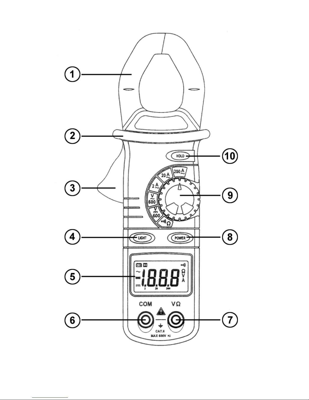
7. Front Panel Description (see figur e on next pag e)
① Jaws
They pick up the AC current flowing through the conductor.
② Probe Barriers
Keep your fingers behind the probe barriers during measurements.
③
Trigger
Press the lever to open the jaws. The jaws will close again when the lever is released.
④ Back light
Press the “LIGHT”-button to activate the back light for ± 5 seconds.
➄
Display
3 ½ digit LCD, max. reading 1999.
➅ “COM”-jack
This is the negative (-) input terminal for every type of measurement, with the exception of
current measurements. Connect the black test lead to this input terminal.
➆ “VΩ”-jack
This is the positive input terminal for voltage, resistance and continuity measurements.
Connect the red test lead to this input terminal.
➇ Power Button
Activates and deactivates the device.
➈ Range Selector
Used to select the correct range for the measurements.
➉ Hold-button
Press this button to freeze the last reading and make the “H”-symbol appear on the display.
Press this button again to make the “H”-symbol disappear and return to the normal mode.
DCM265 GB 3
Page 5
DCM265 GB 4
Page 6
8. Technical Specifications
****** General Specifications
Max. voltage between 600Vrms
the terminals
Installation Category II
Pollution Degree 2
Operating Temperature 0 to +40°C, RH < 80% non-condensing
Storage Temperature -10 to +60°C, RH < 70%
Operating Principle Dual-slope integration
Sampling Rate 2 readings/sec.
Display 3 ½ digit LCD display with max. reading of 1999. Automatic
function indication and symbol display
Range Selection Manual
Polarity Indication “-“ is automatically displayed to indicate negative polarity
Overrange Indication Only figure “1” is displayed
Jaw Opening 28mm (= max. size or Ø of the conductor)
Power Supply 3 x CR2032 battery (3V)
Battery-Low Indication The
-symbol is displayed
Dimensions 194mm (L) x 72mm (W) x 35mm (H)
Weight
±
200g (with batteries)
****** Measurement Specifications
Position the conductor within the jaws at the intersection of the indicated marks in order to
obtain max. accuracy. Positioning the conductor differently will result in an additional error of
1.5%.
Max. accuracy is achieved during a one-year period after calibration. Ideal circumstances
require an operating temperature of 18 to 28°C (64 to 82°F) and a max. relative humidity of
80%.
8.1. AC Current
Range Resolution Accuracy
2A 0.001A
20A 0.01A
± 1% of reading + 5 digits
200A 0.1A
Frequency Range : 50Hz to 60Hz
8.2. DC Voltage
Range Resolution Accuracy
600V 1V ±1% of rdg + 5 digits
Input Impedance : 10MΩ.
DCM265 GB 5
Page 7

8.3. AC Voltage
Range Resolution Accuracy
600V 1V ±1.5% of rdg + 5 digits
Input Impedance : 10MΩ
Max. Input Voltage : 600V dc or Vrms ac
Frequency Response : 40Hz – 400Hz
8.4. Resistance
Range Resolution Accuracy
2kΩ 1Ω ±1.0% of rdg + 5 digits
Open-Circuit Voltage : < 700mV
Overload Protection : 250V dc or 250Vrms ac
8.5. Audible Continuity
Range Continuity Beeper
≤
50Ω
Open-Circuit Voltage : < 700mV
Overload Protection : 250V dc or 250Vrms ac
9. Operating Instructions
Do not exceed the specified limit values in order to avoid overheating and damage. Do not
measure voltages > 600V to avoid risks of overheating and/or incorrect readings.
9.1. AC Current Measurements
1) Place the rotary switch in the desired A~ position.
2) Press the trigger to open the jaws. Put one conductor between the jaws and let them close
again, making sure that the conductor is gripped firmly.
3) The current value will appear on the display.
4) Select a higher range if the overrange indication ("1") appears on the display.
5) The meter may need a few seconds to produce a stable reading when measuring currents in
the 2A-range.
9.2. DC Voltage Measurements
1) Select the 600V
range with the range selector.
2) Connect the red test lead to the “VΩ”-jack and the black test lead to the “COM”-jack.
3) Connect the test leads to the circuit being tested and read the displayed value.
Note : the max. DC input voltage = 600Vdc. Measuring higher voltages may lead to damage or
electroshocks.
DCM265 GB 6
Page 8

9.3. AC Voltage Measurements
1) Place the rotary switch in the desired V~ position.
2) Connect the red test lead to the “VΩ”-jack and the black test lead to the “COM”-jack.
3) Connect the test leads to the circuit being tested and read the displayed value.
Note : the max. AC input voltage = 600Vrms ac. Measuring higher voltages may lead to damage
or electroshocks.
9.4. Resistance Measurements
1) Use the rotary switch to select the
Ω-range.
2) Connect the red test lead to the “VΩ”-jack and the black test lead to the “COM”-jack.
3) Connect the test leads to the resistor being tested and read the displayed value.
4) Disconnect the circuit to be tested and make sure that all capacitors have been fully
discharged before measuring the in-circuit resistance.
Remarks :
•
The overrange indication (“1”) will appear on the display if the input is not connected or if the
resistance being measured exceeds the max. value of the selected range.
•
Disconnect the circuit to be tested and make sure that all capacitors have been fully
discharged before measuring the in-circuit resistance.
• The meter may need a few seconds to produce a stable reading for resistance
measurements in excess of 1MΩ.
9.5. Continuity Test
1) Use the rotary switch to select the desired
Ω-range.
2) Connect the red test lead to the “VΩ”-jack and the black test lead to the “COM”-jack.
3) Connect the test leads to the resistor in the circuit being tested.
4) Connect the test leads to two points of the circuit to be tested. The built-in buzzer will sound if
continuity exists.
Remarks :
• Disconnect the circuit to be tested and make sure that all capacitors have been fully
discharged before measuring the in-circuit resistance.
• The continuity test enables the user to find open or shorted circuits.
10. Accessories
- user manual
- test leads
- carry case
DCM265 GB 7
 Loading...