


CTC710
Operation manual
Handleiding
Manuel
Wireless Voice Dialler
Draadloze doorkiezer
Transmetteur téléphone sans fil

Table of Contents
1. Introduction
1. What the Voice Dialler does
2. Model
2. Wireless Voice Dialler
1. Identifying the parts
2. About the power supply
3. How to mount the Voice Dialler
4. Preparing the Auto Dialler
5. Basic operation
6. How to connect the auxiliary detectors
7. Important notes

1. Introduction
1. What the Voice Dialler does
The Voice Dialler can store up to 6 telephone numbers and record and
play back emergency messages. With a total message capacity of 20
seconds, the choice is yours whether you store 1, 2 or 3 different
messages of variable length for different situations i.e. fire, burglar or
panic / emergency. During an emergency, the Voice Dialler will dial the
programmed telephone numbers in sequence until two calls have been
answered. It will play the appropriate recorded message to summon help
depending on the type of signal the Main Unit receives from its detectors.
The telephone numbers and the messages are all stored in EEPROM so
that no data is lost once programmed.
Types of alarm detected :
Fire from Smoke or Gas detectors
Burglar from Door Switch, PIR Detector or Broken
Glass Detectors.
Panic / Emergency from Panic or Silent Panic buttons or Hand
Held Controller or Emergency Pendant.
2. Model
The Wireless Voice Dialler is designed to be used with our wireless
home alarm systems. It can accept alarm signals from two sources :
1) Radio signal from the Main Unit.
2) Alarm signals from detectors attached to the unit itself.

2. Wireless Voice Dialler
1. Identifying the parts
1. RDY LED (green LED)
When idle, the LED will flash every 1 second. During setting in
keypad operation, the LED will speed flash. During dialling, the LED
will steadily on.
2. REC LED
The REC LED is on when the REC key is pressed to record message
and this LED will also come on when the recorded message is being
played.
3. NUMERIC KEYS
1. RDY LED
8. MICROPHONE
2. REC LED
4. SET KEY
5. TEST KEY
6. CE KEY
7. REC KEY

3. NUMERIC KEYS
These are used for keying in the emergency telephone numbers. You
can also set the priority of the telephone numbers to determine which
numbers are tried first in an emergency. When you wish to test the
system, you also use these key for specifying which number you want
to test.
4. SET KEY
The SET key is used to define the emergency telephone numbers and
relative priority numbers.
5. TEST KEY
The TEST key is used to test the Voice Dialler. It can actually dial
and get through to the emergency phone numbers you have selected.
6. CE KEY
The CE key will stop any current activity and return the Voice Dialler
to idle.
7. REC KEY
The REC key is used to record emergency messages.
8. MICROPHONE
9. PHONE JACK
10. SYSTEM ID CODE SWITCH BLOCK
The system ID code switch block contains 8 switches. There are 3
positions on each switch, up, middle and down position, being
marked "+", "o", "-" respectively allowing 6561 code combinations.
These switches are used to set the system ID code.
11. DC 12V JACK
For connecting the AC adapter.
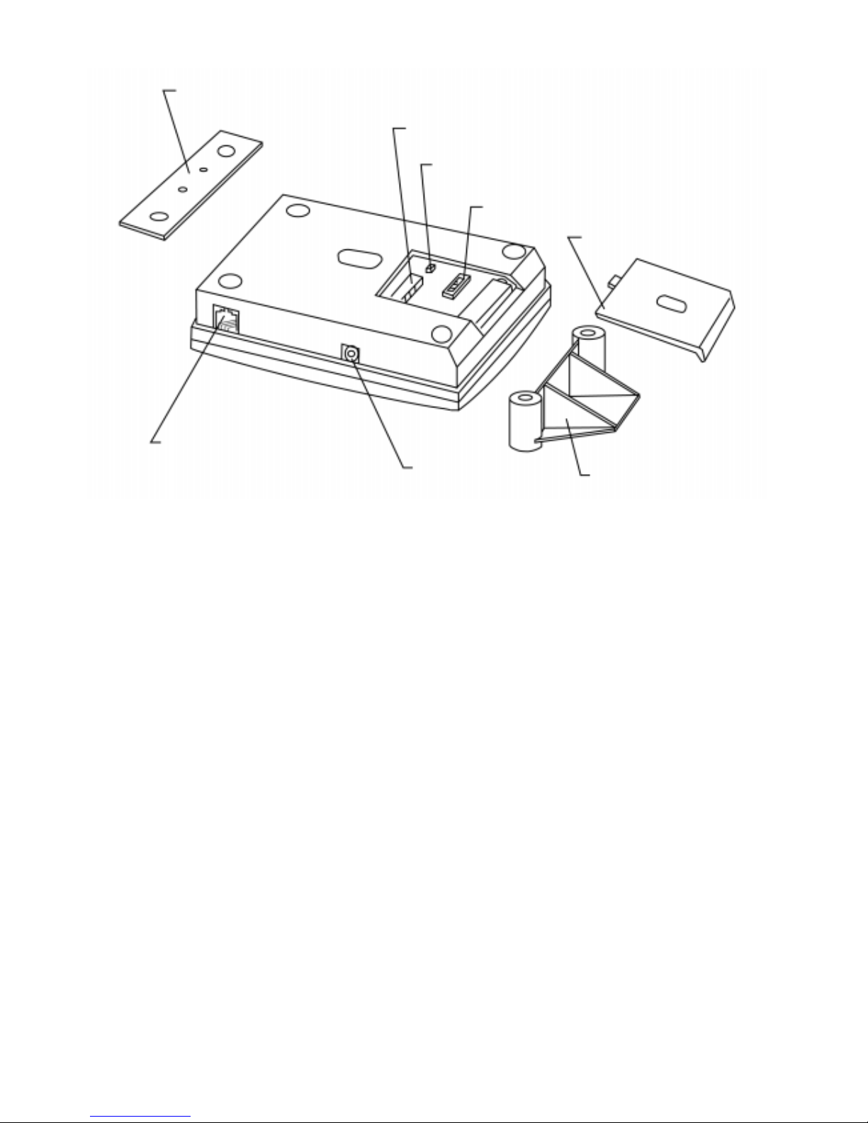
12. TONE/PULSE SELECTION JUMPER
This 2-pin jumper (JP2) is used to select whether traditional pulse
dialling or tone dialling method is used. If tone dialling is used, the 2
pins of the jumper or shorted (with a clip between them). If
traditional pulse dialling is used, the 2 pins of the jumper are opened
(without a clip between them). Tone dialling is the default setting.
13. TERMINAL BLOCK
This 5-pin terminal block is for connecting any existing non-wireless
alarm detectors you may have. When the detector connected to the
Voice Dialler is activated, the Voice Dialler will directly dial and
send the message. However, the Main Unit will not be activated.
14. PROTECTIVE COVER
15. TABLE MOUNT BRACKET
16. WALL MOUNT BRACKET
16. WALL MOUNT BRACKET
9. PHONE JACK
11. DC 12V JACK
15. TABLE MOUNT
BRACKET
14. PROTECTIVE COVER
10. SYSTEM ID CODE SWITCH BLOCK
12. TONE/PULSE SELECTION JUMPER
13. TERMINAL BLOCK

17. PLUG-SOCKET CABLE
2. About the power supply
An AC power adapter is required to connect to a wall outlet. Use only an
adapter with the appropriate AC voltage ratings to prevent component
damage. The adapter should provide 12V DC output and 300mA
capacity.
The Voice Dialler has 2 options, with built-in rechargeable battery or
without battery.
With rechargeable battery
In addition to the adapter, there is a rechargeable battery inside the Voice
Dialler which serves as a back-up in case of power failure. The battery
used is Ni-Cd 8.4V rechargeable battery.
During normal operation, the AC power adapter is used to supply power
to the Voice Dialler and at the same time recharge the battery. When the
battery is fully charged, it can provide back-up power for a period of at
least 7.5 hours. It takes approximately 36 hours to charge the battery
fully.
Plug-Socket cable
The Tel line provided by
the tel company is plugged
into this phone jack.
The tel set is plugged
into this phone jack.
Plug into the phone jack
of the Voice Dialler.

3. How to mount the Voice Dialler
The Voice Dialler can be placed on top of a table or mounted on the wall.
For table mounting, position the bracket as the picture shown below, then
slowly lift the bracket upwards.
4. Preparing the Voice Dialler
1) Open the protective cover.
2) Set the system ID code.
To set the ID code, slide open the protective cover, you will see 8-dip
switches are set as following :
Switch 1, 5, 8 are in the up position.
Switch 2, 4, 6 are in the middle position.
Switch 3, 7 are in the down position.
This is the default setting.
If you wish to change the setting, use a small screw driver to set the
new system ID code. The same ID code should appear on each unit in
the system.

Note : If you are using this Voice Dialler with our alarm system
having 256 ID code combinations, (that is when the system
ID code switch block of the alarm system has only 2
positions, up being the ON position and down being the OFF
position), please not the down position marked as "-" of the
Voice Dialler can’t be used. Only the up and middle position
can be used.
Voice Dialler (6561 codes) Alarm System (256 codes)
UP (+) = UP (ON)
MIDDLE (o) = DOWN (OFF)
DOWN (-) not used
3) Set the tone/pulse jumper
If your telephone system uses tone dialling, make sure the tone/pulse
jumper is shorted (with a clip between them). If your telephone
system uses traditional pulse dialling, pull up the clip (jumper should
be opened).
4) Close the protective cover.
5) Hang the Voice Dialler on the wall or put the Voice Dialler on top of
the table by using the appropriate bracket.
6) Plug the cord of the AC adapter into the DC jack.
7) Plug the AC adapter into the wall outlet. You will hear a beep sound
and the RDY LED (green LED) will start flashing. The Voice Dialler
is now ready for operation.
5. Basic operation
Notes :
A. When pressing any key, you will hear a beep, this lets you know
the keystroke has been accepted.
B. When entering keystrokes, the interval between two keystrokes in
a setting sequence must not exceed 5 seconds, otherwise, the keys
you have entered earlier will be ignored and the Voice Dialler
will return to idle.

C. When idle, the RDY LED is flashing slowly every 1 second.
When you start the setting, the RDY LED will flash fast. This let
you know the setting is in progress.
D. If any time you want to abort the current keyings, just press "CE"
and you can restore again.
E. If a setting sequence is sucessfully done, you will hear a long
beeping indicating the setting is accepted. However, if bi-bi-bi
sound is heard, this indicates the setting is incomplete or aborted,
or the interval between two keystrokes exceeds 5 seconds.
1. Store telephone numbers
The Voice Dialler can store as many as 6 telephone numbers, you can
also set the priority of the phone numbers toe determine which
numbers are tried first in an emergency.
a. Store a normal telephone number
To store the telephone numbers, press SET, key in the priority
number to be given to the telephone numbers, then key in the
phone number up to 20 digits, then press SET.
Press SET
Key in priority number (1-6)
Key in phone number up to 20 digits
Press SET
b. Store a pager number
Press SET
Key in priority number (1-6)
Key in pager number up to 15 digits
^^ Press #
Key in 3 digits identity code
^^ Press #
Press SET

The identity code is a 3-digit number you can key in any number
at your discretion. This enables the recipient to know the call is
from the Voice Dialler.
^^Note : The procedure to store pager number may vary depending
on the pager system used in a specified area. The
#
represents a delay period of 5 seconds and Voice Dialler
will dial #. If the delay period of the pager system in your
area is more than 5 seconds, you can extend the delay
period by adding "*" before the #. You can add as many
"*" depending on the delay period required. Each "*"
represents a delay period of 3 seconds, but the Voice
Dialler will not dial "*". The users may change the
procedure in ^^ depending on the pager system used in
their area.
c. Store a telephone number with extension number.
Press SET
Key in priority number (1-6)
Key in telephone number
Press *
Key in extension number
Press SET
Note : 1. The telephone number + * key + extension number
should not exceed 20 digits.
2. The * key when pressed here represents a delay period
of 3 seconds. This means the Voice Dialler will wait for
3 seconds and will continue dialling after the delay
period is over. If you want to extend the delay period,
you can add more "*". Each "*" represents a period of 3
seconds.

d. Store the telephone number in an EPABX telephone system.
If you Voice Dialler is installed in an EPABX system, the
EPABX access code "0" or "9" and * key must be keyed in after
the priority number.
Press SET
Key in priority number (1-6)
Press 0 or 9 (EPABX access code)
Press *
Key in phone number up to 18 digits
Press SET
2) Cancel the telephone number
a. When two same priority number has key in, the last telephone
number will overwrite the previous number. For example, you
have first key in priority number 1 and telephone number 223344,
then afterwards you have key in priority number 1 and telephone
number 445566. The telephone number 445566 will be recorded
as priority number 1.
b. If any of the priority number is to be cancelled :
Press SET
Key in priority number (1-6)
Press SET
3) Record the emergency message
With a total message capacity of 20 seconds, the choice is your
whether you store 1, 2 or 3 separate messages of variable length for
different situations (fire, burglar & panic/emergency).
If you record 3 messages, record the fire alarm message as message
no. 1, the burglar alarm message as no. 2 and the panic/emergency
alarm message as message no. 3. This is necessary so that the system
can send out the appropriate message depending on the type of alarm.

If you record 2 messages, record the fire alarm and panic/emergency
alarm message as message no. 1, the burglar alarm message as
message no. 2.
The procedure to record the message is : press REC, press 1 / 2 / 3 (as
message no. 1, no. 2, no. 3), press REC (you will hear a long beeping
sound and the REC LED will come on then you can start recording),
then press CE (to stop the recording).
Press REC
Press 1 / 2 / 3 (depends on message no. 1, no. 2, no. 3)
Press REC
Press CE
Note : 1. After you press REC, 1 (or 2 or 3) and REC, if you hear 3
beep sound and the REC LED does not light. It means there
are some messages already stored and cannot record again.
You have to clear the memory first.
2. The recording capacity is 20 seconds, when the total
message recorded is over 20 seconds, the REC LED will
come off and recording is stopped.
3. When recording, make sure you are facing the microphone
and the distance should not be more than 30cm.
4) Change the recorded message
If you want to change any portion of the message recorded, you first
have to erase/cancel all the recorded messages, then afterwards
record the new messages all over again.
5) Cancel the recorded message
If you wish to cancel the recorded message, press REC, 0, and REC.
All the messages will be erased in the same time.
Press REC
Press 0
Press REC

6) Stop the dialling
If any time you want to stop the dialling, just press CE.
7) Dialling test
To check if the Voice Dialler can actually dial the number you have
set and send the pre-recorded message, press TEST then key in the
priority number (1-6) of the telephone number you wish to test.
When dialling is successful, the Voice Dialler automatically
broadcasts the message(s) three times following the sequence of
message 1-2-3-1-2-3-1-2-3, if there are 3 messages recorded.
When the number dialled is engaged, the Voice Dialler will redial the
number for a maximum of 5 times with an interval of 62 seconds.
To stop the testing, just press CE.
6. How to connect the auxiliary detectors
1) The 5-pin terminal block is for connecting any existing non-wireless
detectors. They are labelled 1 to 5 from left to right on the PCB.
}}}
}
12V DC
FIRE ALARM DETECTOR INPUT
BURGLAR ALARM DETECTOR INPUT
EMERGENCY INPUT

If you have any smoke or gas detectors, connect them across pin 1
and pin 4.
If you have any PIR, door switch or broken glass detectors, connect
them across pin 2 and pin 4.
If you have any panic/emergency button, connect them across pin 3
and pin 4.
Pin 4 and pin 5 provide 12V DC output for the detector. Pin 4 is 12V
DC "-" (negative) polarity. Pin 5 is 12VDC "+" (positive) polarity.
2) The detector used should be a "normally closed" (N.C.) device. Any
of the 3 pins (pin 1, 2, 3) and pin 4 of the terminal form a closed loop
with the detector. If the circuit between any of the 3 pins and pin 4 is
opened, the alarm will be activated.
3) When the detector connector to the Voice Dialler is activated, the
Voice Dialler will directly dial and play the message recorded.
However, the Main Unit will not be activated.
7. Important notes
1) When only one number is stored and the number is engaged, the
Voice Dialler will automatically redial that number up to maximum
of 5 times with an interval of 62 seconds.
2) When more than one telephone numbers are stored, the Voice Dialler
will dial in accordance to the priority number. If the number being
dialled is engaged, it will try the next number and so on.
Each number will be tried a maximum of 5 times and the redial
interval between each number is 35 seconds.
3) When the Voice Dialler has reached 2 successful phone calls, it will
stop dialling.
4) When the recipient has answered the call, the Voice Dialler will start
to play the message after 2 to 5 seconds thereafter. It will repeat the
message for 3 times.

5) If no message or no telephone number is stored, the Voice Dialler
will not dial.
6) If certain type of alarm occurred, but the corresponding message is
not stored, the Voice Dialler will play message no. 1.
 Loading...