

Page 1
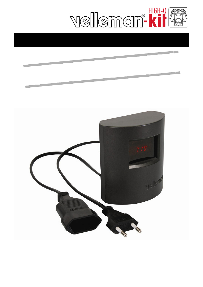
LED CLOCK with SLOW ON DIMMER
on
i
t
c
e
n
n
o
c
t
h
g
i
l
t
h
g
i
n
h
t
i
w
k
c
o
l
c
D
E
L
e
v
i
t
c
a
r
t
t
A
Total solder points: 120
Difficulty level: beginner 1 2 3 4 ⌧ 5 advanced
K8091EU
K8091EU
ILLUSTRATED ASSEMBLY MANUAL H8091IP-1
Page 2

Page 3

Features & specifications
The K8091 is an attractive LED clock with connection possibility for a nightlight.
15 minutes before the set time, the light intensity of the connected light will
increase up to full power at set time and beeps will be heard. The beep length is
gradually built up so you will not be startled by a sudden alarm signal.
Features :
clock with red 7-segment display.
possibility to connect any lamp armature fitted with an incandescent light bulb
sleep function (15 min) for slow light power-off.
snooze function with alarm repeat function after 8 min.
manually settable light intensity.
beep and / or light option.
Specifications
• power supply: 220- 240V AC / 50Hz.
• lamp power: 40 ~ 100W max.
• power consumption: < 1W (without lamp)
• dimensions: 92x45x101mm / 3.6x1.8x3.9"
WARNING !
ALL PARTS IN THIS KIT CARRY HAZARDOUS VOLTAGES WHICH CAN KILL !
Do not touch any part of the kit while connected to the AC grid.
Do not modify the kit in any way.
Do not use the kit if the enclosure is damaged or open.
For use with regular incandescent lightbulbs (40-100W) only.
Not suited for low-voltage halogen lighting, energy saving bulbs, led lighting,
fluorescent lighting, motors, buzzers, transformers etc...
We highly recommend to have your kit inspected by a qualified technician
before connecting it to the AC power for the first time or after a malfunction.
3
Page 4
Assembly hints
0
.
0
0
0
1. Assembly (Skipping this can lead to troubles ! )
Ok, so we have your attention. These hints will help you to make this project
successful. Read them carefully.
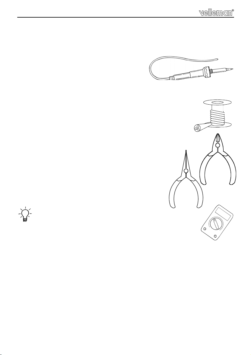
1.1 Make sure you have the right tools:
• A good quality soldering iron (25-40W) with a
small tip.
• Wipe it often on a wet sponge or cloth, to keep it clean; then apply solder to
the tip, to give it a wet look. This is called ‘thinning’ and will protect
the tip, and enables you to make good connections. When solder
rolls off the tip, it needs cleaning.
• Thin raisin-core solder. Do not use any flux or grease.
• A diagonal cutter to trim excess wires. To avoid injury when cutting
excess leads, hold the lead so they cannot fly towards the eyes.
• Needle nose pliers, for bending leads, or to hold components in place.
• Small blade and Phillips screwdrivers. A basic range
is fine.
For some projects, a basic multi-meter is required, or might
be handy
1.2 Assembly Hints :
⇒ Make sure the skill level matches your experience, to avoid disappointments.
⇒ Follow the instructions carefully. Read and understand the entire step before
you perform each operation.
⇒ Perform the assembly in the correct order as stated in this manual
⇒ Position all parts on the PCB (Printed Circuit Board) as shown on the draw-
ings.
⇒ Values on the circuit diagram are subject to changes.
⇒ Values in this assembly guide are correct*
4
Page 5
Assembly hints
⇒ Use the check-boxes to mark your progress.
⇒ Please read the included information on safety and customer service
* Typographical inaccuracies excluded. Always look for possible last minute
manual updates, indicated as ‘NOTE’ on a separate leaflet.
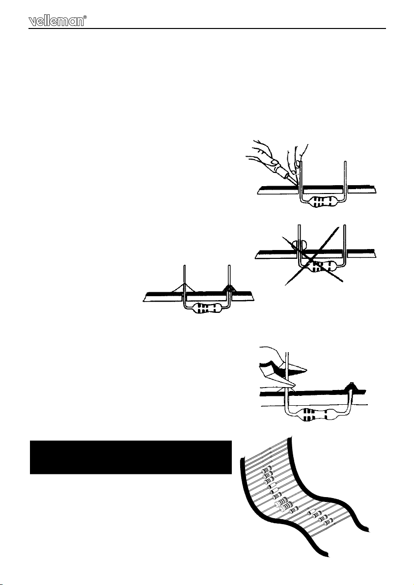
1.3 Soldering Hints :
1- Mount the component against the PCB
surface and carefully solder the leads
2- Make sure the solder joints are cone-shaped
and shiny
3- Trim excess leads as close as possible to the
solder joint
AXIAL COMPONENTS ARE TAPED IN
THE CORRECT MOUNTING SEQUENCE !
REMOVE THEM FROM THE TAPE ONE AT
A TIME
!
5
Page 6

Construction
CATHODE
ZD...
c...
(1) ASSEMBLY OF THE COMPONENT SIDE
1. Resistors
R...
1/8W:
R1 : 100 (1 - 0 - 1 - B)
R2 : 100 (1 - 0 - 1 - B)
R3 : 100 (1 - 0 - 1 - B)
R4 : 100 (1 - 0 - 1 - B)
R5 : 100 (1 - 0 - 1 - B)
R6 : 100 (1 - 0 - 1 - B)
R7 : 100 (1 - 0 - 1 - B)
R13 : 10K (1 - 0 - 3 - B)
R14 : 10K (1 - 0 - 3 - B)
R16 : 10 (1 - 0 - 0 - B)
1/2W "metal film" :
R8 : 47 (4 - 7 - 0 - B - 9)
R9 : 10 (1 - 0 - 0 - B - 9)
R10 : 470K (4 - 7 - 4 - B - 9)
R11 : 470K (4 - 7 - 4 - B - 9)
R12 : 100K (1 - 0 - 4 - B - 9)
1/4W:
R15 : 220 (2 - 2 - 1 - B)
3. Zener diode (check the polarity)
ZD1 : 15V0
4. IC socket. Watch the position of
the notch!
IC1 : 18p
1
IC...
Mind the position of the notch and shorten
the connection pins as short as possible
after soldering!
5. Capacitors
C1 : 100nF (104)
C2 : 100nF (104)
C3 : 100nF (104)
C4 : 10nF (103)
C5 : 100pF (101)
6. Fuse.
F1 : 1A
2. Diodes (check the polarity)
CATHODE
D...
D1 : 1N4148
D2 : 1N4148
D3 : 1N4148
D4 : 1N4148
D5 : 1N4007
6
7. Buzzer
BUZ1
(3-6VDC/25mA)
BUZ...
+
Page 7

Construction
C...
TR...
8. Transistor
T1 : BC547
9. Voltage regulator
T1
VR2 : UA78L05
VR...
10. 1W Resistor
R17 : 220 (2 - 2 - 1 - B)
13. Capacitors
14. Push buttons
SW1
SW2
SW3
15. Triac
TR1 : BT136
C6 : 100nF
C7 : 470nF
11. Electrolytic capacitors.
Watch the polarity !
C8 : 220µF
C9 : 10µF
12. Terminal blocks
SK1 : 2p (AC IN)
SK2 : 2p (output)
16. IC
IC1: VK8091EU
Programmed PIC16F627A
7
Page 8

Construction
(2) MOUNT THESE COMPONENTS ON THE PCB SOLDERSIDE, SOLDER
THEM ON THE COMPONENTS SIDE
1. Four digit display & coil
• Mount the four digit display first.
DY1 : 4-digit
min.
2mm
• Mounting the coil:
1) Cut the rubber foot and stick it to the PCB as shown.
2) Position the coil onto the rubber foot. Bend the leads carefully and insert
them into their soldering pads. Solder carefully.
!
8
Page 9

construction
2. Power cable
• Cut 45cm of the included cable, measured from the female connector.
+/- 45cm
• Put both cables trough the hole on the rear cover of the housing.
• Strip the male and female cable.
• Connect the female cable/connector to the output connector
SK2, the male cable/connector to output connector SK1
• When both cables have been connected to the K8091EU
mount the strain relief and tighten up with the included 15mm
bolts and M3 nuts.
20mm
Twist & thin the wires!
SK1 SK2
L N N L
AC OUT
M3 bolt
7mm
Strain relief
SK2
SK1
M3 lock washer
M3 nut
9
Page 10

Assembly
3. Assembly
• Before mounting the PCB on its place you must mount
the red display.
• After placing the red display mount the
PCB in the front cover with the 4-digit
display facing to the red
display window with 4 screws.
• At last mount the rear of the housing
and closed with 4 screws.
Rear-sticker
Stick the rear sticker on the backside of the housing, see figure.
Product description
Indications :
(a)
(b)
(c)
Control :
10
time set
alarm set
light/buzzer
select mode
Light / Buzzer
sleep / snooze
dim / cancel alarm
time
hour
minutes
alarm/light
activated
run mode
on
off
Page 11

4. Connection
Connection
lamp power: 40 ~ 100W
power supply: 220- 240V AC / 50Hz.
5. First power-up
At first power-up
Make sure to read and understand the important safety information on p. 3
At first power-up the product number 8091 and version software appear.
Default setting
The default setting is the blinking clock time 0:00 with a default alarm time 07:00
and alarm functions (light+buzzer) deactivated.
Note: From the moment that the alarm time is changed will this time be the
default setting alarm time.
6. Setting time / alarm / alarm functions
Time-setting:
• First press the "select" button to enter the time set mode, the 'time set' indicator will blink.
• Press the middle button to set the minutes, the right button for the hours.
• Confirm the setting by pressing the select-button, once confirmed you will
automatic enter the alarm-mode.
11
Page 12

Setup
Alarm:
Note: If you are not entering this mode after the time setting you must press twice
the 'select' button to enter the alarm mode. The 'alarm set' indicator blinks to
confirm you're in the alarm mode.
• Press the middle button to set the minutes, the right button for the hours.
• Confirm the setting by pressing the select-button, once confirmed you will
automatic enter the alarm function mode.
Alarm functions:
Note: If you are not entering this mode after the alarm setting you must press
three times the 'select' button to enter the alarm mode.
The 'alarm set' indicator blinks to confirm when you're in the alarm mode.
You can choose between 3 possibilities for wake-up alarm
1. Light
2. Buzzer
3. Light & Buzzer
(LI.on or LI.oF)
(bU.on or bU.oF)
:
Note: Press the "select" button to go trough the setup mode and to exit.
SETUP SEQUENCE:
Hour mode Alarm mode
Display
Light mode Buzzer mode
Setup mode
12
Make sure that the switch of your nightlight is activated!
Page 13

7. Alarm process
light control
SEQUENCE:
* min. 15 minutes
alar m ti me time
*
Light at maximum
Buzzer on
Snooze
Off
8 minutes
Alarm is switched off
Buzzer on
Snooze
Off
. . .
The repeat function of the buzzer will automatically repeat every 8minutes until
the alarm is deactivated by pressing the manual on/off button.
Note: if the light was already illuminated more than 15minutes before the alarm
time, will the alarm-light increase from that point to its maximum.
8. Manual light control
The nightlight can be switched on trough the alarm or manually.
When you want to do it manually you can let it light up or down in gradation or
directly to 100% or directly extinguish the light.
Letting the light growing up or down in gradation by holding the middle button
pressed until the desired level is reached.
With a short press you go directly to the maximum or minimum light intensity.
light at maximum
max.
0
light intensity
short press
light at minimuum
0
max.
long press
light intensity
light at maximum
Note: whit a short press after a dimming function the
light will go directly to it's maximum or minimum, the
direction will be equal to the last dimming direction.
13
Page 14

PCB
9. PCB
14
Page 15

10. Schematic diagram
Schematic diagram
15
Page 16

VELLEMAN KIT NV
Legen Heirweg 33
9890 Gavere
Belgium Europe
Info ?: http://www.velleman.be
Modifications and typographical errors reserved
© Velleman Kit nv
H8091IP - 2009
5 410329 409234
 Loading...